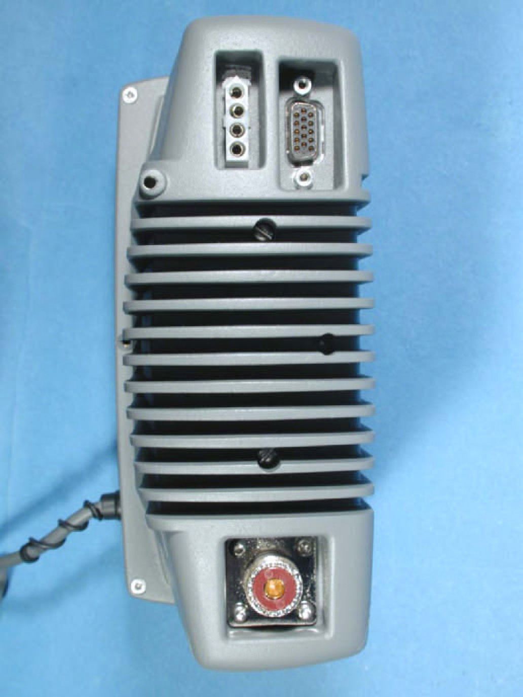
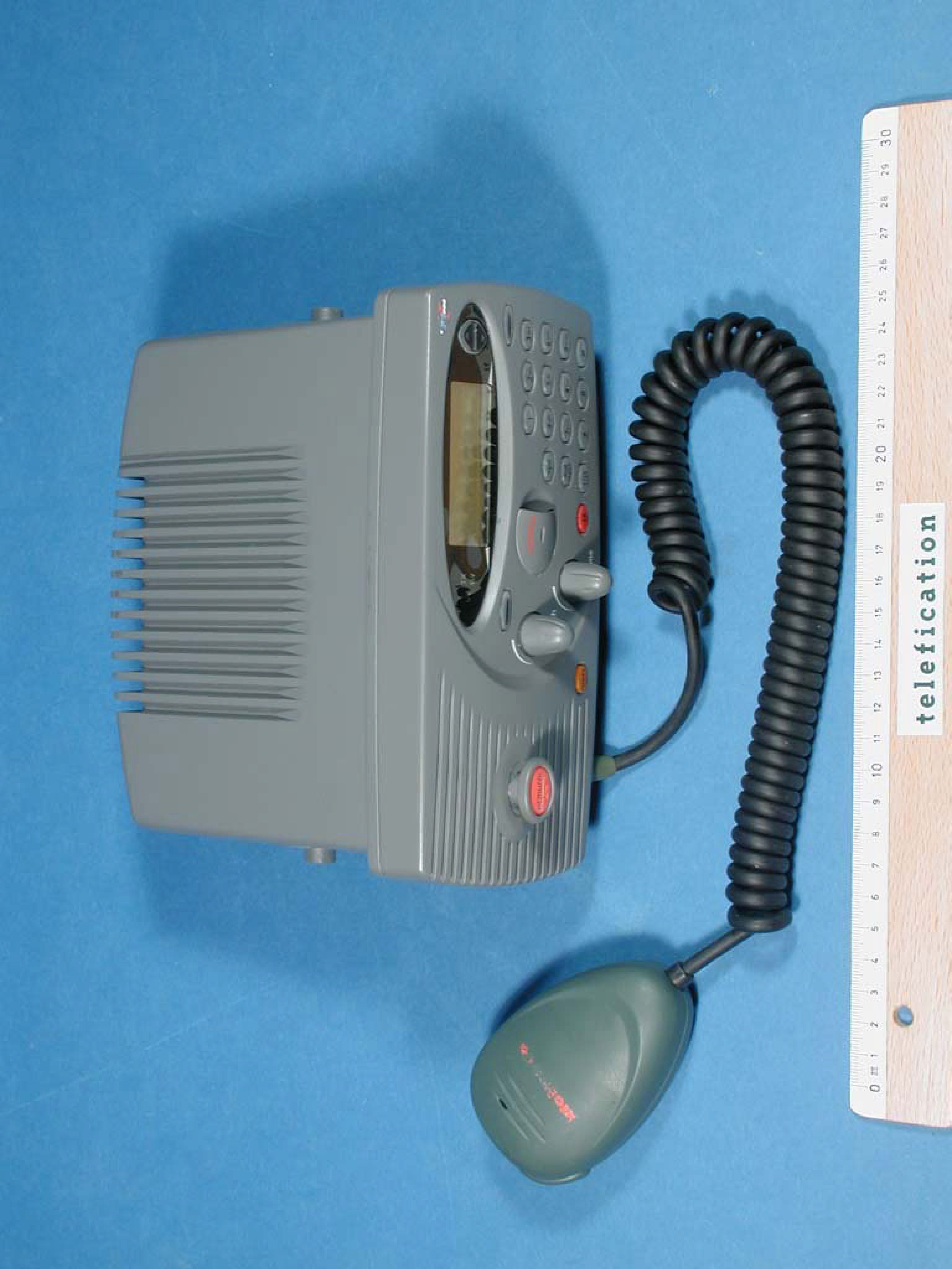
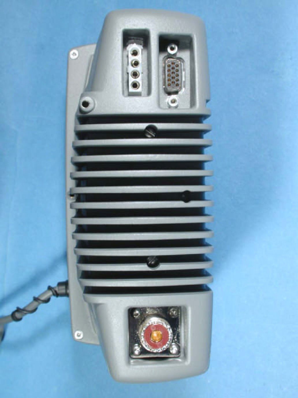
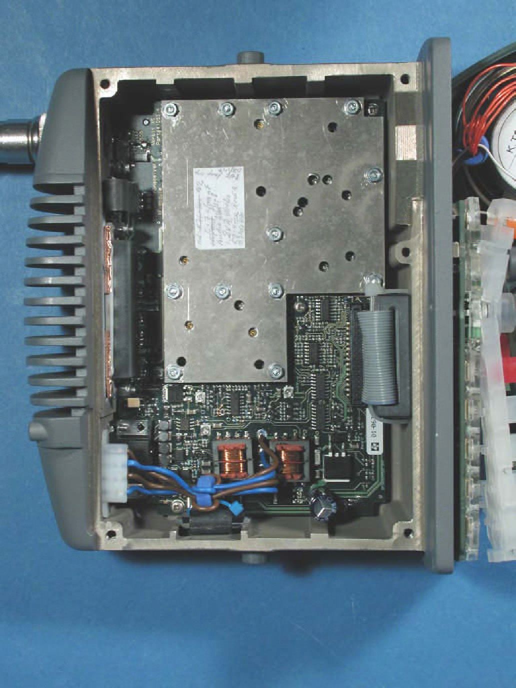
KLSF1DSCVHF Marine radiotelephone inc.class 'D' DSC
Orolia Ltd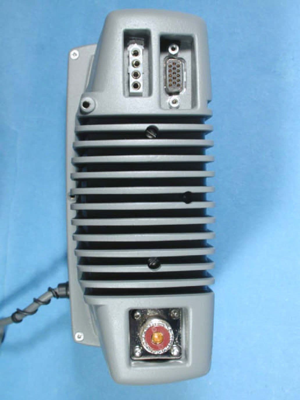
Click to zoom
Application Details
- Equipment Class
- TNB - Licensed Non-Broadcast Station Transmitter
- Date of Grant
- Feb 05, 2003
- Application Purpose
- Original Equipment
- Date of Application
- Dec 09, 2002
- Equipment Note
- VHF Marine radiotelephone inc.class 'D' DSC
- Frequency Range
- 156.00000000 - 163.00000000
- Company
- Orolia Ltd
- Country
- United Kingdom
Documents & Files
Document Text
Text extracted from the exhibit documents filed with the FCC. Open a document above to read the original.
Users Manual
McMurdo F1 DSC Marine VHF Radio with DSC Installation Manual ii Introduction McMurdo McMurdo has supplied the maritime market for many years with communication products of high quality and excellent design, and considers it of utmost importance that all products are safe and easy to operate. The product The McMurdo F1 DSC VHF Radiotelephone (radio transceiver) is designed to meet the high quality standard required for a product that plays an important role in the safety of the ship and its crew. The F1 DSC Radiotelephone is easy to operate and gives the user high quality effective radio communication to other ships as well as to shore based stations. Installation and maintenance is made very simple and can be carried out by untrained personnel. Training certificate The F1 DSC Radiotelephone is very simple to use; the menu-structured operation is user-friendly, self-explanatory and simple to navigate. However the use of VHF marine radios including DSC is legislated; it is therefore necessary for the user to have a certificate from the legislating authority in the country where the radio is to be used. When the radio is registered the legislating authority will issue the MMSI number necessary for the operation of the DSC function. A CD-ROM simulating the operation of the F1 DSC Radiotelephone can be obtained from McMurdo on application. This, when installed on a PC-compatible computer, simulates the operation of the F1 DSC Radiotelephone together with a simulation of a second station for exchange of DSC messages. Service McMurdo has established a worldwide service network ready to support any requirement concerning the F1 DSC Radiotelephone. The service network ensures that spare parts and installation advice can be obtained in all major ports of the world. The Certified Services Centre concept ensures that the performance of the Service Centres is constantly monitored and that the skills of the personnel are up to date. Details of the McMurdo worldwide service network can be found on the website: www.mcmurdo.co.uk iii Maintenance The F1 DSC Radiotelephone is an essential part of the ship’s emergency system. As the radio is a vital component for the safety of the ship and its crew it is very important to maintain the radio and its installation to a very high standard. The design of the radio ensures that maintenance can be kept to a minimum, however it is good practice to perform a functional check at least once every month. This functional check is described in this manual and takes only a few minutes to carry out. It is essential to perform a functional check following installation. It is also important to inspect all cables and connections at regular intervals, such as twice yearly. Disclaimer Information contained in this manual is supplied in good faith, but is liable to change without notice. McMurdo Limited disclaims any liability for consequences arising from omissions or inaccuracies in the manuals and documentation provided with this product. 2002 McMurdo Ltd. IMPORTANT: Please take time to read this manual carefully and to understand its contents fully, so that you can install your F1 DSC Radiotelephone correctly. If in any doubt seek expert advice or have a skilled person install it for you. Once installed please read the Operation Manual fully to make sure you understand how to use your new radio. iv Installing and Using the Transceiver Safely Installation WARNING: Do not connect the transceiver to a mains (line) AC electrical supply, as an electric shock or fire hazard could result. CAUTION: Do not connect the transceiver to a DC supply exceeding 16V or reverse the supply polarity. Damage to the transceiver can result. CAUTION: Do not bypass the power cable inline fuse (such as cutting the cable shorter). CAUTION: The transceiver is designed for operation in the temperature range –15°C to +55°C. Do not install (or use) the transceiver in areas which exceed this range. CAUTION: The F1 DSC radio is water resistant to international standards. However, if either the transceiver or microphone casing is damaged (e.g. due to heavy impact) then the sealing cannot be guaranteed. WARNING: Do not install the receiver in a position where; a) the controls of your vessel may be obstructed. b) it may obstruct your normal movement around your vessel. c) it may cause bodily injury. d) it cannot be easily accessed in an emergency. Use WARNING: Certain parts of the chassis can become hot during extended periods of operation, notably the rear panel (connectors and radiator fins). Avoid touching these areas when the radio is operating. WARNING: Do not touch the rear connections, notably the antenna connector, when the transceiver is operating and do not touch the antenna whip (mast) or connecting cable when operating the transceiver, for RF exposure and electrical safety reasons. Refer to Radio Frequency Exposure Warning. WARNING: Opening the transceiver cover will invalidate the warranty. Do not open the cover when the transceiver is operating, or connected to a power supply. Maintenance CAUTION: Avoid using chemical solvents to clean the transceiver as some solvents can damage the case material. NOTE: The transceiver contains no user serviceable parts. Return to your Service Agent for repair. v Radio Frequency Exposure Warning To meet the current requirements for Radio Frequency Exposure it is necessary to install the antenna mast correctly and operate the equipment according to the instructions. The assumptions used in this assessment are: full transmit power is used, a good antenna is used (assumed to be a 9dBi gain omnidirectional type). Where no suitable structure exists to achieve a 3 metre vertical separation then the antenna base must be mounted at least 1 metre above the head of any person within range and all persons must stay outside the 3 metre safety radius. Failure to adhere to these limits could expose persons within the 3 metre radius to RF radiation in excess of the MPE / SAR …
Text truncated - open the document above for the full version.
Users Manual
McMurdo F1 DSC Marine VHF Radio with DSC Operation Manual Controls Disclaimer Information contained in this manual is supplied in good faith, but is liable to change without notice. McMurdo Limited disclaims any liability for consequences arising from omissions or inaccuracies in the manuals and documentation provided with this product. 2002 McMurdo Ltd. IMPORTANT: Before you use this transceiver, read and understand all the instructions in this manual. Power switch Distress cover PTT switch Left action key Right action key IndicatorsScroll keys Rapid Distress Call 1. Turn the radio ON (press POWER) 2. Open the cover over the DISTRESS button and press the button. If the button is pressed for 5 seconds an ‘undesignated’ distress call will be made. If the button is released before 5 seconds, you can select the type of emergency. If the position information is too old to be valid, you will be prompted to update it. (See Page 6 for full details.) 3. If there is insufficient time to enter position information keep pressing the Distress Button. Do not release the button until you see this screen. 4. Wait approximately 15 seconds for an acknowledgement. 5. When the acknowledgement is received, the radio switches automatically to Channel 16. Pick up the microphone, press the PTT (TALK) button and call for help: ‘MAYDAY, MAYDAY, MAYDAY This is Ship name, Ship name, Ship name MAYDAY This is Ship name, Callsign. Position:..................................... Nature of distress:........................ Help needed:............................... (any other information) OVER’ Distress Call Undesignated Wait for Acknowledge Reset 16 IMPORTANT: Do NOT make a distress call unless there is grave and imminent danger. It is an offence to make any unjustified distress call. Introduction Thank you for choosing McMurdo for your VHF communication requirements. McMurdo has supplied the maritime market for many years with communication products of high quality and excellent design, and considers it of utmost importance that all products are safe and easy to operate. The product The McMurdo F1 DSC VHF radiotelephone is designed to meet the high quality standard required for a product that plays an important role in the safety of the ship and its crew. The F1 DSC VHF radiotelephone is easy to operate and gives the user high quality effective radio communication to other ships as well as to shore based stations. Installation and maintenance is made very simple and can be carried out by untrained personnel. A CD-ROM simulating the operation of the F1 DSC radiotelephone can be obtained from McMurdo on application. This, when installed on a PC-compatible computer, simulates the operation of the F1 radio together with a simulation of a second station for exchange of DSC messages. VHF DSC Radios VHF radios communicate on fixed frequency bands called channels. There are 57 public channels, numbered 1 to 28 and 60 to 88. (The system is different in US waters; setting the radio to US changes to that system.) Some channels are reserved for particular functions: Channel 16 is reserved for verbal distress calls and for ‘All Stations’ calls. This channel must NOT be used for other purposes. Channel 70 is a channel reserved for digital data (DSC). DSC (Digital Selective Calling) is a digital function which permits a caller to alert a particular DSC radio (or group of radios) that a standard radio communication is requested on a specific channel. In this respect, it is similar to a standard telephone call in that a specific number can be called; however, once the call is accepted, communication uses normal radio procedures. DSC also permits automatic distress call alerting; where the appropriate information is available from external equipment, the alert includes the vessel’s MMSI number, its position and the exact time of the distress alert. (The distress call is still made using conventional radio procedures; the DSC function only alerts other radio users to the intended call.) Verbal Communication Verbal communication is of two types: simplex and duplex. • Simplex communication uses a single frequency, so only one transmitter can be operating at any time. This means that each party in the conversation must say ‘over’ when stopping transmitting so that the other party knows it is their turn to transmit. All ship-to-ship communication is in simplex mode. The F1 DSC radiotelephone supports simplex communication. • Duplex communication uses two frequencies, so both parties can talk at the same time. The F1 DSC radiotelephone does not support full duplex operation. • There is also a hybrid mode: semi-duplex. In this mode, one of the communicating parties operates in duplex mode and the other in simplex. A good example is ship to coast station communications. The F1 DSC radiotelephone supports semi-duplex communication. DSC Digital Communication DSC (Digital Selective Calling) is a system for establishing communication to a specified address, to a ‘group’ (a pre-defined set of addresses), or to ‘all parties’ for a digital distress call. The key feature of the DSC system is the use of the vessel’s MMSI (Maritime Mobile Station Identity) number to identify each vessel. (This number is treated as the vessel’s DSC telephone number.) Consequently, before a DSC call can be made, the originating vessel’s MMSI must be programmed into its radio and the receiving vessel’s MMSI must be known to the caller. All DSC communication is on Channel 70. The radio maintains a continuous watch on this channel for incoming messages, which are immediately reported. This monitoring also allows the system to transmit only when the channel is free. The radio responds to three types of DSC message: All ships calls. These calls are received by all vessels within range of the transmitter. Individual calls. These calls are addressed specifically to the radio MMSI number. Group calls. When the radio has been set up as a member of a group, it responds to calls …
Text truncated - open the document above for the full version.
Block Diagram
MATERIAL :- DIMENSIONS IN :- TITLE. FINISH :- 3RD ANGLE PROJECTION B.S.8888 McMURDO LIMITED. PORTSMOUTH-HAMPSHIRE-ENGLAND DRAWING No. DRAWN.APPROVED. RELEASED.SCALE. APPD.DATE.CHG.No.ISSUE.APPD.DATE.CHG.No.ISSUE. ORH11/07/02C22321 USED ON AUDIO & CONTROL MODULE BLOCK DIAGRAM 84-510R SHT. 1 OF SHT. 1 A4 ORH THIS DOCUMENT IS MCMURDO LIMITED COPYRIGHT AND CONTAINS PROPRIETARY OWNED INTELECTUAL PROPERTY RIGHTS AND CONFIDENTIAL DATA. ALL RIGHTS ARE STRICTLY RESERVED. THE INFORMATION MUST NOT BE USED EXCEPT FOR THE AGREED PURPOSE. UNAUTHORISED USE, REPRODUCTION, OR ISSUE TO ANY THIRD PARTY IS NOT PERMITTED WITHOUT THE PRIOR WRITTEN AUTHORITY OF MCMURDO LIMITED. THIS DOCUMENT IS TO BE RETURNED TO MCMURDO LIMITED WHEN THE AGREED PURPOSE IS FULFILLED. TOLERANCES UNLESS OTHERWISE STATED WHOLE No. ±0.5 ANGULAR DIMS ± 1 DEC PLACE±0.1 2 DEC PLACE±0.05 DRILLED HOLES±
Block Diagram
MATERIAL :- DIMENSIONS IN :- TITLE. FINISH :- 3RD ANGLE PROJECTION B.S.8888 McMURDO LIMITED. PORTSMOUTH-HAMPSHIRE-ENGLAND DRAWING No. DRAWN.APPROVED. RELEASED.SCALE. APPD.DATE.CHG.No.ISSUE.APPD.DATE.CHG.No.ISSUE. ORH11/07/02C22321 USED ON RF MODULE BLOCK DIAGRAM84-500R SHT. 1 OF SHT. 3 A4 ORH THIS DOCUMENT IS MCMURDO LIMITED COPYRIGHT AND CONTAINS PROPRIETARY OWNED INTELECTUAL PROPERTY RIGHTS AND CONFIDENTIAL DATA. ALL RIGHTS ARE STRICTLY RESERVED. THE INFORMATION MUST NOT BE USED EXCEPT FOR THE AGREED PURPOSE. UNAUTHORISED USE, REPRODUCTION, OR ISSUE TO ANY THIRD PARTY IS NOT PERMITTED WITHOUT THE PRIOR WRITTEN AUTHORITY OF MCMURDO LIMITED. THIS DOCUMENT IS TO BE RETURNED TO MCMURDO LIMITED WHEN THE AGREED PURPOSE IS FULFILLED. TOLERANCES UNLESS OTHERWISE STATED WHOLE No. ±0.5 ANGULAR DIMS ± 1 DEC PLACE±0.1 2 DEC PLACE±0.05 DRILLED HOLES±
Block Diagram
MATERIAL :- DIMENSIONS IN :- TITLE. FINISH :- 3RD ANGLE PROJECTION B.S.8888 McMURDO LIMITED. PORTSMOUTH-HAMPSHIRE-ENGLAND DRAWING No. DRAWN.APPROVED. RELEASED.SCALE. APPD.DATE.CHG.No.ISSUE.APPD.DATE.CHG.No.ISSUE. ORH11/07/02C22321 USED ON RF MODULE BLOCK DIAGRAM84-500R SHT. 2 OF SHT. 3 A4 MM ORH THIS DOCUMENT IS MCMURDO LIMITED COPYRIGHT AND CONTAINS PROPRIETARY OWNED INTELECTUAL PROPERTY RIGHTS AND CONFIDENTIAL DATA. ALL RIGHTS ARE STRICTLY RESERVED. THE INFORMATION MUST NOT BE USED EXCEPT FOR THE AGREED PURPOSE. UNAUTHORISED USE, REPRODUCTION, OR ISSUE TO ANY THIRD PARTY IS NOT PERMITTED WITHOUT THE PRIOR WRITTEN AUTHORITY OF MCMURDO LIMITED. THIS DOCUMENT IS TO BE RETURNED TO MCMURDO LIMITED WHEN THE AGREED PURPOSE IS FULFILLED. TOLERANCES UNLESS OTHERWISE STATED WHOLE No. ±0.5 ANGULAR DIMS ± 1 DEC PLACE±0.1 2 DEC PLACE±0.05 DRILLED HOLES±
Block Diagram
MATERIAL :- DIMENSIONS IN :- TITLE. FINISH :- 3RD ANGLE PROJECTION B.S.8888 McMURDO LIMITED. PORTSMOUTH-HAMPSHIRE-ENGLAND DRAWING No. DRAWN.APPROVED. RELEASED.SCALE. APPD.DATE.CHG.No.ISSUE.APPD.DATE.CHG.No.ISSUE. ORH11/07/02C22321 USED ON RF MODULE BLOCK DIAGRAM84-500RD SHT. 3 OF SHT. 3 A4 MM ORH THIS DOCUMENT IS MCMURDO LIMITED COPYRIGHT AND CONTAINS PROPRIETARY OWNED INTELECTUAL PROPERTY RIGHTS AND CONFIDENTIAL DATA. ALL RIGHTS ARE STRICTLY RESERVED. THE INFORMATION MUST NOT BE USED EXCEPT FOR THE AGREED PURPOSE. UNAUTHORISED USE, REPRODUCTION, OR ISSUE TO ANY THIRD PARTY IS NOT PERMITTED WITHOUT THE PRIOR WRITTEN AUTHORITY OF MCMURDO LIMITED. THIS DOCUMENT IS TO BE RETURNED TO MCMURDO LIMITED WHEN THE AGREED PURPOSE IS FULFILLED. TOLERANCES UNLESS OTHERWISE STATED WHOLE No. ±0.5 ANGULAR DIMS ± 1 DEC PLACE±0.1 2 DEC PLACE±0.05 DRILLED HOLES±
Cover Letter(s)
F1 DSC VHF Radio: FCC Submission : List of documents Description 1SubmissionList of Documents 2ID LabelLabel Drawing 3Covering LetterFrequency Allocation Statement 4Covering LetterTest Measurements Statement 6Circuit DescriptionA&C Module 7Circuit DescriptionRF Module 8Block DiagramsA&C Module 9Block DiagramsRF Module 10SchematicsA&C Module 11SchematicsRF Module 12SchematicsMIC Circuit 13Layout DrawingsA&C PCB 14Layout DrawingsRF PCB 15Layout DrawingsMIC PCB 16Parts ListA&C Parts 17Parts ListRF Parts 18Parts ListMIC List 19COMLAB ReportsCOMLAB Test Report 00/08216/6 20COMLAB ReportsCOMLAB Test Report 00/08216/6 Annex 1 21COMLAB ReportsCOMLAB Test Report 00/08216/8 22Telefication ReportsTelefication Test Report No.98747630 23Telefication ReportsTelefication Test Report No.98747650 24McMurdo ReportsMcMurdo Test Report 25ManualInstallation 26ManualOperator
Operational Description
05/12/02F1 DSC VHF Transceiver Audio and Control Module Circuit Description Page 1 of 2 F1 DSC VHF Transceiver Audio and Control Module: Circuit Description (Corresponding circuit diagram: 84-510C) Function The Audio and Control module provides all the user-interface, RF module interface, and DSC message formulation / encoding and decoding / display functions for the radio. It is linked to (and controls) the RF module. Microprocessor The 8 bit microprocessor (U4) provides a keyboard scanning interface, non-volatile RAM interface, LC display interface, RS485 data port interface, NMEA interface, synthesizer and radio state control, DSC decoding/encoding and message composition/recognition, PTT and off-hook condition handling, audio alarm generation, and LCD contrast and back-lighting control. (The power On/Off key latching is independent of the processor.) The processor clock frequency is 18.432MHz as this is related to a multiple of a standard serial communications baud rate. The processor control program is accessed from (internal) FLASH memory. This type of memory allows easy programming as transceiver needs only a serial connection to a PC, the appropriate interface software and the target software itself in order to change the program. The processor also contains integral ADC and DAC conversion facilities to enable DSC tone detection and generation, and alarm tone generation. Reset circuitry U1, D21, D23, C18 and 3 resistors allow processor to be forced into the reset state when supply voltage is below threshold and to guarantee an orderly start-up when power is applied. Memory ‘Non-volatile’ FRAM U6 maintains radio information such as MMSI, received DSC messages, user preferences (profiles). An internal (software) real time clock is maintained while power is applied, which can be set by the operator. * [If a GPS receiver is connected, the clock is automatically set and maintained using the GPS data. The clock is used to time stamp DSC messages and also as a means of determining that position information is too old (not updated within 4 hours).] U6 is protected against writing during low supply voltage conditions by U1, D22, R65 and C22. Display contrast LCD contrast is software adjustable via the scroll keys. The contrast adjusting voltage is derived from one of the PWM outputs of the microprocessor and delivered via Q1, Q6, Q3 mirror and level shifter. Note that the output contrast voltage is negative, a charge pump / oscillator comprising U1, D1, D2, C1, C2, C4, R1, R2. Temperature compensation (contrast bias voltage) is integral, provided by R12 and Q6. Lighting Backlighting for the LCD (driving the LCD module integral LEDs) is set by means of another PWM output and is again software controllable by the operator. Q13, Q14, R29-34 and R108-113 share the load. Keypad lighting requires only an on-off state. Q2, Q4, Q5 and Q7 each drive a string of keypad LEDs. Indicators Status indicator LEDs D18, D19, D20 are independently driven by microprocessor port line, via Q8, Q9, Q10. Optionally these LEDs be varied in response the backlight brightness level (if Q11 fitted and R91 removed. 05/12/02F1 DSC VHF Transceiver Audio and Control Module Circuit Description Page 2 of 2 Keys The keypad comprising 21 keys on a common array, is scanned using processor ports 5 and 6. The remaining key (power) is not connected to the microprocessor. Instead this key temporarily closes a circuit in the RF module, to latch the power supply on or off. Volume and Squelch controls R45 and R50 set the audio gain and squelch threshold respectively. Alarm tones are injected into the audio path after the volume control, as alarm is at a fixed volume. Routing A number of signals are routed through this board including, low level audio from the microphone, high level audio to the speaker and the on-off signal.
Operational Description
05/12/02F1 DSC VHF Transceiver RF Module Circuit DescriptionPage 1 of 2 F1 DSC VHF Transceiver RF Module: Circuit Description (Corresponding circuit diagram: 84-500C) Function The RF module contains all the RF transmitting and receiving circuits for the radio, in addition to audio handling and amplification functions. The RF module is linked to (and is controlled by) the Audio and Control module. Audio modulation Audio signals, converted by the electret microphone, are pre-emphasised and level controlled by the emphasis / ALC circuit centered around U18, Q30, Q40, Q28, Q29, Q33 and Q34. Signals from front or rear microphone paths are muted (via Q31 and Q39) depending on which PTT key input (rear or front) is detected. Maximum deviation is limited to ±5kHz. The processed audio signal is then routed, via deviation adjustment potentiometer R16, to modulate the LO. Transmitter When the PTT key is pressed (and the transmitter frequency synthesizer is in lock), the Transmit/Receive pin-diode switch - D7/D9 is biased to block RF energy from entering the receiver stages. The carrier is generated by synthesizer (LO) U16 (this is a dual synthesizer and also serves the receiver stages). The LO output is fed via a buffer stage, providing gain, reverse isolation and filtering, and then to the PA, (comprising power module U14 and associated components). Power output is current controlled via differential amplifier U13 and Q22 which monitor potential across a low resistance in series with the PA d.c. supply. Temperature stabilization is also performed by modifying the current to the PA in response to temperature changes at R159. High (25W) and low (1W) power settings are achieved with current control via Q19, Q28, Q36, Q22 and U13. L-C harmonic filters are employed due to the class C amplification stage. DSC modulation DSC FSK modulation from the DAC output of the microprocessor is applied at the input of the pre-emphasis limiting circuit, adjacent to the audio path from the microphone. Receiver Incoming RF energy from the antenna (when the Transmit/Receive pin-diode switch - D7/D9 - is suitably biased for receiving) is passed through the antenna filter to suppress out-of-band signals. The antenna filter is designed to have a low insertion loss and comprises the L-C matching network and the SAW filters FI9, FI10 and FI11 and associated components, which form a low noise amplifier stage, and also perform signal splitting and image filtering. The signal is split to feed the main and auxiliary (channel 70) receiver stages. 05/12/02F1 DSC VHF Transceiver RF Module Circuit DescriptionPage 2 of 2 Main receiver The main receiver comprises the mixer U12 to the first IF at 21.4MHz, and IF filters FI7/FI8, the frequency being set by main LO U16. The first IF is fed to the FM/IF stage U10 and 455kHz filter FI6 and then the demodulated audio to the de-emphasis circuit (using operational amplifiers U8). Squelch is adjusted by potentiometer R50 which sets the threshold to open squelch on the input to the comparator U8. When squelch is open, the MAIN_MUTE signal from the microprocessor U4 is made inactive.The audio signal is then routed to the audio amplifiers U19 feeding the speaker and rear audio output, via the volume control R45. The rear speaker output employs a common mode choke. Muting of either audio path is under control of the microprocessor U4 which operates the EXT_SP_EN and INT_SP_EN control signals for front and rear audio outputs. Earphone signals are routed to audio amplifier U2. Auxiliary receiver The signal to the auxiliary receiver (fixed receiver on channel 70) is mixed at U7 to the first IF of 10.7MHz, limited by filters FI3/FI4, and then to another FM/IF stage U6 and 455kHz filter FI2. Demodulated audio (DSC tones) is de-emphasised in the circuit comprising operational amplifiers U5 and associated components. The DSC signal is compared at U5 to produce a signal AUX_BUSY when the DSC channel is busy. The DSC signal is fed to U4 where it is sampled by the internal ADC. A demodulation / decoding algorithm is then applied to recover the DSC information, which is accumulated to extract messages. Power supply DC (10.8V to 15.6V) is routed from the rear connector via a common mode choke, fuse and reverse protection zener diode to the FET power switch (Q3). This transistor is set to a ‘on’ or ‘off’ state when the latch formed by Q4, Q35, C3 and related components is pulsed (by pushing the front panel power key). The operational, power and audio amplifiers are supplied with decoupled +12V, and the RF ICs are supplied with either 8V or 3.3V. Logic ICs are supplied with 5V. Regulators U4 and U23 provide the 8 and 5V supplies respectively, while Q24 sources 3.3V to the dual synthesizer U16. External data signal conditioning NMEA data (GPS), in balanced / differential form, is routed, via limiting circuitry, to an opto- coupler U1. The ground referenced NMEA signal is then detected by the microprocessor. RS485 RS485 level translation,and bi-directional interface capability is achieved by means of U22. Data control Serial data from the processor for programming the synthesizer is routed directly to the synthesizer serial data inputs. Other RF module-state serial control signals are latched at shift registers U2 and U3 and output in parallel format.
Parts List/Tune Up Info
ItemPositionQuantityDescriptionManufacturerPart No.McM Part No. 11Capacitor, 4.5-20pMurataTZV02R200A110 22Capacitor, 10pMurataGRM39C0G3R9C50 41Capacitor, 56p, 5%MurataGRM39C0G560J50 51Capacitor, 1n, 10%MurataGRM39X7R102K50 61Capacitor, 10n, 10%MurataGRM39X7R103K50 82Capacitor, 4u7, 10%MurataGRM42_6X5R475K16 92(No Connect) Capacitor 0603 101Crystal, 18.432MHz, 30ppmMercury Utd. M49-18.432-30pF_10/30/-10+/70 114Inductor 68uHKOALPC4045TED680K 121Diode, Zener 5V1PhilipsBZX84-B5V1 132Diode, SchottkyPhilipsBAT54 142Diode SOT23 Si, high-speedPhilipsBAS16 D3, 4, 5, 6, 7, 8, 9, 10, 11, 12, 13, 14, 15, 16, 17, 18, 19, 20-2 161Header, 2pin shrouded, 1.25mmMolex530470210 171(No Connect) 1 x 6 Header, 34way, 2mm pitch shrouded, notch polarised 191 ZIF FFC connector, 18way x 1mm, SMT ConnexconCF07181U0T0 20Q2, 3, 4, 5, 7, 8, 9, 10, 12-29Transistor, NPNPhilipsBC847B 212Transistor, PNPPhilipsBC857B 222Transistor, NPN 1A, 45V, 1.5WPhilipsBCP54-B 231Resistor, 100k NTC, 5%MurataNCP21WF104J03RA 248Resistor, 100R, 1%Philips232270461001 R26, 27, 28, 29, 30, 31, 32, 33, 34,15Resistor, 220R, 1%Philips232270462201 108, 109, 110, 111, 112, 113-2 2627Resistor, 1k, 1%Philips232270461002 272Resistor, 2k2, 1%Philips232270462202 292Resistor, 39k, 1%Philips223270463903 3011Resistor, 100k, 1%Philips223270461004 316Resistor, 470k, 1%Philips232270464704 321Resistor, potentiometer, 10k log Taiwan Alpha Electro RV110-40-25A-A14 331Resistor, potentiometer, 10k lin Taiwan Alpha Electro RV110-40-25A-B14 342(No Connect) resistor 0603 352 Integrated circuit, hex inverting buffer Philips74HC04D 361Integrated circuit, 3-8 decoderPhilips74HC238D 371Integrated circuit, 8kbyte FRAM RamtronFM1608-120-S 381Microcontroller 16bit, 20MHzHitachiHD64F2134FA20 391Voltage regulator, +5VMotorolaMC78M05CDT LCD + flat flexible cable assembly CHANGEDATEISSUEDRAWING NO.SHEET C2063 06/12/01 1 C2092 04/02/02 2 84-510L1 OF 2 C2133 21/03/02 C2161 23/04/02 C2172 02/05/02 C2198 12/06/02 3 181 U5-2 R47, 49-2 106-2 SMBH-34-BJ1-2 BILL OF MATERIAL C21-2 U6-2 U4-2 U2-2 R50-2 R100, 101-2 Plastron U1, 3-2 JM DSC VHF AUDIO & CONTROL BOARD DRAWN ENG APP. J23-2 D1, 2-2 D21, 22-2 J3-2 Q1, 6-2 Q13-2, Q14 C12, 20-2 C19, 22-2 C1-2 CHECKED C2, 3, 4, 6, 7, 8, 9, 10, 11, 13, 14, 17, 18, 24, 26-2 C15, 16-2 R15, 16, 18, 20, 21, 62-2 X1-2 40LCD1 R25, 43, 54, 64, 65, 70, 71, 72, 73, 74, 75, 76, 77, 78, 79, 80, 81, 82, 84, R1, 2, 22, 23, 24, 35, 36, 37, 38, 39, 40, 41, 42, 44, 46, 48, 51, 52, 53, 55, 56, 57, 58, 59, 60, 61, 63, 66, 67, 68, 69, 94, 102, 130, 104, 105, 114-2 R3, 6, 8, 10, 11, 13, 17, 83, 92, 93, R45-2 84-749 C5-2 C23, 25-2 R12-2 R7, 9, 14, 19, 95, 96, 97, 98-2 85, 86, 87, 88, 89, 90, 99, 107-2 R4, 5-2 1 TITLE GRM39X7R104K16 L1, 2, 3, 4-2 D23 J20-2 NT ORH 1518 Diode, Light Emitting, Yellow/Green CitizenCL-170YG-CD-T 25 2837Resistor, 10k, 1%Philips232270461003 715Capacitor, 100n, 10%Murata ItemPositionQuantityDescriptionManufacturerPart No.McM Part No. Switch, keyboard tact, 6x6x3.1mm 160gf operate force. N.O. D/S adhesive neoprene pad 6x29x12mm 431Printed Circuit Board Norbit/Elprint 41056-4 84-511 441Target software ("firmware") GateHouse A/S F1 DSC 1.0084-540-001 Label, batch and serial number indication, printed 471Resistor 0R 0603Philips232270492006 481Transistor NPN-NC CHANGEDATEISSUEDRAWING NO.SHEET C2063 06/12/01 1 C2092 04/02/02 2 84-510L2 OF 2 C2133 21/03/02 C2161 23/04/02 C2172 02/05/02 C2198 12/06/02 3 ENG APP.TITLE DSC VHF AUDIO & CONTROL BOARD PC1-2 R91 Q11 NT ORH CHECKED DRAWN JM Critchley BILL OF MATERIAL U4-2 SW1, 5, 6, 7, 8, 9, 10, 11, 12, 45CR105-T1K10S1 Parafix 22 84-731 TP1122QN T/R41 422 13, 14, 15, 16, 17, 18, 19, 20, 21, 22, 23, 24, 25-2 AmegaTech
Parts List/Tune Up Info
ItemPositionQuantityDescriptionManufacturerPart No.McM Part No. 17Capacitor 1p5, 0.25pMurataGRM39C0G1R5C50 25Capacitor 3p9, 0.25pMurataGRM39C0G3R9C50 320Capacitor 6p8, 0.25pMurataGRM39C0G6R8C50 414Capacitor 10p, 0.5pMurataGRM39C0G100D50 55Capacitor 27p, 5%MurataGRM39C0G270J50 63Capacitor 39p, 5%MurataGRM39C0G390J50 76Capacitor 47p, 5%MurataGRM39C0G470J50 88Capacitor 56p, 5%MurataGRM39C0G560J50 93Capacitor 68p, 5%MurataGRM39C0G680J50 1015Capacitor 100p, 5%MurataGRM39C0G101J50 1117Capacitor 1n, 10%MurataGRM39X7R102K50 127Capacitor 3n9, 10%MurataGRM39X7R392K50 1340Capacitor 10n, 10%MurataGRM39X7R103K50 141Capacitor 100n, 0805, 10%MurataGRM40X7R104K50 1556Capacitor 100n, 10%MurataGRM39X7R104K16 1623Capacitor 4.7uMurataGRM42_6X5R475K16 171Capacitor 330u, 20%NipponChemi cLXY35VB330MJ20 185Capacitor, trimmer, 6.5-30pFMurataTZBX4Z300BB110 1918(No Connect) Capacitor 0…
Text truncated - open the document above for the full version.
Contact Information
Applicant
Erwan Thomas(Certification and hardware engineer)
Technical Contact
McMurdo LtdJonathan H Melvin
[email protected]+44(0)2392623939
Silver Point · Portsmouth · United Kingdom
Non-Technical Contact
McMurdo LtdDerek Carr
[email protected]+44(0)2392623940
Technical Specifications
| # | Rule Parts | Frequency Range | Power Output | Emission | Tolerance |
|---|---|---|---|---|---|
| 3 | 8 | 156 MHz - 163 MHz | 1 W | 16K0G3E | 10 ppm |
Other Applications from Orolia Ltd

KLS-Z502
Apr 19, 2012AIS-MSLD
Equipment Class
AIS - Automatic Identification Systems
KLS-Z501
Apr 19, 2012AIS-MSLD
Equipment Class
AIS - Automatic Identification Systems
KLS-G5-2
Jul 10, 2011McMurdo Smartfind Plus G5, Sailor SGE406-II, Simrad EG50
Equipment Class
GEP - 406 MHz EPIRB
KLS-E5-2
Jul 10, 2011McMurdo Smartfind E5, Kannad Marine Automatic EPIRB, Kannad Marine Manual EPIRB, Sailor SE406-II, Simrad EP50
Equipment Class
GEP - 406 MHz EPIRB
KLS-PLB-4-GPS
Apr 05, 2011Fastfind MaxG, Safelink Pro, XS-ER GPS
Equipment Class
PLB - Personal Locator Beacons