KNF6RXRemote Control Receiver
SPAL USA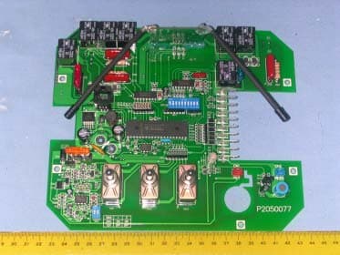
Click to zoom
Application Details
- Equipment Class
- CYY - Communications Receiver used w/Pt 15 Transmitter
- Date of Grant
- Mar 26, 2006
- Application Purpose
- Original Equipment
- Date of Application
- Mar 26, 2006
- Equipment Note
- Remote Control Receiver
- Frequency Range
- 433.94000000 - 433.94000000
- Company
- SPAL USA
- Country
- United States
Documents & Files
Document Text
Text extracted from the exhibit documents filed with the FCC. Open a document above to read the original.
Users Manual
FCC ID: KNF6RX FCC Compliance and Advisory Statement This device complies with Part 15 of the FCC rules. Operation is subject to the following two conditions: 1) this device may not cause harmful interference, and 2) this device must accept any interference received, including interference that may cause undesired operation. This equipment has been tested and found to comply with the limits for a Class B digital device, according to Part 15 of the FCC rules. These limits are designed to provide reasonable protection against harmful interference in a residential installation. This equipment generates, uses and can radiate radio frequency energy and if not installed and used in accordance with the instructions, may cause harmful interference to radio communications. However, there is no guarantee that interference will not occur in a particular installation. If this equipment does cause harmful interference to radio or television reception, which can be determined by turning the equipment off and on, the user is encouraged to try correct the interference by one or more of the following measures: 1.Reorient the receiving antenna. 2.Increase the separation between the equipment and receiver. 3.Connect the equipment into and outlet on a circuit different from that to which the receiver is connected. 4.Consult the dealer or an experienced radio/TV technician for help. Any special accessories needed for compliance must be specified in the instruction manual. Warning: A shielded-type power cord is required in order to meet FCC emission limits and also to prevent interference to the nearby radio and television reception. It is essential that only the supplied power cord be used. Use only shielded cables to connect I/O devices to this equipment. CAUSION: Any changes or modifications not expressly approved by the party responsible for compliance could void your authority to operate the equipment. Installation: 1) Mount the enclosure in a secure location. Select a location that will minimize the amount of wire needed and that is as shielded as possible from the elements. 2) Run a pair of wires (6 awg is recommended) from a 12 Volt battery (do not connect to the battery at this time) to the box and feed them in through one of the black wire glands. 3) Connect your positive battery wire to the “+” terminal on the case. 4) Connect your negative battery wire to the “-” terminal on the case. 5) Run a pair of wires (6 awg is recommended) from the first motor you wish to control to the box and connect them to the motor 1 outputs. 6) Repeat steps 5 for the optional second and third motors. 7) Connect the motor wires to the motors using the terminals provided. 8) Connect the battery wires to the battery, splicing the included circuit breaker into the positive wire as close to the battery as possible. Use the terminals provided. 9) Using one of the included keys, un-lock the keyed switch to allow the controls to operate. 10) Verify that the motors operate in the correct direction when the manual toggle switches are used. Swapping the two wires hooked to the back of each motor will reverse its rotation. 11) Verify that the first motor operates correctly when the “I” and “II” key fob buttons are pressed and held and that the second motor operates correctly when the “III” and “IV” key fob buttons are pressed and held. If the motors operate at the incorrect time check that the wires are connected to the proper output. Operation: The outputs may be controller via the front mounted toggle switches or the 6 button remote keyfob. The power in direction of the toggle switch corresponds to the odd numbered buttons on the keyfob. And the opposite toggle direction, power out, is consistent with the even numbered keyfob buttons. IMPORTANT Always have the function you are activating in sight during use to facilitate diagnosis of any possible mechanical or electrical problems. Input voltage selection, if your unit has been equipped with 24 volt contactors the dip switches on the 2 switch bank should both be in the ON position. If using on 12-volt equipment leave both these switches in the OFF position. Programming/Re-Programming Transmitter: Before you begin, here are some hints: • The included keyfobs are pre-programmed from the factory to match the included receiver. • Before beginning, gather all of the keyfobs that you wish to program. The receiver will store codes for up to four keyfobs, but all must be programmed at the same time. Programming an additional keyfob at a later date will erase all previously stored keyfob codes. • The receiver automatically exits programming mode if it detects no activity for 10 seconds. If this happens before you finish, you will need to start over at Step 1. Reading all the way through the instructions before beginning will help. Programming Instructions: 1) Turn the keyed switch on and wait for the solid green LED 2) Turn the key switch off/on rapidly 5 times. If the led goes out during the process, you are switching too slowly. Leave the key in the on position after the 5 th cycle. With the key in the on position the LED should now show solid red. 3) Press any button on the first keyfob until the LED on the receiver blinks. Repeat for any remaining keyfobs. 4) When finished, simply wait 10 seconds for the receiver to exit programming mode (the light will go back to solid green). If you have any questions, please call our Customer Service Department at 1-800-297-9905. Roll Rite 2574 School Road Alger, MI 48610
Block Diagram
Band pass Filter and Antennal Matching Network Radio Frequency Amplifier Demodulator Low Pass Filter CPU Automatic Gain Control Antenna MODEL: RR1101 Block Diagram =================================================
External Photos
Spectrum Research & Testing Lab., Inc. No. 101-10, Ling 8, Shan-Tong Li, Chung-Li City, Taoyuan, Taiwan, R.O.C. Photo Page: 1 of 11 PHOTOS OF EUT Spectrum Research & Testing Lab., Inc. No. 101-10, Ling 8, Shan-Tong Li, Chung-Li City, Taoyuan, Taiwan, R.O.C. Photo Page: 2 of 11 PHOTOS OF EUT Spectrum Research & Testing Lab., Inc. No. 101-10, Ling 8, Shan-Tong Li, Chung-Li City, Taoyuan, Taiwan, R.O.C. Photo Page: 3 of 11 PHOTOS OF EUT Spectrum Research & Testing Lab., Inc. No. 101-10, Ling 8, Shan-Tong Li, Chung-Li City, Taoyuan, Taiwan, R.O.C. Photo Page: 4 of 11 PHOTOS OF EUT Spectrum Research & Testing Lab., Inc. No. 101-10, Ling 8, Shan-Tong Li, Chung-Li City, Taoyuan, Taiwan, R.O.C. Photo Page: 5 of 11 PHOTOS OF EUT Spectrum Research & Testing Lab., Inc. No. 101-10, Ling 8, Shan-Tong Li, Chung-Li City, Taoyuan, Taiwan, R.O.C. Photo Page: 6 of 11 PHOTOS OF EUT Spectrum Research & Testing Lab., Inc. No. 101-10, Ling 8, Shan-Tong Li, Chung-Li City, Taoyuan, Taiwan, R.O.C. Photo Page: 7 of 11 PHOTOS OF EUT Spectrum Research & Testing Lab., Inc. No. 101-10, Ling 8, Shan-Tong Li, Chung-Li City, Taoyuan, Taiwan, R.O.C. Photo Page: 8 of 11 PHOTOS OF EUT Spectrum Research & Testing Lab., Inc. No. 101-10, Ling 8, Shan-Tong Li, Chung-Li City, Taoyuan, Taiwan, R.O.C. Photo Page: 9 of 11 PHOTOS OF EUT Spectrum Research & Testing Lab., Inc. No. 101-10, Ling 8, Shan-Tong Li, Chung-Li City, Taoyuan, Taiwan, R.O.C. Photo Page: 10 of 11 PHOTOS OF EUT Spectrum Research & Testing Lab., Inc. No. 101-10, Ling 8, Shan-Tong Li, Chung-Li City, Taoyuan, Taiwan, R.O.C. Photo Page: 11 of 11 PHOTOS OF EUT
ID Label/Location Info
Spectrum Research & Testing Lab., Inc. No. 101-10, Ling 8, Shan-Tong Li, Chung-Li City, Taoyuan, Taiwan, R.O.C. Sample of FCC ID Label The device is large enough for it to be placed warning statement on the device as follow: FCC ID: KNF6RX This device complies with Part 15 FCC Rules. Operation is subject to the following two conditions: (1) This device may not cause harmful interference. (2) This device must accept any interference received including interference that may cause undesired operation.
Internal Photos
Spectrum Research & Testing Lab., Inc. No. 101-10, Ling 8, Shan-Tong Li, Chung-Li City, Taoyuan, Taiwan, R.O.C. Photo Page: 1 of 11 PHOTOS OF EUT Spectrum Research & Testing Lab., Inc. No. 101-10, Ling 8, Shan-Tong Li, Chung-Li City, Taoyuan, Taiwan, R.O.C. Photo Page: 2 of 11 PHOTOS OF EUT Spectrum Research & Testing Lab., Inc. No. 101-10, Ling 8, Shan-Tong Li, Chung-Li City, Taoyuan, Taiwan, R.O.C. Photo Page: 3 of 11 PHOTOS OF EUT Spectrum Research & Testing Lab., Inc. No. 101-10, Ling 8, Shan-Tong Li, Chung-Li City, Taoyuan, Taiwan, R.O.C. Photo Page: 4 of 11 PHOTOS OF EUT Spectrum Research & Testing Lab., Inc. No. 101-10, Ling 8, Shan-Tong Li, Chung-Li City, Taoyuan, Taiwan, R.O.C. Photo Page: 5 of 11 PHOTOS OF EUT Spectrum Research & Testing Lab., Inc. No. 101-10, Ling 8, Shan-Tong Li, Chung-Li City, Taoyuan, Taiwan, R.O.C. Photo Page: 6 of 11 PHOTOS OF EUT Spectrum Research & Testing Lab., Inc. No. 101-10, Ling 8, Shan-Tong Li, Chung-Li City, Taoyuan, Taiwan, R.O.C. Photo Page: 7 of 11 PHOTOS OF EUT Spectrum Research & Testing Lab., Inc. No. 101-10, Ling 8, Shan-Tong Li, Chung-Li City, Taoyuan, Taiwan, R.O.C. Photo Page: 8 of 11 PHOTOS OF EUT Spectrum Research & Testing Lab., Inc. No. 101-10, Ling 8, Shan-Tong Li, Chung-Li City, Taoyuan, Taiwan, R.O.C. Photo Page: 9 of 11 PHOTOS OF EUT Spectrum Research & Testing Lab., Inc. No. 101-10, Ling 8, Shan-Tong Li, Chung-Li City, Taoyuan, Taiwan, R.O.C. Photo Page: 10 of 11 PHOTOS OF EUT Spectrum Research & Testing Lab., Inc. No. 101-10, Ling 8, Shan-Tong Li, Chung-Li City, Taoyuan, Taiwan, R.O.C. Photo Page: 11 of 11 PHOTOS OF EUT
Operational Description
FCC ID: KNF6RX Operational Description of the equipment This EUT was applied 12Vdc. And carrier frequency is 433.94MHz. The modulation type is ASK and in the 4KHz bit rate of transmission. When push/choose key switch, the Controller IC (PWM pin) will send a signal and local oscillator will on, then transmitting signal. When RX get a modulation signal: (1)The car computer will check the signal and demodulation the signal. (2)signals go through low pass filter and send signal to CPU. (3)CPU will process the signal. (4)Relative Relay in RX will on, then can control the PDA, phone, ..etc.. PRODUCT Automated Control and Entry System with Ignition (ACE with Ignition) MODEL NO. UT-KIT-001 POWER SUPPLY 12Vdc(Battery) CABLE N/A I/O PORT/INTERFACE N/A FREQUENCY BAND 433.94MHz CARRIER FREQUENCY 433.94MHz NUMBER OF CHANNEL 1 CHANNEL SPACING N/A RF OUTPUT POWER 10mW=10dBm I.F. & L.O. L.O. 433.94MHz MODULATION TYPE ASK BIT RATE OF TRANSMISSION 4 kHz antenna type Integral Antenna
Schematics
1 2 3 4 5 6 78 ABCD 8 7 6 5 4 3 2 1 D CBA Title Number Revision Size A3 Date: 19-Oct-2005 Sheet of File: E:\ ~1\SCH_DWG\S203032.SCH Drawn By: WINCH RF ( 433.92M ) 1 Lai N OTE: ( 1 ) FRE Q UENCY : 433.92MHZ . 1.0 Drawn By : Enginner : Checked By : On board C1 2P7 C3 1P5 C22P7 C4 1P5 On board C5 27P Q1 PBR951 R2 560R R3 100K L1 1UH C8470P C6 2P7 Q2PBR951 R4 47K R6 15K L2 2.2UH C10 2P L3 1.5T C11 4P C7 47P R5 39K C12 330P R7 6K8 C9 470P R8 3K3 C14 472 ANTENNA U1 : NS358 R9 2K2 56 7 C15 68P R10 1M5 R12 2K2 C16105 R11 100K TEST POINT 1 23 R13 10K R15 10M C18104 R14 68K C17 102 C19 104 48 R16 2K2 DATA O/P +5V U1A U1B C13 47U/10V R1 56R +5V P2030362 8 IN 1 YS-254WS
Schematics
55 44 33 22 11 D D C C B B A A RB5RB4 (JA4)(JA5)(JA3)(JA2) RB0RB1 MLRB7RB6 RB3 F1BAD F1BAD RA1 RE2 RD6 RD5RD4RE1RE0RA5RA4 RC7 RC2RC3RC5 RC1 RA2 RB6 (JA7)(JA6) RA2 RE2 RB2 RD3RD2RD1 RC0 RC6RC4 RB7 RD0 OP7OP8 OP2 OP3 OP4 OP5 OP6 LIGHT RA4 RC7RC4 OSC1 RE1 RA3RB6 RA3 RB3RA0 ML RC2 RB5RB2RB0RA2 RC5RC3RC1RE2RE0 ML RB7RA5 RD6RD3RD4RC6RD7RD1RD0 RB1 RD2 OSC2 RA1RB4 RC0RD5 VCC VCC VCC VCC VCC VCC VCC VB+ V1 V2 VC+ VCC VCC VCC VCC V4 V1 VCC V2 VCC VCC V4 VB+ VB+ V3 V3 VCC VC+ TitleSize Document Number R e v D ate: Sheet of RR1101 2.0 RR1101 A3 11 Tuesday, September 13, 2005 PROG. TOGGLE SW. 35V 25V 35V 25V P1P2 S2050085 P2050077 (JA1) A1 B1 A2 B2 A3B3 OSC1 OSC2 (CN5) (CN5) (CN5) (CN5) (CN6)(CN6) D11 D12 SM4007 SM4007 RA0 1% 1% (CN5) (CN6) (CN5) (CN5) (JA10) (JA9) (CN5) (JA8) (CN6) OP1 U1 P3596L-5V 12 35 4 VIN OUT GND ON/OFF FB 1% RD7 1% R1~R61, C1~C18, D1~D24, ZD1~ZD10, Q1~Q6,RV1~RV8, RL1~RL7, F1~F3, U1~U6, RP1~RP5,SW1~SW5, L1~L2, Y1, LED D5~D10 ==> SM4007 P2030362 F=433.9 2MHz RED BLUE HT7550-1 U7 Vin Vout GND COIL: 5V COIL: 5V COIL: 5V COIL: 5V COIL: 5VCOIL: 5VCOIL: 5V RF_MODULE 123 R2512K D20 SM5399 R3810K R9 22K RV2 330T551 D3 BAV70 D9 R36 10K D5 R48 4K7 C17 104 R3722K R49 4K7 R13 10K C3 104 RV4 330T551 Z D3 3V3 C15105/ 250V R2010R C14105/ 250V D22 SM5399 SW13P 123 D15 SM4007 Q5 2907 C7 104 R53 4K7 CN3 123456 C10 104 L11.65mH R17 1K RL5 833H-1C-C C13 10uF R31 10K RP410K 7P A TYPE 2 2 3 3 4 4 5 5 6 6 7 7 1 1 D17 SM5399 R43470 RP510K 7P A TYPE 2 2 3 3 4 4 5 5 6 6 7 7 1 1 D8 R22470R -+ U2B LM358 56 7 84 R3 10K C9 104 R393K3 RL2 833H-1C-C RV6 330T551 Z D4 3V3 D7 CN1 2.5/2P 12 R47 4K7 R2 15K ZD1 SR540 RP3 2K2 5P A TYPE 2 2 3 3 4 4 5 5 1 1 Q1 B772 R44 10R C18104 R5922R/ 2W R6 2K2 R5 10K U5 2003A A 1 A 16 B 2 B 15 C 3 C 14 D 4 D 13 E 5 E 12 F 6 F 11 G 7 G 10 GND 8 VCC 9 4K7 R7 CN22.5/2P 12 Z D6 3V3 U3 2003A A 1 A 16 B 2 B 15 C 3 C 14 D 4 D 13 E 5 E 12 F 6 F 11 G 7 G 10 GND 8 VCC 9 U4 PIC16F74-I/P RE0/RD/AN5 8 RE1/WR/AN6 9 RE2/CS/AN7 10 GND 12 OSC2/CLKOUT 14 RC0/T1OSO/T1CKI 15 RC1/T1OSI/CCP2 16 RC2/CCP1 17 RC3/SCK/SCL 18 RD0/PSP0 19 RD1/PSP1 20 RD2/PSP2 21 RD3/PSP3 22 RC4/SDI/SDA 23 RC5/SDO 24 RC6/TX/CK 25 RC7/RX/DT 26 RD4/PSP4 27 RD5/PSP5 28 RD6/PSP6 29 RD7/PSP7 30 GND 31 MCLR/VPP 1 OSC1/CLKIN 13 RA0/AN0 2 RA1/AN1 3 RA2/AN2 4 RA3/AN3/VREF 5 RA4/TOCKI 6 RA5/AN4/SS 7 RBO/INT 33 RB1 34 RB2 35 RB3/PGM 36 RB4 37 RB5 38 RB6/PGC 39 RB7/PGD 40 VDD 11 VDD 32 R29 100K D24 SM4007 D16 SM4007 RV8 330T551 C12 10uF/ 25V R4010K R11 10K R42220 D19 SM5399 RV1 14D220K ZD9 27V/ 1W C11 224/100V R32 10K C2 1000uF R50 4K7 Q2 C1623 DIPSW DI-10S 1 2 3 4 5 6 12 11 10 9 8 7 R10 10K R34 10K RLED SW4 DIPSW*02 R1510K Y1 4MHz R1847K RV3 330T551 -+ U2A LM358 32 1 84 R54 4K7 R1610K C8 104 D1 BAW56 SW23P 123 Z D2 3V3 R1210K RP1 10K 7P A TYPE 2 2 3 3 4 4 5 5 6 6 7 7 1 1 ZD8 5V6/ 1W D21 SM5399 R45 10R F15A RP2 10K 7P A TYPE 2 2 3 3 4 4 5 5 6 6 7 7 1 1 D10 C16 105/ 250V D6 R130K R56 4K7 R46 4K7 D14 1N5404 RL3 833H-1C-C 10K R8 RV5 330T551 BUZZER 1 2 RL7 833H-1C-C RL4 833H-1C-C C610uF R26 100K R1410K D23 SM5399 R23470R RL6 833H-1C-C Q3 2N2222 F3 15A Q6 B772 R35 10K RL1 833H-1C-C R27220K C5 104 R3022K Q4 2N2222 Z D5 3V3 R51 4K7 RV7 330T551 D4 BAS32 R6022R/ 2W R4110K R52 4K7 D18 SM5399 DIPSWDI-10S 1 2 3 4 8 7 6 5 D13 BAS32 R28 220K R57 4K7 ZD10 5V1 L2 33uH R55 4K7 R19 100K GLED R4 10K C4 470uF R5822R/ 2W R2430K ZD7 3V3 R21 1K SW3 3P 123 R33 10K D2 BAV70 F2 10A C1104 U6 93C46 DI 3 DO 4 ORG 6 CLK 2 CS 1 VCC 8
Test Report
Spectrum Research & Testing Lab., Inc. No. 101-10, Ling 8, Shan-Tong Li, Chung-Li City, Taoyuan, Taiwan, R.O.C. TEST REPORT Reference No.:A05102107 Report No.:FCBA05102107 FCC ID:KNF6RX Page:2 of 11 Date:Nov. 14, 2005 Table of Contents 1. DOCUMENT POLICY AND TEST STATEMENT ................................................ 3 1.1 DOCUMENT POLICY ........................................................................................ 3 1.2 TEST STATEMENT ............................................................................................ 3 1.3 EUT MODIFICATION ......................................................................................... 3 2. DESCRIPTION OF EUT AND TEST MODE....................................................... 4 2.1 GENERAL DESCRIPTION OF EUT................................................................... 4 2.2 DESCRIPTION OF EUT INTERNAL DEVICE.................................................... 4 2.3 DESCRIPTION OF TEST MODE ....................................................................... 4 2.4 DESCRIPTION OF SUPPORT UNIT ................................................................. 5 3. DESCRIPTION OF APPLIED STANDARDS ...................................................... 5 3.1 EUT OPERATING CONDITION ......................................................................... 5 4. RADIATED EMISSION TEST ............................................................................. 6 4.1 RADIATED EMISSION LIMIT............................................................................. 6 5.2 TEST EQUIPMENT............................................................................................ 6 4.3 TEST SET-UP .................................................................................................... 7 4.4 TEST PROCEDURE .......................................................................................... 8 4.5 EUT OPERATING CONDITION ......................................................................... 8 4.6 RADIATED EMISSION TEST RESULT .............................................................. 9 6. PHOTOS OF TESTING .................................................................................... 10 7. TERMS OF ABRIVATION ..................................................................................11 Spectrum Research & Testing Lab., Inc. No. 101-10, Ling 8, Shan-Tong Li, Chung-Li City, Taoyuan, Taiwan, R.O.C. TEST REPORT Reference No.:A05102107 Report No.:FCBA05102107 FCC ID:KNF6RX Page:3 of 11 Date:Nov. 14, 2005 1. DOCUMENT POLICY AND TEST STATEMENT 1.1 DOCUMENT POLICY - The report shall not be reproduced except in full, without the written approval of SRT Lab, Inc. - The report must not be used by the applicant to claim that the product is endorsed by NVLAP, TÜV, NEMKO and SRT. - The NVLAP logo applies only to the applicable standards specified in this report. 1.2 TEST STATEMENT - The test results in the report apply only to the unit tested by SRT Lab. - There was no deviation from the requirements of test standards during the test. - AC power source, 120 Vac/60 Hz, was used during the test. 1.3 EUT MODIFICATION - No modification in SRT Lab. Spectrum Research & Testing Lab., Inc. No. 101-10, Ling 8, Shan-Tong Li, Chung-Li City, Taoyuan, Taiwan, R.O.C. TEST REPORT Reference No.:A05102107 Report No.:FCBA05102107 FCC ID:KNF6RX Page:4 of 11 Date:Nov. 14, 2005 2. DESCRIPTION OF EUT AND TEST MODE 2.1 GENERAL DESCRIPTION OF EUT PRODUCT Relay Kit for 3 Motors w/ Wireless Remote Control MODEL NO. RR-19805 POWER SUPPLY DC from an external power supply CABLE N/A TYPE Prototype NOTE : For more detailed information, please refer to the EUT’s specification or user’s manual provided by manufacturer. 2.2 DESCRIPTION OF EUT INTERNAL DEVICE DEVICE BRAND/MAKERMODEL # FCC ID/DOC REMARK N/A 1. The highest clock is 4MHz. 2. Frequency range to be measured. Radiated emission is 30 MHz to 1 GHz. 2.3 DESCRIPTION OF TEST MODE N/A (It is only applicable to more than one test mode.) Spectrum Research & Testing Lab., Inc. No. 101-10, Ling 8, Shan-Tong Li, Chung-Li City, Taoyuan, Taiwan, R.O.C. TEST REPORT Reference No.:A05102107 Report No.:FCBA05102107 FCC ID:KNF6RX Page:5 of 11 Date:Nov. 14, 2005 2.4 DESCRIPTION OF SUPPORT UNIT The EUT was configured by the requirement of ANSI C63.4:2003 and CISPR 22:2003. All interface ports were connected to the appropriate support units via specific cables. The support units and cables are listed below. NO DEVICE BRAND MODEL #FCC ID/DOCCABLE 1 DC POWER SUPPLY LURICH RPS-512MB N/A 1.5m unshielded power cable NOTE : For the actual test configuration, please refer to the photos of testing. 3. DESCRIPTION OF APPLIED STANDARDS The EUT is a kind of ITE and according to the specifications provided by the applicant, it must comply with the requirements of the following standards: 47 CFR Part 15 Subpart B, Class B All tests have been performed and recorded as per the above standards. 3.1 EUT OPERATING CONDITION 1.Power on and normal work. Spectrum Research & Testing Lab., Inc. No. 101-10, Ling 8, Shan-Tong Li, Chung-Li City, Taoyuan, Taiwan, R.O.C. TEST REPORT Reference No.:A05102107 Report No.:FCBA05102107 FCC ID:KNF6RX Page:6 of 11 Date:Nov. 14, 2005 4. RADIATED EMISSION TEST 4.1 RADIATED EMISSION LIMIT CISPR 22:2003 limits of radiated emission measurement for frequency below 1000 MHz Class A (at 10m) Class B (at 10m) FREQUENCY (MHz) dBμV/m dBμV/m 30 – 230 40 30 230 - 1000 47 37 NOTE: 1. The lower limit shall apply at the transition frequencies. 2. Emission level (dBμV/m) = 20 log Emission level (μV/m). 5.2 TEST EQUIPMENT The following test equipment was used during the radiated emission test: EQUIPMENT/ FACILITIES SPECIFICATIONSMANUFACTURER MODEL#/ SERIAL# DUE DATE OF CAL. & CAL. CENTER EMI TEST RECEIVER 20 kHz TO 1 GHz ROHDE & SCHWARZ ESCS30/ 830245/012 OCT. 2006 ETC BI-LOG ANTENNA 25 MHz TO 2 GHz EMCO 3143 9509-1152 JUN. 2006 SRT OATS 3 – 10 M MEASUREMENT SRT SRT-1 DEC. 2005 SRT COAXIAL CABLE 25M…
Text truncated - open the document above for the full version.
Test Setup Photos
Spectrum Research & Testing Lab., Inc. No. 101-10, Ling 8, Shan-Tong Li, Chung-Li City, Taoyuan, Taiwan, R.O.C. TEST REPORT Reference No.:A05102107 Report No.:FCBA05102107 FCC ID:KNF6RX Page:2 of 11 Date:Nov. 14, 2005 Table of Contents 1. DOCUMENT POLICY AND TEST STATEMENT ................................................ 3 1.1 DOCUMENT POLICY ........................................................................................ 3 1.2 TEST STATEMENT ............................................................................................ 3 1.3 EUT MODIFICATION ......................................................................................... 3 2. DESCRIPTION OF EUT AND TEST MODE....................................................... 4 2.1 GENERAL DESCRIPTION OF EUT................................................................... 4 2.2 DESCRIPTION OF EUT INTERNAL DEVICE.................................................... 4 2.3 DESCRIPTION OF TEST MODE ....................................................................... 4 2.4 DESCRIPTION OF SUPPORT UNIT ................................................................. 5 3. DESCRIPTION OF APPLIED STANDARDS ...................................................... 5 3.1 EUT OPERATING CONDITION ......................................................................... 5 4. RADIATED EMISSION TEST ............................................................................. 6 4.1 RADIATED EMISSION LIMIT............................................................................. 6 5.2 TEST EQUIPMENT............................................................................................ 6 4.3 TEST SET-UP .................................................................................................... 7 4.4 TEST PROCEDURE .......................................................................................... 8 4.5 EUT OPERATING CONDITION ......................................................................... 8 4.6 RADIATED EMISSION TEST RESULT .............................................................. 9 6. PHOTOS OF TESTING .................................................................................... 10 7. TERMS OF ABRIVATION ..................................................................................11 Spectrum Research & Testing Lab., Inc. No. 101-10, Ling 8, Shan-Tong Li, Chung-Li City, Taoyuan, Taiwan, R.O.C. TEST REPORT Reference No.:A05102107 Report No.:FCBA05102107 FCC ID:KNF6RX Page:3 of 11 Date:Nov. 14, 2005 1. DOCUMENT POLICY AND TEST STATEMENT 1.1 DOCUMENT POLICY - The report shall not be reproduced except in full, without the written approval of SRT Lab, Inc. - The report must not be used by the applicant to claim that the product is endorsed by NVLAP, TÜV, NEMKO and SRT. - The NVLAP logo applies only to the applicable standards specified in this report. 1.2 TEST STATEMENT - The test results in the report apply only to the unit tested by SRT Lab. - There was no deviation from the requirements of test standards during the test. - AC power source, 120 Vac/60 Hz, was used during the test. 1.3 EUT MODIFICATION - No modification in SRT Lab. Spectrum Research & Testing Lab., Inc. No. 101-10, Ling 8, Shan-Tong Li, Chung-Li City, Taoyuan, Taiwan, R.O.C. TEST REPORT Reference No.:A05102107 Report No.:FCBA05102107 FCC ID:KNF6RX Page:4 of 11 Date:Nov. 14, 2005 2. DESCRIPTION OF EUT AND TEST MODE 2.1 GENERAL DESCRIPTION OF EUT PRODUCT Relay Kit for 3 Motors w/ Wireless Remote Control MODEL NO. RR-19805 POWER SUPPLY DC from an external power supply CABLE N/A TYPE Prototype NOTE : For more detailed information, please refer to the EUT’s specification or user’s manual provided by manufacturer. 2.2 DESCRIPTION OF EUT INTERNAL DEVICE DEVICE BRAND/MAKERMODEL # FCC ID/DOC REMARK N/A 1. The highest clock is 4MHz. 2. Frequency range to be measured. Radiated emission is 30 MHz to 1 GHz. 2.3 DESCRIPTION OF TEST MODE N/A (It is only applicable to more than one test mode.) Spectrum Research & Testing Lab., Inc. No. 101-10, Ling 8, Shan-Tong Li, Chung-Li City, Taoyuan, Taiwan, R.O.C. TEST REPORT Reference No.:A05102107 Report No.:FCBA05102107 FCC ID:KNF6RX Page:5 of 11 Date:Nov. 14, 2005 2.4 DESCRIPTION OF SUPPORT UNIT The EUT was configured by the requirement of ANSI C63.4:2003 and CISPR 22:2003. All interface ports were connected to the appropriate support units via specific cables. The support units and cables are listed below. NO DEVICE BRAND MODEL #FCC ID/DOCCABLE 1 DC POWER SUPPLY LURICH RPS-512MB N/A 1.5m unshielded power cable NOTE : For the actual test configuration, please refer to the photos of testing. 3. DESCRIPTION OF APPLIED STANDARDS The EUT is a kind of ITE and according to the specifications provided by the applicant, it must comply with the requirements of the following standards: 47 CFR Part 15 Subpart B, Class B All tests have been performed and recorded as per the above standards. 3.1 EUT OPERATING CONDITION 1.Power on and normal work. Spectrum Research & Testing Lab., Inc. No. 101-10, Ling 8, Shan-Tong Li, Chung-Li City, Taoyuan, Taiwan, R.O.C. TEST REPORT Reference No.:A05102107 Report No.:FCBA05102107 FCC ID:KNF6RX Page:6 of 11 Date:Nov. 14, 2005 4. RADIATED EMISSION TEST 4.1 RADIATED EMISSION LIMIT CISPR 22:2003 limits of radiated emission measurement for frequency below 1000 MHz Class A (at 10m) Class B (at 10m) FREQUENCY (MHz) dBμV/m dBμV/m 30 – 230 40 30 230 - 1000 47 37 NOTE: 1. The lower limit shall apply at the transition frequencies. 2. Emission level (dBμV/m) = 20 log Emission level (μV/m). 5.2 TEST EQUIPMENT The following test equipment was used during the radiated emission test: EQUIPMENT/ FACILITIES SPECIFICATIONSMANUFACTURER MODEL#/ SERIAL# DUE DATE OF CAL. & CAL. CENTER EMI TEST RECEIVER 20 kHz TO 1 GHz ROHDE & SCHWARZ ESCS30/ 830245/012 OCT. 2006 ETC BI-LOG ANTENNA 25 MHz TO 2 GHz EMCO 3143 9509-1152 JUN. 2006 SRT OATS 3 – 10 M MEASUREMENT SRT SRT-1 DEC. 2005 SRT COAXIAL CABLE 25M…
Text truncated - open the document above for the full version.
Contact Information
Applicant
Dan McNeal(QC/Engineering Manager)
Test Firm
Spectrum Research & Testing Laboratory, Inc.Cheng Ho
Technical Specifications
| # | Rule Parts | Frequency Range | Power Output |
|---|---|---|---|
| 1 | 15B | 433.94 MHz - 433.94 MHz | - |
Other Applications from SPAL USA
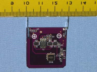
KNF4TX433
Oct 26, 2005AUTOMATED CONTROL
Equipment Class
DSC - Part 15 Security/Remote Control Transmitter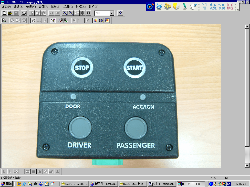
KNFUTRX
Sep 28, 2005Automated Control
Equipment Class
DXX - Part 15 Low Power Communication Device Transmitter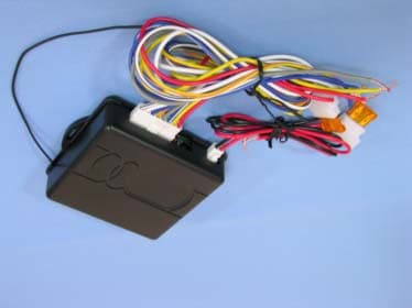
KNFRCU6RX
Sep 26, 2004REMOTE CONTOLLER (RX)
Equipment Class
CXX - Communications Rcvr for use w/ licensed Tx and CBs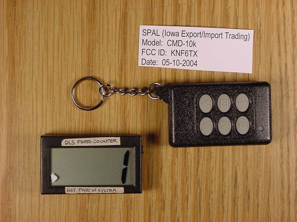
KNF6TX
Jul 05, 2004Automotive Aftermarket Transmitter
Equipment Class
DSC - Part 15 Security/Remote Control Transmitter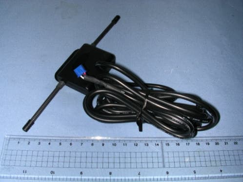
KNFAIRRX
May 09, 2004air kit (rx)
Equipment Class
CRR - Superregenerative Receiver