KNFUTRXAutomated Control
SPAL USA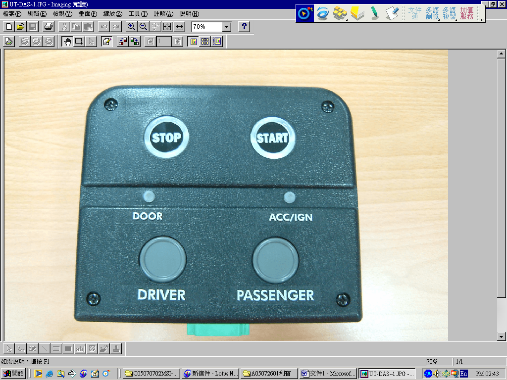
Click to zoom
Application Details
- Equipment Class
- DXX - Part 15 Low Power Communication Device Transmitter
- Date of Grant
- Sep 28, 2005
- Application Purpose
- Original Equipment
- Date of Application
- Sep 28, 2005
- Equipment Note
- Automated Control
- Frequency Range
- 433.94000000 - 433.94000000
- Company
- SPAL USA
- Country
- United States
Documents & Files
Document Text
Text extracted from the exhibit documents filed with the FCC. Open a document above to read the original.
Users Manual
ACE Programming Guide 1. ACE Main Module 2. Jumper 3. Transmitter Unit 4. Jumper Socket 5. Programming Button New Owner/Operator Vehicles Owner/operator prepped vehicles are identified by the Black Jumper in the ACE Main Module mounted on the overhead shelf on the passenger side (Fig. 1). •If the vehicle is equipped with an alarm, remove the Jumper and press button #1 on a trained transmitter to ARM the system. Keep the Jumper (Fig. 2) in a secure location for training new transmitters should any get lost or stolen. •If the vehicle is NOT equipped with an alarm, remove the Jumper (even if the vehicle is delivered fully operational) and store it in a secure location for training replacement transmitters. NOTE: The vehicle will not respond to a transmitter (key fob, Fig. 3) unless the transmitter is correctly programmed to the specific vehicle. NOTE: Owner/operator vehicles with alarms are NOT ARMED when shipped from Utilimaster. To arm the system, remove the Black Jumper from the Main Module upon receiving the vehicle and press button #1 on a trained transmitter . IMPORTANT: ALWAYS tag and store ALL Jumpers in a secure location when not using them to train a vehicle. For additional information, see the ACE (Automated Control and Entry) System Opera- tion and Service Manual (Part Number 03102977). This manual describes the other features of the optional ignition control and alarm system. NOTE: The information in this guide is generic. Details in the illustrations and procedures may differ from those in your vehicle. Use this information as a guideline where applicable. New Fleet Vehicles Fleet prepped vehicles are identified by the empty Jumper socket in the ACE Main Module mounted on the overhead shelf on the passenger side and the alarms (if so equipped) ARE active. It is advised that new Jumpers be inserted into all new vehicles and the transmitters be trained upon arrival. Continue on the back page for instructions on how to train transmitters and change Jumpers. ACE Programming Guide ©2005, Utilimaster. ® printed Aug 2005 in U.S.A. Utilimaster Corporation, 65906 State Road 19, P.O. Box 585, Wakarusa, Indiana, 46573–0585. ACE Programming Guide (Part Number 03102976) DRAFT Training Transmitters IMPORTANT: When training new transmitters ALL of the previously trained transmitters will be erased from the system memory, so have ALL required transmitters available before proceeding. NOTE: All system functions are disabled while in training mode. NOTE: Up to 10 transmitters may be trained at one time per vehicle. NOTE: Before starting work, read and understand all of the instructions 1.Stop the engine, and be certain the vehicle is not in the accessory mode. 2.Remove the jumper socket cover from the Main Module and plug the currently programmed (or transport) Jumper into the Main Module socket (Fig. 4). (The speaker, if equipped, will make a short, low-tone beep followed by a short, high-tone beep.) 3.Press and release the programming button 5 times (Fig. 5). (The speaker will make a single high-tone beep and the Green programming LED will light.) 4.Press button #1 on the first transmitter. (The speaker beeps once and the programming LED will flash once to con- firm the transmitter is recognized.) 5.Repeat step 4 to train additional transmitters up to a maximum of 10 per vehicle. NOTE: The system will wait up to 5 seconds between transmitters being trained. If no additional transmitters are detected, the system will time out automatically. Upon exiting, the speaker will beep and the LED will flash once for each trained transmitter. When the LED has finished flashing, it remains lit for another 2.5 seconds, then turns off. Changing Jumpers IMPORTANT: When a new Jumper is used to train a vehicle, the old jumper and ALL Transmitters are erased from the system memory. Transmitters must be retrained. NOTE: Before starting work, read and understand all of the instructions 1.Stop the engine, and be certain the vehicle is not in the accessory mode. 2.Plug the currently programmed Jumper into the Main Module Jumper socket. (The speaker will make a short, low- tone beep followed by a short, high-tone beep.) 3.Press and hold the programming button (Fig. 7) for 5 seconds. (The speaker will beep three times and the Green programming LED will flash. IMPORTANT: You only have 10 seconds to complete the next two steps. 4.Remove the current Jumper and replace it with a new Jumper. 5.Press the programming button on the Main Module once. (If the new Jumper was recognized, the programming LED will light for 3 seconds indicating the system is fully functional. If the new Jumper was not recognized, the speaker beeps for one second and the programming LED turns off shortly after. This indicates the old Jumper information is still trained into the system and the programming procedure must be repeated.) IMPORTANT: After the new Jumper is confirmed ALL previous transmitters are no longer recognized and will need to be retrained to the vehicle. 6.Train transmitters to the vehicle. (See above section.) IMPORTANT: If the socket cover is not installed, the main module is not sealed properly and is susceptible to damage. IMPORTANT: ALWAYS tag and store ALL Jumpers in a secure location when not using them to train a vehicle. For additional information, see the ACE (Automated Control and Entry) System Operation and Service Manual (Part Number 03102977). This manual describes the other features of the optional ignition control and alarm system. For additional information, browse www.utilimaster.com/ace. From there, the ACE (Automated Control and Entry) System Operation and Service Manual (Part Number 03102977) can be downloaded in Adobe Acrobat format. Also, a paper copy can be ordered by emailing [email protected], calling 800–237–7806 (574–862–3219), or faxing 574–862–7637. This manual describes the other features of the optional ignition control and alarm system.
Block Diagram
Band pass Filter and Antenna Matching Network Radio Frequency Amplifier Demodulator Low Pass Filter CPU Automatic Gain Control Antenna MODEL: UT-KIT Block Diagram =================================================
Block Diagram
SW1 SW2 SW3 SW4 ENCODER U1 Q1 PWM & OSCILLATOR ANTENNA +12V BATTERY ADDRESS CODE MODEL: TX174AHCS4 Block Diagram ==========================================================
Operational Description
©2005, Utilimaster. ® printed Aug 2005 in U.S.A. Utilimaster Corporation, 65906 State Road 19, P.O. Box 585, Wakarusa, Indiana, 46573–0585. ACE Programming Guide (Part Number 03102976) DRAFT Training Transmitters IMPORTANT: When training new transmitters ALL of the previously trained transmitters will be erased from the system memory, so have ALL required transmitters available before proceeding. NOTE: All system functions are disabled while in training mode. NOTE: Up to 10 transmitters may be trained at one time per vehicle. NOTE: Before starting work, read and understand all of the instructions 1.Stop the engine, and be certain the vehicle is not in the accessory mode. 2.Remove the jumper socket cover from the Main Module and plug the currently programmed (or transport) Jumper into the Main Module socket (Fig. 4). (The speaker, if equipped, will make a short, low-tone beep followed by a short, high-tone beep.) 3.Press and release the programming button 5 times (Fig. 5). (The speaker will make a single high-tone beep and the Green programming LED will light.) 4.Press button #1 on the first transmitter. (The speaker beeps once and the programming LED will flash once to con- firm the transmitter is recognized.) 5.Repeat step 4 to train additional transmitters up to a maximum of 10 per vehicle. NOTE: The system will wait up to 5 seconds between transmitters being trained. If no additional transmitters are detected, the system will time out automatically. Upon exiting, the speaker will beep and the LED will flash once for each trained transmitter. When the LED has finished flashing, it remains lit for another 2.5 seconds, then turns off. Changing Jumpers IMPORTANT: When a new Jumper is used to train a vehicle, the old jumper and ALL Transmitters are erased from the system memory. Transmitters must be retrained. NOTE: Before starting work, read and understand all of the instructions 1.Stop the engine, and be certain the vehicle is not in the accessory mode. 2.Plug the currently programmed Jumper into the Main Module Jumper socket. (The speaker will make a short, low- tone beep followed by a short, high-tone beep.) 3.Press and hold the programming button (Fig. 7) for 5 seconds. (The speaker will beep three times and the Green programming LED will flash. IMPORTANT: You only have 10 seconds to complete the next two steps. 4.Remove the current Jumper and replace it with a new Jumper. 5.Press the programming button on the Main Module once. (If the new Jumper was recognized, the programming LED will light for 3 seconds indicating the system is fully functional. If the new Jumper was not recognized, the speaker beeps for one second and the programming LED turns off shortly after. This indicates the old Jumper information is still trained into the system and the programming procedure must be repeated.) IMPORTANT: After the new Jumper is confirmed ALL previous transmitters are no longer recognized and will need to be retrained to the vehicle. 6.Train transmitters to the vehicle. (See above section.) IMPORTANT: If the socket cover is not installed, the main module is not sealed properly and is susceptible to damage. IMPORTANT: ALWAYS tag and store ALL Jumpers in a secure location when not using them to train a vehicle. For additional information, see the ACE (Automated Control and Entry) System Operation and Service Manual (Part Number 03102977). This manual describes the other features of the optional ignition control and alarm system. For additional information, browse www.utilimaster.com/ace. From there, the ACE (Automated Control and Entry) System Operation and Service Manual (Part Number 03102977) can be downloaded in Adobe Acrobat format. Also, a paper copy can be ordered by emailing [email protected], calling 800–237–7806 (574–862–3219), or faxing 574–862–7637. This manual describes the other features of the optional ignition control and alarm system.
Schematics
55 44 33 22 11 D D C C B B A A RC6 DOUT RB3 RA3 RA4 RB6RB7ML DIN RC7 RB6RB5RB4RB7 RA2RA0 RA1 OSC1 OSC2 RB2 RB4 OSC2 RC4RC6 RA5 OSC1 RC3 RB0RA0RA4 RC1RC2 RB6RA1RB3RB7 RC0 RB2RA2RB5 ML RB1 RC5 RA3 RC7 RB0 RB1 VCC +12V VCC VCC VCCVCCVCC VCC ACC_IN IGN OUTPUT STARTER OUTPUT ACCOP VCC VCC VCC +12V +12V TitleSize Document Number R e v D ate: Sheet of UT-DASH-001 A3 11 W ednesday, July 27, 2005 PROG. DRIVERDOORRELEASEPASSENGERDOORRELEASESTOP IGN_ ON_LED START DOOR_ OPEN_LED ACC_ ON_LED PGDPGC P205 0127 P205 0133 DATA_IN DATA_OUT 25V 25V 16V S2050144 STOP ML Retain Retain /100V /100V /100V /100V 100V 100V START Retain P2050127 P2050127 P2050127 1W P2050127 CN1 12 LED14 GREEN 2 1 R5 10K R211K CN2 123456 D2 SM4007 LED13YELLOW 2 1 R8 10K LED9 2 1 R301K R4310K R47 47K R1 47R/2W R281K R221K R13 1R8 LED10 GREEN 2 1 R7 1R8 R3 1K LED5 2 1 Q2 MPSA13 R261K R271K D3 SM4007 D1 SM4004 Q4 MPSA13 LED7 2 1 R311K R1810K R321K C1 1000uF R231K R3910K RV2 330T551 C6 104 R6 47K LED4 RED 2 1 Q1 2N2222A R33 470R R9 47K Q82N2222A C4 104 ZD124V LED15 2 1 LED1 2 1 Q7 C945 R101R8 D4 SM4007 R29 1K R1747K LED6 2 1 R15 1K C2 1000uF R4010K R20 470R R1410K LED2 2 1 LED12 2 1 C7 104 RV3 330T551 Q92N2222A R35470R R241K R4410K R4110K C3 100uF R11 10K C8 104 C5 104 Q3 C945 R3810K R1610K R34 470R Y1 4MHz Q5 C945 RV1 14D220K R42 10K LED3 2 1 LED11 2 1 R2 10K R19 470R Q6 MPSA13 R3610K U1 C78L05 IN 2 OUT 3 LED8 2 1 R45 47K R4610K RV4 7D220 R251K C9 104 U2 PIC16F73 MCLR/VPP/RE3 1 RA0/AN0 2 RA1/AN1 3 RA2/AN2/VREF- 4 RA3/AN3/VREF+ 5 RA4/T0CKI/C1OUT 6 RA5/SS/LVDIN/AN4/C2O 7 OSC1/CLKIN/RA7 9 OSC2/CLKOUT/RA6 10 RC0/T1OSO/T1CKI 11 RC1/T1OSI/CCP2 12 RC2/CCP1 13 RC3/SCK/SCL 14 RC4/SDI/SDA 15 RC5/SDO 16 RC6/TX/CK 17 RC7/RX/DT 18 VDD 20 RB0/INT/AN12 21 RB1/AN10 22 RB2/AN8 23 RB3/CCP2/AN9 24 RB4/AN11 25 RB5/AN13/CCP3 26 RB6/PGC 27 RB7/PGD 28 R1247K R37 10K
Schematics
55 44 33 22 11 D D C C B B A A OSC2 IGNIN BELT IGNON OSC1 IGNON RC6 DOUT PTR RC3 RC4 RA0 RA1 RA2 RB3RB4RB5RB0RB1RB2 RC0RC1 RA3RA2RA1RA0 RC6RC7RE0RE1RE2RC2RC3RC4RC5 RB3RA4RA5RB4RB5RB7RB0RB1RB2 ML RD0RD1RD2RD3RD4RD5RD6RD7 RB6 OSC1OSC2 ML RB7RB6 ML RD0RD1RD2RD3RD4RD5 RA3RA4RA5 DIN RC7 RC1 RC0 VCC VCC +12V VCC DRIVER_SOLENOID_OP+ BULKHEAD_SOLENOID _OP+ +12V CARGO_SOLENOID_OP+CARGO_SOLENOID_OP- DRIVER_SOLENOID_OP- GND +12V VB+ +12V VCC VCC DOME LIGHT VB+ BULKHEAD_SOLENOID_OP- PASSENGER_SOLENOI D_OP- PASSENGER_SOLENO ID_OP+ +12V VCC VCC VCC VCC VCC +12V VB+ VBA SIREN A VBA SIREN B NEGATIVE I/P VBA VBA TitleSize Document Number R e v D ate: Sheet of 3.0 A3 11 Thursday, June 16, 2005 Utilimaster Retrofit Kit Main boardURK309-1 BLK_DOOR SENSORCARGO_DOOR SENSOR BULKHEAD DOOR CARGO DOOR PROG_BUTTON PROGRAMMING JUMPER MOTION SENSOR DRV_DOOR SENSORPSG_DOOR SENSOR PROGRAMMING PORT NC 66 2 7 3 NC 5 2 NCNC 1 3 NC U6 U5 41 NDS8858HNDS8858H 8 5 7 NC 8 4 25V 25V 25V 1/2W 16V RESERVE RESERVE POSITIVE I/P RELEASE BUTTON RELEASE BUTTON 1/2W ( P2030362 , f = 433.92MHz ) ( PROG. LED ) 75 NC VSS CN2 : DT15-12PA ( GRAY )CN3 : DT15-08PA ( GRAY )CN4 : DT15-12PB ( BLACK )CN5 : DT15-06P ( GRAY )CN6 : DT15-08PB ( BLACK ) +V DATAGND ( SEAT BELT SIGNAL) P2050 164 / S2050202 M/C M/C 104 => 104 / 100V RF RF_MODULE 123 C14 220uF R7 1K R28 10K R18 220R_2W R26 3K3 Q16A 2907 F1 15A R451K RL4 ORW -SS-112D C24 224 R86 150K R66 150K C19104 R87 100K R67 100K D10 BAS32 C12104 12 LED5 RED 2 1 C5104 D1 SM5399B R48 1K R49 1K R2110K R9 10K R2322K Q12222 R14 22R R90 150K 12 R933K3 R91 100K R69 10K Q13A 2907 R15 0.47R_2W Q2 2907 R77 10K D6 SM5399B 12 R82 150K Q11A2907 R83 100K C13 104 U2 PIC16F74 RE0/RD/AN5 8 RE1/WR/AN6 9 RE2/CS/AN7 10 GND 12 OSC2/CLKOUT 14 RC0/T1OSO/T1CKI 15 RC1/T1OSI/CCP2 16 RC2/CCP1 17 RC3/SCK/SCL 18 RD0/PSP0 19 RD1/PSP1 20 RD2/PSP2 21 RD3/PSP3 22 RC4/SDI/SDA 23 RC5/SDO 24 RC6/TX/CK 25 RC7/RX/DT 26 RD4/PSP4 27 RD5/PSP5 28 RD6/PSP6 29 RD7/PSP7 30 GND 31 MCLR/VPP 1 OSC1/CLKIN 13 RA0/AN0 2 RA1/AN1 3 RA2/AN2 4 RA3/AN3/VREF 5 RA4/TOCKI 6 RA5/AN4/SS 7 RBO/INT 33 RB1 34 RB2 35 RB3/PGM 36 RB4 37 RB5 38 RB6/PGC 39 RB7/PGD 40 VDD 11 VDD 32 D3 SM5399B RV5 7D220K C17104 R40 1K R4 470R C3 1000uF C615P C11 104 SW1 D8 SM5399B R39 470R R51 1K C25 224 ZD1 HZK24TR CN1 123456 R17680R R72 10K U1 78L05 IN 2 OUT 3 R321K Q12A 2907 R34 1K Y14MHz R2722K Q19A 2907 Q14A 2907 R59 100K LED2 R ED 2 1 D5 SM5399B F7 2A R53 22K R19 10K R70 150K R42 1K RV3 7D220K R71 100K Q62222 R78 150K Q20A 2907 R79 100K R2 10K R60 10K LED3 RED 2 1 Q3 B772 R25 10K Q8A2907 R35 10K RV114D220K R58 150K Q18A 2907 C4100uF F5 10A C20104 C2 104 LED6 GREEN 2 1 R92 22R 12 C8 104 R73 10K Q9A2907 R8 47K Q22 2SA812 RL5 ORW -SS-112D RL3 ORW -SS-112D RL2 ORW -SS-112D LED4 RED 2 1 F6 2A R52 1K RV6 7D220K Q21 2SA812 C22104 R84 10K R64 10K R44 22K RV2 7D220K R61 10K C15104C18104 R37 10K R6 10K R2010K R1010K D11 BAS32 Q15A 2907 LED1 RED 2 1 R16 47R_2W R291K D9 SM5399B Q17A 2907 Q10A 2907 R88 10K R47 22K F2 10A R3647K R80 10K C23104 R311K C9104 R74 150K R75 100K 12 R54 1K R943K3 C16104 F3 10A Q7A2907 R11 47K R57 10K RV4 7D220K Q5 2222 R3310K R56 10K CN5 1234 R85 10K R65 10K R1 47_2W 12 C10104 R55 1K U3 2003 A 1 A 16 B 2 B 15 C 3 C 14 D 4 D 13 E 5 E 12 F 6 F 11 G 7 G 10 GND 8 VCC 9 R223K3 R43 1K R62 150K R5 10K R50 22K R3 470R R63 100K D7 SM5399B CN3 123 D2 1N4004 ZD2 HZK24TR Q42222 R89 10K RL1 ORW -SS-112D R2410K R1310K C21104 C1 1000uF R3822R D4 SM5817 R81 10K R68 10K R46 1K R12 1K R41 22K C7 15P R76 10K U4 93C46 DI 3 DO 4 ORG 6 CLK 2 CS 1 VCC 8 F4 10A R301K
Schematics
55 44 33 22 11 D D C C B B A A GP3 GP2GP1GP0 GP4GP5 GP3 GP1GP0 VCC VCC VCC VCC VCC TitleSize Document Number R e v Date: Sheet of PJ01 1.0 PROGRAMMING JUMPER FOR UT-BRAIN-001 A4 11 Monday, August 01, 2005 8 S2050091 P2050083 FOR U1 PROGRAMMING FOR CODE SETTING Check by:Enginner:Drawn by: 94/ 08/ 01 LINDA J2 123 C1 104 R1 1K R3 1K R2 100K J1 123456 U1 PIC12F629 VCC 1 GP3/MCLR/VPP 4 GP0/CIN+/PGD 7 GP1/CIN-/PGCLK 6 GP2/T0CKI/INT/COUT 5 GP4/T1G/OSC2/CLKOUT 3 GP5/T1CKIN/OSC1/CLKIN 2
Schematics
1 2 3 4 56 ABCD 6 5 4 3 2 1 D CBA Title Number Revision Size B Date: 1-Aug-2005 Sheet of File: E:\ ~1\SCH_DWG\S20 50 23 1.SCH Drawn By: LED DC 12V Q1H10 R347K R447R TX174AHCS4 S2050231 C.F.-LAI 1 SW1SW2 BAV70 SW3SW4 B3 BAW56 C21P5 R1 100R ( 23A ) 1. FREQUENCY : 433.92MHz2. CURRENT CONSUMPTION : 8mA S0S1S2S3 VSS PWM /LEDVDD HCS301 U1 1234 5678 C1104 RED (SMD) B1 R21K BAV70 B2 NC SAW433.92MHz (P2050191) A 3. PROGRAMMING PAD : +V , S2 , PWM , GND FOR FEDEX 4. CODE : 2 . 4 . 8 . C
Test Report
Spectrum Research & Testing Lab., Inc. No. 101-10, Ling 8, Shan-Tong Li, Chung-Li City, Taoyuan, Taiwan, R.O.C. TEST REPORT ReferenceNo.:A05072601 Report No.:FCCA05072601 Page: 1 of 20 Date: Sep. 06, 2005 Lab Code: 200099-0 Product Name: Automated Control and Entry System with Ignition (ACE with Ignition) Model Number: UT-KIT-001 Applicant: SPAL Advanced Technologies 512 Tuttle Street, Des Moines, Iowa 50309-4168, U.S.A. Date of Receipt: Aug. 03,2005 Finished date of Test: Sep. 08, 2005 Applicable Standards: 47 CFR Part 15, Subpart C ANSI C63.4:2003 We, Spectrum Research & Testing Laboratory Inc., hereby certify that one sample of the above was tested in our laboratory with positive results according to the above-mentioned standards. The records in the report are an accurate account of the results. Details of the results are given in the subsequent pages of this report. Checked By : , Date: Approved By : ( Julian Chiang ) , Date: ( Johnson Ho, Director ) Spectrum Research & Testing Lab., Inc. No. 101-10, Ling 8, Shan-Tong Li, Chung-Li City, Taoyuan, Taiwan, R.O.C. TEST REPORT Reference No.:A05072601 Report No.:FCCA05072601 Page: 2 of 20 Date:Sep. 06, 2005 Table of Contents 1. DOCUMENT POLICY AND TEST STATEMENT................................................... 3 1.1 DOCUMENT POLICY .......................................................................................... 3 1.2 TEST STATEMENT ............................................................................................. 3 2. DESCRIPTION OF EUT AND TEST MODE ......................................................... 4 2.1 GENERAL DESCRIPTION OF EUT .................................................................... 4 2.2 DESCRIPTION OF EUT INTERNAL DEVICE ..................................................... 4 2.3 DESCRIPTION OF TEST MODE......................................................................... 4 2.4 DESCRIPTION OF SUPPORT UNIT................................................................... 5 3. DESCRIPTION OF APPLIED STANDARDS......................................................... 5 4. CONDUCTED EMISSION TEST .......................................................................... 5 5. RADIATED EMISSION TEST ............................................................................... 6 5.1 RADIATED EMISSION LIMIT .............................................................................. 6 5.2 TEST EQUIPMENT ............................................................................................. 7 5.3 TEST SET-UP...................................................................................................... 8 5.4 TEST PROCEDURE............................................................................................ 8 5.5 EUT OPERATING CONDITION........................................................................... 8 5.6 MAXIMUM MODULATION PERCENTAGE ......................................................... 8 5.7 RADIATED EMISSION TEST RESULT................................................................ 9 6. BAND EDGE TEST .............................................................................................11 6.1 BAND EDGE LIMIT ............................................................................................11 6.2 TEST EQUIPMENT ............................................................................................11 6.3 TEST SET-UP.....................................................................................................12 6.4 TEST PROCEDURE...........................................................................................12 6.5 EUT OPERATING CONDITION .....................................................................12 6.6 BAND EDGE TEST RESULT .........................................................................12 7. FREQUENCY BANDWIDTH............................................................................... 13 7.1 FREQUENCY BANDWIDTH LIMIT ....................................................................13 7.2 TEST EQUIPMENT ............................................................................................13 7.3 TEST SET-UP.....................................................................................................13 7.4 TEST PROCEDURE...........................................................................................13 7.5 EUT OPERATING CONDITION .....................................................................14 7.6 FREQUENCY BANDWIDTH TEST RESULT .................................................14 PASS/FAIL ................................................................................................................ 14 8. RELEASE OR OPERATING TIME....................................................................... 16 8.1 RELEASE TIME OR OPERATING LIMIT ...........................................................16 8.2 TEST EQUIPMENT ............................................................................................16 8.3 TEST SET-UP.....................................................................................................16 8.4 TEST PROCEDURE............................................................................................17 8.5 EUT OPERATING CONDITION...........................................................................17 8.6 RELEASE OR OPERATING TIME TEST RESULT..............................................17 9. PHOTOS OF TESTING ....................................................................................... 18 10. TERMS OF ABRIVATION ................................................................................. 20 Spectrum Research & Testing Lab., Inc. No. 101-10, Ling 8, Shan-Tong Li, Chung-Li City, Taoyuan, Taiwan, R.O.C. TEST REPORT Reference No.:A05072601 Report No.:FCCA05072601 Page: 3 of 20 Date:Sep. 06, 2005 1. DOCUMENT POLICY AND TEST STATEMENT 1.1 DOCUMENT POLICY - The report shall not be reproduced except in full, without …
Text truncated - open the document above for the full version.
Test Setup Photos
Spectrum Research & Testing Lab., Inc. No. 101-10, Ling 8, Shan-Tong Li, Chung-Li City, Taoyuan, Taiwan, R.O.C. TEST REPORT Reference No.:A05072601 Report No.:FCCA05072601 Page: 18 of 20 Date:Sep. 06, 2005 9. PHOTOS OF TESTING - Radiated test-RX Spectrum Research & Testing Lab., Inc. No. 101-10, Ling 8, Shan-Tong Li, Chung-Li City, Taoyuan, Taiwan, R.O.C. TEST REPORT Reference No.:A05072601 Report No.:FCCA05072601 Page: 19 of 20 Date:Sep. 06, 2005 - Radiated test- TX
Contact Information
Applicant
Dan McNeal(QC/Engineering Manager)
Test Firm
Spectrum Research & Testing Laboratory, Inc.Cheng Ho
Technical Specifications
| # | Rule Parts | Frequency Range | Power Output |
|---|---|---|---|
| 1 | 15C | 433.94 MHz - 433.94 MHz | - |
Other Applications from SPAL USA
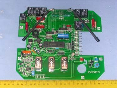
KNF6RX
Mar 26, 2006Remote Control Receiver
Equipment Class
CYY - Communications Receiver used w/Pt 15 Transmitter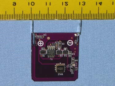
KNF4TX433
Oct 26, 2005AUTOMATED CONTROL
Equipment Class
DSC - Part 15 Security/Remote Control Transmitter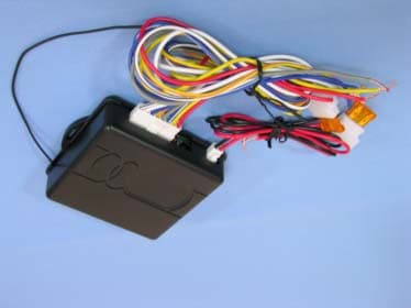
KNFRCU6RX
Sep 26, 2004REMOTE CONTOLLER (RX)
Equipment Class
CXX - Communications Rcvr for use w/ licensed Tx and CBs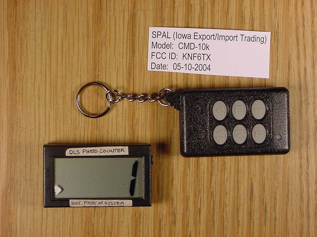
KNF6TX
Jul 05, 2004Automotive Aftermarket Transmitter
Equipment Class
DSC - Part 15 Security/Remote Control Transmitter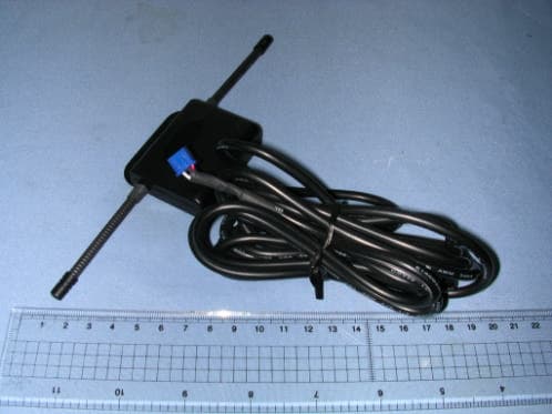
KNFAIRRX
May 09, 2004air kit (rx)
Equipment Class
CRR - Superregenerative Receiver