KNFRCU6RXREMOTE CONTOLLER (RX)
SPAL USA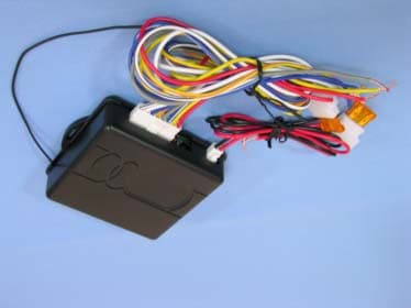
Click to zoom
Application Details
- Equipment Class
- CXX - Communications Rcvr for use w/ licensed Tx and CBs
- Date of Grant
- Sep 26, 2004
- Application Purpose
- Original Equipment
- Date of Application
- Sep 26, 2004
- Equipment Note
- REMOTE CONTOLLER (RX)
- Frequency Range
- 430.00000000 - 436.00000000
- Company
- SPAL USA
- Country
- United States
Documents & Files
Document Text
Text extracted from the exhibit documents filed with the FCC. Open a document above to read the original.
Users Manual
® Installation Manual & Operation Instructions RCU6 Limited Warranty Statement SPAL USA WARRANTY STATEMENT SPAL USA warrants this product to be free from defects in material and workmanship for a period of one (1) year from the date of sale to the original purchaser, and not more than two (2)y ears from the date of manufacture. SPAL USA will repair this product free of charge if, in the judgment of SPAL USA, it has been proven defective within the warranty period. The productshould be returned, at the customer expense, to the location of original purchase. This warrantydoes not cover any expenses incurred in the removal and/or reinstallation of the product.Thisw arranty does not apply to any product damaged by improper installation, accidental misuse, abuse, improper line voltage, fire, flood, lightning, or other acts of God, or a product altered orr epaired by anyone other than SPAL USA.This warranty is in lieu of other warranties, expressed or implied, including any implied warranty of merchantability. No person is authorized to assumefor SPAL USA any other liability concerning the sale of this product. IMPORTANT-KEEP YOUR INVOICE WITH THIS WARRANTY STATEMENT! 07/04 8 Tr ouble Shooting Reverse Polarity Wiring Problems Switch doesn't work properly but the shaved kit transmitters do workStep 1 Did you purchase a switch kit designed for three switches and only use two switches?YES - Connect third switch NO - Check wiring Switch works properly but shaved kit transmitters do not workStep 1 Does the LED on the remote light up when you press the transmitter button?YES - Transmitter works properly continue to step 2 NO - Replace transmitter battery Step 2 Can you hear the receiver make a clicking sound when you press channel 1 or 2 on the transmitter?YES - Receiver and relay work properly. Go to step 4 NO - Go to step 3 Step 3 Does the LED on the receiver light up when the transmitter button is pressed?YES - Transmitter is properly learned and OK, go to Step 4 NO - Check power and ground to the receiver and then reprogram the transmitters Step 4 Use a test light to check for voltage at pin 87 of the relay. Did the test show greater than 10 volts?YES - The relay checked works properly. The other side of the motor is not properly grounded. NO - Connect pin 87 to a proper voltage source. SPAL USA, 512 Tuttle Street, Des Moines, IA 50309-4618 [email protected], www.spal-usa.com Main/Sales: 800-345-0327, Sales: 888-SPAL-USA Te ch Support Line: 800-454-7725 V III I VIIV II YELLOW RED BLUE / WHITE GRAY YELLOW / RED BLUE WHITE WHITE / BLACK FUSE (1) Receiver (2) Remotes (2) Wire Harnesses 2 Installation Instructions for RCU6 This kit is designed to operate six functions via the 6-button remote controls. These channels can be used to operate power door locks, power door releases, trunkr eleases, control linear actuators, or roll up or down power windows. All channels can be Positive or Negative outputs depending on how the input wire is connected. Please refer to the diagrams on page __?_ of this instruction manual for positive, and negative, wiring diagrams and other recommendations, suchas reverse polarity for power windows. **Proper wiring is critical to the correct operation of this product. Make sure all wiresare properly connected, properly grounded, free of potential damage, and are correctlyfused** FUSE Each Kit Contains The Following Components B Y R T T A E Output From Receiver 87A 86 85 30 87 + 12 VDC FUSE 30 87A87 85 86 Output From Receiver Power Window Motor S W I TCH 4 Y T B A T E R 85 86 30 87 Output From Receiver 87A + 12 VDC Output + 12 VDC FUSE Optional Wiring Diagrams Positive Output Negative OutputReverse Polarit y Output T B A T Y E R Output From Receiver 86 Ground Output 30 87A87 85 GROUND FUSE + 12 VDC FOR POWER WINDOWS TWO RELAYS MUST BE PLACED BETWEEN THE SWITCH AND THEWINDOW MOTOR. THE DASHED LINES INDICATE WHERE THE WIRES MUST BE CUT. 5WIRE SWITCH **In a reverse polarity system, a switch that rests at ground must be used.** Positive Output To Device Ground Output To Device V III I VIIV II Negative Output From Receiver Positive Output From Receiver FCC ID INFORMATION FCC ID#: KNF6TX"This device complies with Part 15 of the FCC Rules. Operation is subject to the following twoconditions: (1) This device may not cause harmful interference, and (2) this device must acceptany interference received, including interference that may cause undesired operation."Industry CanadaIC ID#: XXXXXX-6TX (XXXXXX will be replaced with the company number issued by Canada)“The term “IC:” before the radio certification number only signifies that Industry Canada technicalspecifications were met.”Disclaimer StatementCaution: changes or modifications not expressly approved by SPAL USA will void the user'sauthority to operate the equipment. V III I VIIV II Reprogramming the Remote T ransmitters: **This RCU6 can accept up to 4 SPAL remote transmitters (Part # RCU6TX)**The remote transmitters are shipped Pre-Programmed. In the event that a remotetransmitter loses the programmed code, or if you wish to add more remote transmitters, follow these instructions: •Make sure ignition is OFF.• Locate the programming button located on the side of the receiver, next to the LED. •Press the programming button 3 times (The LED will light).•Press Button 1 on each remote you wish to program (The LED will turn off for a moment, then back on with each remote transmitter it recognizes) •The LED will remain lit for approx. 10 seconds after the last remote transmitter has been recognized. •Wait for the LED to go out. Then test each remote transmitter for proper function. To Operate: Press: Channel 1 Button I Channel 2 Button II Channel 3 Button III Channel 4 Button IV Channel 5 Button V Channel 6 Button VI Basic Function of the SP AL Shaved Door Kit The remote control supplied with your kit has four buttons, but is capable of controlling6 channels.Channel 1:Channel 2:Channel 3:Channel 4:Channel 5:Channel 6: Operation Section P…
Text truncated - open the document above for the full version.
Block Diagram
B a nd pa ss F ilte r a nd Antennal Matching N et wor k Radio F r equency Amplif ie r Demodulator L o w Pa ss F ilte r Automa tic Ga in Control MODEL: RCU6 Block Diagram CPU Antenna DRA W N: LINDA CHECKED: LAI APPROVED: LIBER T Y TECHNOLOGY CO., L T D.
External Photos
Spectrum Research & Testing Lab., Inc. No. 101-10, Ling 8, Shan-Tong Li, Chung-Li City, Taoyuan, Taiwan, R.O.C. Photo Page: 1 of 3 PHOTOS OF EUT Spectrum Research & Testing Lab., Inc. No. 101-10, Ling 8, Shan-Tong Li, Chung-Li City, Taoyuan, Taiwan, R.O.C. Photo Page: 2 of 3 PHOTOS OF EUT Spectrum Research & Testing Lab., Inc. No. 101-10, Ling 8, Shan-Tong Li, Chung-Li City, Taoyuan, Taiwan, R.O.C. Photo Page: 3 of 3 PHOTOS OF EUT
ID Label/Location Info
Sample of FCC ID Label THIS DEVICE COMPLIES WITH PART 15 OF THE FCC RULES. OPERATION IS SUBJECT TO THE FOLLOWING TWO CONDITIONS. (1) THIS DEVICE MAY NOT CAUSE HARMFUL INTERFERENCE AND (2) THIS DEVICE MUST ACCEPT ANY INTERFERENCE RECEIVED , INCLUDING INTERFERENCE THAT MAY CAUSE UNDESIRED OPERATION. FCC ID : KNFRCU6RX
Internal Photos
Spectrum Research & Testing Lab., Inc. No. 101-10, Ling 8, Shan-Tong Li, Chung-Li City, Taoyuan, Taiwan, R.O.C. Photo Page: 1 of 4 PHOTOS OF EUT Spectrum Research & Testing Lab., Inc. No. 101-10, Ling 8, Shan-Tong Li, Chung-Li City, Taoyuan, Taiwan, R.O.C. Photo Page: 2 of 4 PHOTOS OF EUT Spectrum Research & Testing Lab., Inc. No. 101-10, Ling 8, Shan-Tong Li, Chung-Li City, Taoyuan, Taiwan, R.O.C. Photo Page: 3 of 4 PHOTOS OF EUT Spectrum Research & Testing Lab., Inc. No. 101-10, Ling 8, Shan-Tong Li, Chung-Li City, Taoyuan, Taiwan, R.O.C. Photo Page: 4 of 4 PHOTOS OF EUT
Test Report
Spectrum Research & Testing Lab., Inc. No. 101-10, Ling 8, Shan-Tong Li, Chung-Li City, Taoyuan, Taiwan, R.O.C. TEST REPORT Reference No.:A04072805 Report No.:FCBA04072805 Page:2 of 15 Date:Aug. 06, 2004 FCC ID:KNFRCU6RX Table of Contents 1. DOCUMENT POLICY AND TEST STATEMENT................................................ 3 1.1 DOCUMENT POLICY ........................................................................................ 3 1.2 TEST STATEMENT............................................................................................ 3 1.3 EUT MODIFICATION ......................................................................................... 3 2. DESCRIPTION OF EUT AND TEST MODE ...................................................... 4 2.1 GENERAL DESCRIPTION OF EUT .................................................................. 4 2.2 DESCRIPTION OF EUT INTERNAL DEVICE.................................................... 4 2.3 DESCRIPTION OF TEST MODE ....................................................................... 4 2.4 DESCRIPTION OF SUPPORT UNIT ................................................................. 5 3. DESCRIPTION OF APPLIED STANDARDS ...................................................... 5 4. CONDUCTED EMISSION TEST ........................................................................ 6 4.1 CONDUCTED EMISSION LIMIT........................................................................ 6 4.2 TEST EQUIPMENT............................................................................................ 6 4.3 TEST SETUP..................................................................................................... 7 4.4 TEST PROCEDURE .......................................................................................... 7 4.5 EUT OPERATING CONDITION ......................................................................... 7 4.6 TEST RESULT ................................................................................................... 8 5. RADIATED EMISSION TEST ............................................................................. 9 5.1 RADIATED EMISSION LIMIT............................................................................. 9 5.2 TEST EQUIPMENT............................................................................................ 9 5.3 TEST SET-UP...................................................................................................10 5.4 TEST PROCEDURE .........................................................................................11 5.5 EUT OPERATING CONDITION ........................................................................11 5.6 RADIATED EMISSION TEST RESULT.............................................................12 6. PHOTOS OF TESTING.................................................................................... 13 7. TERMS OF ABRIVATION................................................................................. 15 Spectrum Research & Testing Lab., Inc. No. 101-10, Ling 8, Shan-Tong Li, Chung-Li City, Taoyuan, Taiwan, R.O.C. TEST REPORT Reference No.:A04072805 Report No.:FCBA04072805 Page:3 of 15 Date:Aug. 06, 2004 FCC ID:KNFRCU6RX 1. DOCUMENT POLICY AND TEST STATEMENT 1.1 DOCUMENT POLICY - The report shall not be reproduced except in full, without the written approval of SRT Lab, Inc. - The report must not be used by the applicant to claim that the product is endorsed by NVLAP, TÜV, NEMKO and SRT.. - The NVLAP logo applies only to the applicable standards specified in this report. 1.2 TEST STATEMENT - The test results in the report apply only to the unit tested by SRT Lab. - There was no deviation from the requirements of test standards during the test. - AC power source, 120 Vac/60 Hz, was used during the test. 1.3 EUT MODIFICATION - No modification in SRT Lab. Spectrum Research & Testing Lab., Inc. No. 101-10, Ling 8, Shan-Tong Li, Chung-Li City, Taoyuan, Taiwan, R.O.C. TEST REPORT Reference No.:A04072805 Report No.:FCBA04072805 Page:4 of 15 Date:Aug. 06, 2004 FCC ID:KNFRCU6RX 2. DESCRIPTION OF EUT AND TEST MODE 2.1 GENERAL DESCRIPTION OF EUT PRODUCT RCU6 MODEL NO. RCU6 POWER SUPPLY DC 5V CABLE 0.6m shielded cable NOTE : The EUT is the receiver part of a remote controller. For more detailed information, please refer to the specifications or User’s manual provided by manufacturer. 2.2 DESCRIPTION OF EUT INTERNAL DEVICE DEVICE BRAND / MAKER MODEL # FCC ID/DOC REMARK N/A NOTE : 1. Frequency range to be measured. Radiated emission is 30MHz to 1GHz. 2.3 DESCRIPTION OF TEST MODE N/A (It is only applicable to more than one test mode.) Spectrum Research & Testing Lab., Inc. No. 101-10, Ling 8, Shan-Tong Li, Chung-Li City, Taoyuan, Taiwan, R.O.C. TEST REPORT Reference No.:A04072805 Report No.:FCBA04072805 Page:5 of 15 Date:Aug. 06, 2004 FCC ID:KNFRCU6RX 2.4 DESCRIPTION OF SUPPORT UNIT The EUT was configured by the requirement of ANSI C63.4:2003 and CISRP22:2003. All interface ports were connected to the appropriate support units via specific cables. The support units and cables are listed below. NO DEVICE BRAND MODEL # FCC ID/DOC CABLE 1 FAN N/A N/A N/A N/A 2 FAN N/A N/A N/A N/A 3 4 5 NOTE : For the actual test configuration, please refer to the photos of testing. 3. DESCRIPTION OF APPLIED STANDARDS The EUT is a kind of ITE and according to the specifications provided by the applicant, it must comply with the requirements of the following standards: 47 CFR Part 15 Subpart B, Class B All tests have been performed and recorded as per the above standards. Spectrum Research & Testing Lab., Inc. No. 101-10, Ling 8, Shan-Tong Li, Chung-Li City, Taoyuan, Taiwan, R.O.C. TEST REPORT Reference No.:A04072805 Report No.:FCBA04072805 Page:6 of 15 Date:Aug. 06, 2004 FCC ID:KNFRCU6RX 4. CONDUCTED EMISSION TEST 4.1 CONDUCTED EMISSION LIMIT Class A (dBμV) Class B (dBμV) FREQUENCY (MHz) Quasi-peak Average Quasi-peak Average 0.15 - 0.5 79 66 66 - 56 56 - 46 0.5 - 5.0 73 60 56 46 5.0 - 30.0 73 60 …
Text truncated - open the document above for the full version.
Test Setup Photos
PHOTOS OF TESTING - Conducted test - Radiated test
Contact Information
Applicant
Dan McNeal(QC/Engineering Manager)
Test Firm
Spectrum Research & Testing Lab.Linda Chiang
Technical Specifications
| # | Rule Parts | Frequency Range | Power Output |
|---|---|---|---|
| 1 | 15B | 430 MHz - 436 MHz | - |
Other Applications from SPAL USA
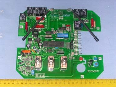
KNF6RX
Mar 26, 2006Remote Control Receiver
Equipment Class
CYY - Communications Receiver used w/Pt 15 Transmitter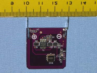
KNF4TX433
Oct 26, 2005AUTOMATED CONTROL
Equipment Class
DSC - Part 15 Security/Remote Control Transmitter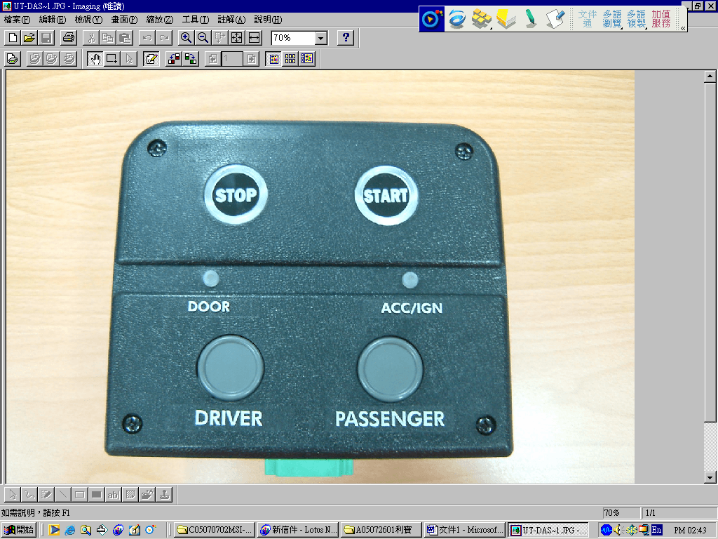
KNFUTRX
Sep 28, 2005Automated Control
Equipment Class
DXX - Part 15 Low Power Communication Device Transmitter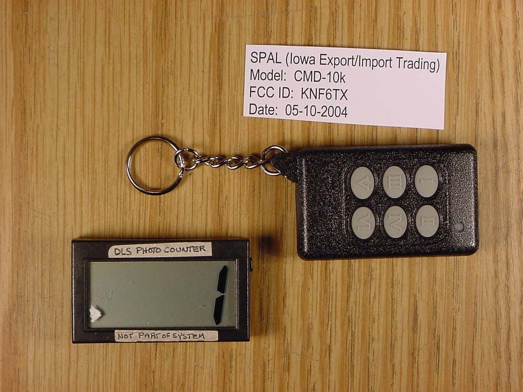
KNF6TX
Jul 05, 2004Automotive Aftermarket Transmitter
Equipment Class
DSC - Part 15 Security/Remote Control Transmitter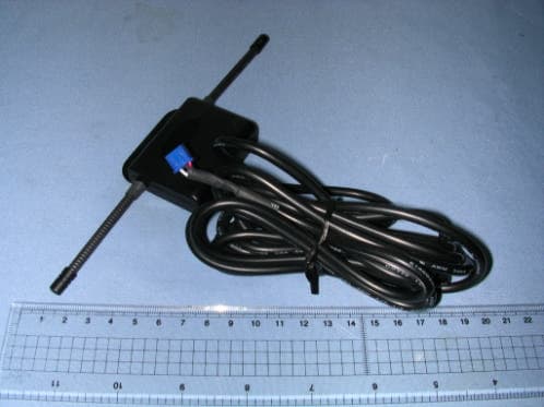
KNFAIRRX
May 09, 2004air kit (rx)
Equipment Class
CRR - Superregenerative Receiver