KNY-121819DEE521435-470MHz, 2 W, Licensed Radio System Module
FreeWave Technologies Inc.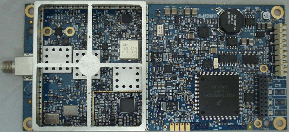
Click to zoom
Application Details
- Equipment Class
- TNB - Licensed Non-Broadcast Station Transmitter
- Date of Grant
- Aug 10, 2011
- Application Purpose
- Original Equipment
- Date of Application
- Aug 10, 2011
- Equipment Note
- 435-470MHz, 2 W, Licensed Radio System Module
- Frequency Range
- 435.00000000 - 470.00000000
- Company
- FreeWave Technologies Inc.
- Country
- United States
Documents & Files
Document Text
Text extracted from the exhibit documents filed with the FCC. Open a document above to read the original.
Users Manual
LRS -455- EU Data Transceiver Manual LUM 0032AA Rev A Version 1.0 i FreeWave Technologies LRS-455-EU Data Transceiver Version 1.0, Revision A FreeWave Technologies, Inc. 1880 South Flatiron Court Boulder, CO 80301 (303) 381 -9200 (303) 786-9948 Fax www.FreeWave.com LRS -455- EU Data Transceiver Users Manual LUM 0032AA Rev A Version 1.0 ii LICENSED BAND WIRELESS DATA TRANSCEIVER USER MANUAL Copyright © 1995-2011 by FreeWave Technologies, Inc. All rights reserved. Published 2011. W ARRANTY FreeWave Technologies warrants your FreeWave® Wireless Data Transceiver against defects in materials and manufacturing for a period of two years from the date of shipment. In the event of a Product failure due to materials or workmanship, FreeWave will, at its option, repair or replace the Product. The Product must be returned to FreeWave upon receiving a Return Material Authorization (RMA) for evaluation of Warranty Coverage. In no event will FreeWave Technologies Inc., its suppliers, and its licensors be liable for any damages arising from the use of or inability to use this Product. This includes business interruption, loss of business information, or other loss which may arise from the use of this Product. Please be advised that OEM customer’s warranty periods may vary. Warranty Policy may not apply: 1. If Product repair, adjustments or parts replacements is required due to accident, neglect, unusual physical, electrical or electromagnetic stress. 2. If Product is used outside of FreeWave specifications. 3. If Product has been modified, repaired or altered by Customer unless FreeWave specifically authorized such alterations in each instance in writing. This includes the addition of conformal coating. Special Rate Replacement Option A special rate replacement option is offered to non-warranty returns or upgrades. The option to purchase the replacement unit at this special rate is only valid for that RMA. The special replacement rate option expires if not exercised within 30 days of final disposition of RMA. R ESTRICTED RIGHTS Any product names mentioned in this manual may be trademarks or registered trademarks of their respective companies and are hereby acknowledged. Information in this manual is subject to change without notice and is proprietary and confidential to FreeWave Technologies, Inc. This manual is for use by purchasers and other authorized users of the FreeWave® Wireless Data Transceiver only. No part of this manual may be reproduced or transmitted in any form or by any means, electronic or mechanical, or for any purpose without the express written permission of FreeWave Technologies, Inc. FreeWave’s Wireless Data Transceivers are designed and manufactured in the United States of America. Printed in the United States of America. LRS -455- EU Data Transceiver Users Manual LUM 0032AA Rev A Version 1.0 iii UL NOTIFICATION Models LRS-455-EU-C, LRS-455 -EU-C-MS, LRS-455-EU-CE, and LRS-455-EU-CW are suitable for use in non- hazardous locations only. Input voltage for the above models is 6 to 30 volts DC. WARNING: DO NOT REMOVE OR INSERT DIAGNOSTICS CABLE WHILE CIRCUIT IS LIVE UNLESS THE AREA IS KNOWN TO BE FREE OF IGNITION CONCENTRATIONS OF FLAMMABLE GASES OR VAPORS. FCC NOTIFICATIONS This device complies with part 15 of the FCC rules. Operation is subject to the following two conditions: 1) This device may not cause harmful interference and 2) this device must accept any interference received, including interference that may cause undesired operation. This device must be operated as supplied by FreeWave Technologies, Inc. Any changes or modifications made to the device without the express written approval of FreeWave Technologies may void the user's authority to operate the device. CAUTION: The LRS -455-EU transceivers have a maximum transmitted output power of 2W. It is recommended that the transmit antenna be kept at least 18.3 cm away from nearby persons to satisfy FCC RF exposure requirements. This equipment has been tested and found to comply with the limits for a Class B digital device, pursuant to part 15 of the FCC Rules. These limits are designed to provide reasonable protection against harmful interference in a residential installation. This equipment generates, uses, and can radiate radio frequency energy and, if not installed and used in accordance with the instructions, may cause harmful interference to radio communications. However, no guarantee shall be made that interference will not occur in a particular installation. If this equipment does cause harmful interference to radio or television reception, which can be determined by turning the equipment off and on, the user is encouraged to try to correct the interference by one or more of the following measures: • Reorient or relocate the receiving antenna. • Incr ease the separation between the equipment and receiver. • Connect the equipment into an outlet on a circuit different from that to which the receiver is connected. • Consult the dealer or an experienced radio/TV technician for help. Note: Whenever any FreeWave Technologies module is placed inside an enclosure a label must be placed on the outside of that enclosure which includes the module's FCC ID. IC N OTIFICATIONS This device complies with Industry Canada licence-exempt RSS standard(s). Operation is subject to the following two conditions: (1) this device may not cause interference, and (2) this device must accept any interference, including interference that may cause undesired operation of the device. Ce dispositif est conforme aux normes permis-exemptes du Canada RSS d'industrie. L'opération est sujette aux deux conditions suivantes : (1) ce dispositif peut ne pas causer l'interférence, et (2) ce dispositif doit accepter n'importe quelle interférence, y compris l'interférence qui peut causer le fonctionnement peu désiré du dispositif. Note: The LRS-455- EU transceivers are approved for use in Canada within the 450MHz to 470MHz band. LRS -455- EU Data Transceiver Us…
Text truncated - open the document above for the full version.
Cover Letter(s)
June 30, 2011 To: Elite Electronic Engineering, Inc. 1516 Centre Circle Downers Grove, IL 60515 From: FreeWave Technologies, Inc. 1880 S Flatiron Ct. Suite F Boulder, CO 80301 FCC ID: KNY-121819dee521 Request for Confidentiality In accordance with 47 C.F.R. Section 0.459, we, FreeWave Technologies Inc., hereby request confidentiality for the block diagram, schematic, bill of materials, theory of operation, product description and setup document presented for certification. In support of the Request for Confidentiality, the following is stated: Enclosed within this application is technical information which we deem to be trade secrets and proprietary. If made public, the information might be used to our disadvantage. To assist in assuring that we receive the full value of our product and protect its competitive posture, we respectfully request this grant of confidentiality. Thank you. Regards, Rich Arment Regulatory Compliance Leader FreeWave Technologies Inc. COMMUNICATION WITHOUT BARRIERS 1880 South Flatiron Court Suite F Boulder Colorado 80301 303.381.9200 www.freewave.com
Cover Letter(s)
August 23, 2011 Attn: Director of Certification Re: FCC ID: KNY-121819dee521 Request Modular Authority We (FreeWave Technologies Inc.) hereby request Modular Approval based on the numbered requirements identified below as we address them to be included in our application for equipment authorization. 1. The modular transmitter must have its own RF shielding. This is intended to ensure that the module does not have to rely upon the shielding provided by the device into which it is installed in order for all modular transmitter emissions to comply with Part 15 limits. It is also intended to prevent coupling between the RF circuitry of the module and any wires or circuits in the device into which the module is installed. Such coupling may result in non-compliant operation. Our equipment provides RF shield over the whole RF/analog section as well as additional shield over RF VCO area. 2. The modular transmitter must have buffered modulation/data inputs (if such inputs are provided) to ensure that the module will comply with Part 15 requirements under conditions of excessive data rates or over-modulation. Our equipment buffers the data inputs using RS-232 or RS-485/422 (selectable) integrated circuits before sending the data to the Microcontroller. The Microcontroller independently sets over the air data rates and TX deviation 3. The modular transmitter must have its own power supply regulation. This is intended to ensure that the module will comply with Part 15 requirements regardless of the design of the power supplying circuitry in the device into which the module is installed. Our equipment meets this by providing on-board switching regulator that assures constant output voltage within specified Vin variation (7V-27V ±10%) 4. The modular transmitter must comply with the antenna requirements of Section 15.203 and 15.204(c). The antenna must either be permanently attached or employ a “unique” antenna coupler (at all connections between the module and the antenna, including the cable). Any antenna used with the module must be approved with the module, either at the time of initial authorization or through a Class II permissive change. The “professional installation” provision of Section 15.203 may not be applied to modules. Our equipment meets this by providing an SMA or MCX or TNC connector and requiring professional installation. 5. The modular transmitter must be tested in a stand-alone configuration, i.e., the module must not be inside another device during testing. This is intended to demonstrate that the module is capable of complying with Part 15 emission limits regardless of the device into which it is eventually installed. Unless the transmitter module will be battery powered, it must comply with the AC line conducted requirements found in Section 15.207. AC or DC power lines and data input/output lines connected to the module must not contain ferrites, unless they will be marketed with the module (see Section 15.27(a)). The length of these lines shall be length typical of actual use or, if that length is unknown, at least 10 centimeters to insure that there is no coupling between the case of the module and supporting equipment. Any accessories, peripherals, or support equipment connected to the module during testing shall be unmodified or commercially available (see Section 15.31(i)). Our equipment was tested in stand-alone mode with external supply connected to radio module. 6. The modular transmitter must be labeled with its own FCC ID number, and, if the FCC ID is not visible when the module is installed inside another device, then the outside of the device into which the module is installed must also display a label referring to the enclosed module. This exterior label can use wording such as the following: “Contains Transmitter Module FCC ID: XYZMODEL1” or “Contains FCC ID: XYZMODEL1.” Any similar wording that expresses the same meaning may be used. The Grantee may either provide such a label, an example of which must be included in the application for equipment authorization, or, must provide adequate instructions along with the module which explain this requirement. In the latter case, a copy of these instructions must be included in the application for equipment authorization. Our equipment meets this by providing label with FCC ID clearly visible on every unit. 7. The modular transmitter must comply with any specific rule or operating requirements applicable to the transmitter and the manufacturer must provide adequate instructions along with the module to explain any such requirements. A copy of these instructions must be included in the application for equipment authorization. For example, there are very strict operational and timing requirements that must be met before a transmitter is authorized for operation under Section 15.231. For instance, data transmission is prohibited, except for operation under Section 15.231(e), in which case there are separate field strength level and timing requirements. Compliance with these requirements must be assured. Our equipment meets this by limiting operating frequency and Output RF power by internal FW setting. We also provide operating manuals in printed form and on soft media. 8. The modular transmitter must comply with any applicable RF exposure requirements. For example, FCC Rules in Sections 2.1091, 2.1093 and specific Sections of Part 15, including 15.319(i), 15.407(f), 15.253(f) and 15.255(g), require that Unlicensed PCS, UNII and millimeter wave devices perform routine environmental evaluation for RF Exposure to demonstrate compliance. In addition, spread spectrum transmitters operating under Section 15.247 are required to address RF Exposure compliance in accordance with Section 15.247(b)(4). Modular transmitters approved under other Sections of Part 15, when necessary, may also need to address certain RF Exposure concerns, typically by providing specific installation and operating instructions for users, installers and ot…
Text truncated - open the document above for the full version.
External Photos
LSR455-EU-C, Label LSR455-EU-C, Bottom LSR455-EU-C, Top No Shield LSR455-EU-C, Top w/ Shield ---------- LRS455-EU-C-MS is identical assembly except the RF connector is MCX instead of SMA. ---------- LSR455-EU-CE, Label LRS455-EU-C Top (Enclosure) LRS455-EU-C Front (Enclosure) LRS455-EU-C Bottom (Enclosure) LRS455-EU-C Top board stack (Enclosure) LRS455-EU-C Side 1 board stack (Enclosure) LRS455-EU-C Side 2 board stack (Enclosure) LRS455-EU-C Bottom board stack (Enclosure) ---------- LRS455-EU-CW will be a waterproof version of the LRS455-EU-CE. The front panel will change to accommodate waterproof connectors; however, this has not yet been designed.
ID Label/Location Info
LSR455-EU-C, Label LSR455-EU-C, Bottom LSR455-EU-C, Top No Shield LSR455-EU-C, Top w/ Shield ---------- LRS455-EU-C-MS is identical assembly except the RF connector is MCX instead of SMA. ---------- LSR455-EU-CE, Label LRS455-EU-C Top (Enclosure) LRS455-EU-C Front (Enclosure) LRS455-EU-C Bottom (Enclosure) LRS455-EU-C Top board stack (Enclosure) LRS455-EU-C Side 1 board stack (Enclosure) LRS455-EU-C Side 2 board stack (Enclosure) LRS455-EU-C Bottom board stack (Enclosure) ---------- LRS455-EU-CW will be a waterproof version of the LRS455-EU-CE. The front panel will change to accommodate waterproof connectors; however, this has not yet been designed.
Internal Photos
LSR455-EU-C, Label LSR455-EU-C, Bottom LSR455-EU-C, Top No Shield LSR455-EU-C, Top w/ Shield ---------- LRS455-EU-C-MS is identical assembly except the RF connector is MCX instead of SMA. ---------- LSR455-EU-CE, Label LRS455-EU-C Top (Enclosure) LRS455-EU-C Front (Enclosure) LRS455-EU-C Bottom (Enclosure) LRS455-EU-C Top board stack (Enclosure) LRS455-EU-C Side 1 board stack (Enclosure) LRS455-EU-C Side 2 board stack (Enclosure) LRS455-EU-C Bottom board stack (Enclosure) ---------- LRS455-EU-CW will be a waterproof version of the LRS455-EU-CE. The front panel will change to accommodate waterproof connectors; however, this has not yet been designed.
RF Exposure Info
August 10, 2011 Maximum Permissible Exposure calculations To whom it may concern, The subject of this document is the Maximum Permissible Exposure (MPE) calculation for the FreeWave Technologies 435-470MHz Licensed Band transceiver. The MPE distance is calculated for the worst-case of a 100% transmitter duty cycle. For an isotropic radiator the surface area of a sphere can be used to determine the area over which the transceiver energy is radiated. Surface area of a sphere = 4 * π * radius 2 In the case where there is an antenna gain, the worst-case energy density is increased by the antenna gain. In this case, the exposure level for a controlled environment can be calculated as follows: MPE distance = ((output power*duty cycle*10*(antenna gain/10)) / (4* π*Exposure Limit [mW/cm 2 ])) 1/2 In the case of 7 dBi antenna MPE distance = ((2000 mW * 1 * 5.01) /( 4 * 3.14 * 1.5)) 1/2 = 18.3 cm Sincerely, Rich Arment Engineer COMMUNICATION WITHOUT BARRIERS FREEWAVE TECHNOLOGIES SPREAD SPECTRUM RADIOS 1880 South Flatiron Court Suite F Boulder Colorado 80301 303.381.9200 www.freewave.com
Test Report
Engineering Test Report No. 1101611-01 Measurement of RF Emissions from an LRS455-EU-C-MS Transceiver For FreeWave Technologies, Inc. 1800 S. Flatiron Crt. Boulder, CO 80301 P.O. Number 35038 Date Tested July 14, 2011 through July 22, 2011 Test Personnel Daniel Crowder Test Specification FCC "Code of Federal Regulations” Title 47 Part 15, Subpart B and Part 90, Subpart I RSS-119 Issue 11 June 2011 Test Report By: Daniel Crowder EMC Engineer Approved By: Raymond J. Klouda Registered Professional Engineer of Illinois - 44894 Elite Electronic Engineering, Inc. 1516 Centre Circle Downers Grove, IL 60515 Tel : (630) 495-9770 Fax: (630) 495-9785 www.elitetest.com Engineering Test Report No. 1101611-01 TABLE OF CONTENTS PARAGRAPH DESCRIPTION OF CONTENTS PAGE NO. THIS REPORT SHALL NOT BE REPRODUCED, EXCEPT IN FULL, WITHOUT THE WRITTEN APPROVAL OF ELITE ELECTRONIC ENGINEERING INCORPORATED. Page 2 of 69 1. Introduction ................................................................................................................................................... 5 1.1. Scope of Tests ..................................................................................................................................... 5 1.2. Purpose ............................................................................................................................................... 5 1.3. Deviations, Additions and Exclusions .................................................................................................. 5 1.4. EMC Laboratory Identification ............................................................................................................. 5 1.5. Laboratory Conditions.......................................................................................................................... 5 2. Applicable Documents .................................................................................................................................. 5 3. EUT Setup and Operation ............................................................................................................................ 6 3.1. General Description ............................................................................................................................. 6 3.1.1. Power Input ................................................................................................................................. 6 3.1.2. Peripheral Equipment ................................................................................................................. 6 3.1.3. Signal Input/Output Leads .......................................................................................................... 6 3.1.4. Grounding ................................................................................................................................... 6 3.2. Operational Mode ................................................................................................................................ 6 3.3. EUT Modifications ................................................................................................................................ 6 4. Test Facility and Test Instrumentation ......................................................................................................... 6 4.1. Shielded Enclosure .............................................................................................................................. 6 4.2. Test Instrumentation ............................................................................................................................ 6 4.3. Calibration Traceability ........................................................................................................................ 6 4.4. Measurement Uncertainty ................................................................................................................... 6 5. Test Procedures ........................................................................................................................................... 7 5.1. Receiver ............................................................................................................................................... 7 5.1.1. Power line Conducted Emission Measurements ........................................................................ 7 5.1.1.1. Requirement................................................................................................................................ 7 5.1.2. Antenna Conducted Emission Measurements ............................................................................ 7 5.1.2.1. Requirements .............................................................................................................................. 7 5.1.2.2. Procedures .................................................................................................................................. 7 5.1.2.3. Results ........................................................................................................................................ 7 5.1.3. Radiated Measurements ............................................................................................................. 7 5.1.3.1. Requirements .............................................................................................................................. 7 5.1.3.2. Procedures .................................................................................................................................. 8 5.1.3.3. Results ........................................................................................................................................ 8 5.2. Transmitter ........................................................................................................................................... 8 5.2.1. RF Power Output ..........................................................................................…
Text truncated - open the document above for the full version.
Test Setup Photos
Engineering Test Report No. 1101611-01 Page 17 of 69 Figure 2 Test Setup for Radiated Emissions, 30MHz to 1GHz – Horizontal Polarization Test Setup for Radiated Emissions, 30MHz to 1GHz – Vertical Polarization Engineering Test Report No. 1101611-01 Page 18 of 69 Figure 3 Test Setup for Radiated Emissions, Above 1GHz – Horizontal Polarization Test Setup for Radiated Emissions, Above 1GHz – Vertical Polarization Engineering Test Report No. 1101611-01 Page 19 of 69 Figure 4 Test Setup for Frequency Stability Test Setup for Frequency Stability Engineering Test Report No. 1101611-01 Page 20 of 69 Figure 5 Test Setup for Transient Frequency Behavior
Contact Information
Applicant
Richard Reisbick(VP Engineering)
Technical Specifications
| # | Rule Parts | Frequency Range | Power Output | Emission | Tolerance |
|---|---|---|---|---|---|
| 1 | 90 | 435 MHz - 470 MHz | 2 W | 9K68F1D | 2.5000000000 ppm |
Other Applications from FreeWave Technologies Inc.
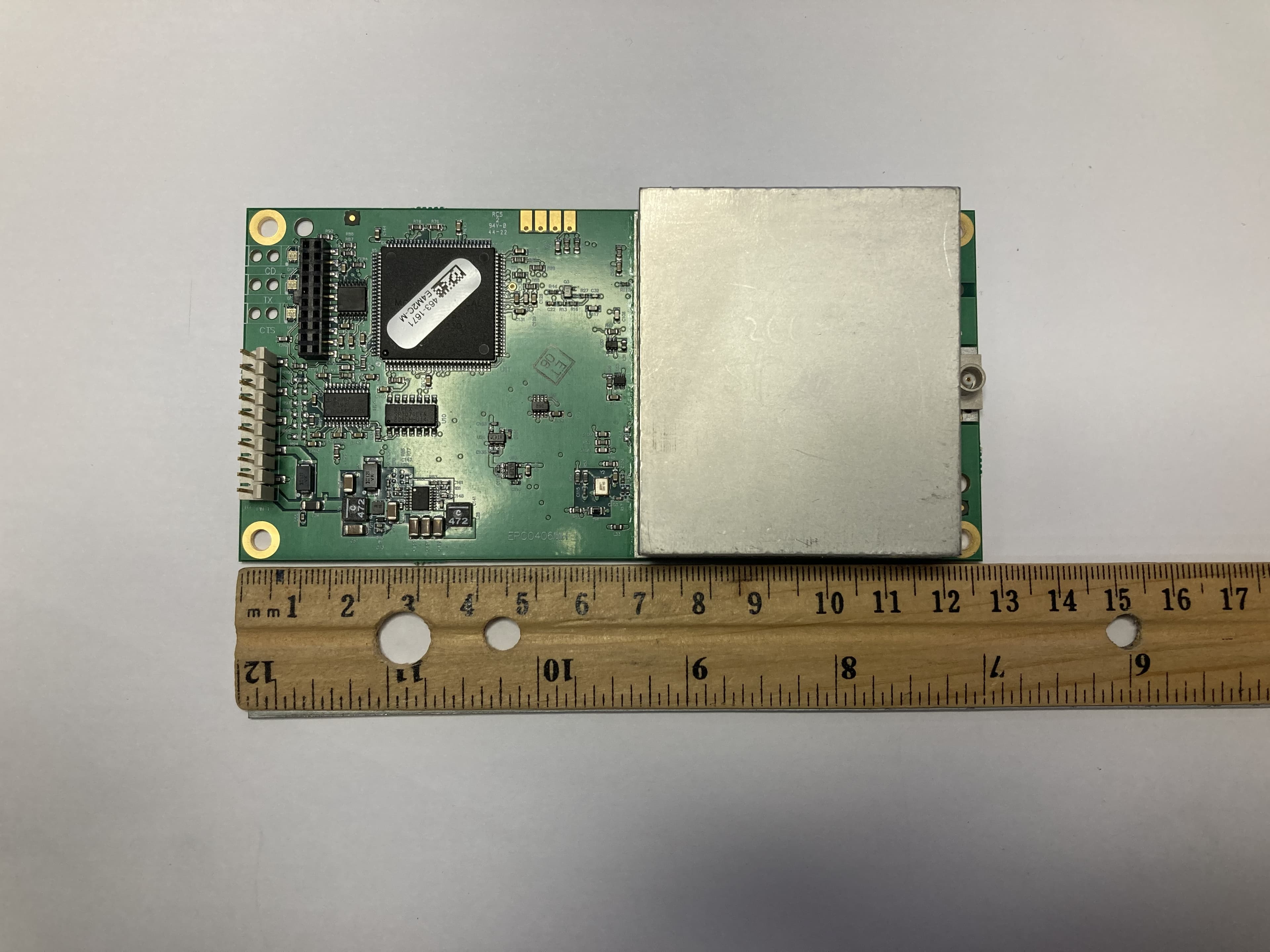
KNYLRS455C
Oct 01, 2023LR455C
Equipment Class
TNB - Licensed Non-Broadcast Station Transmitter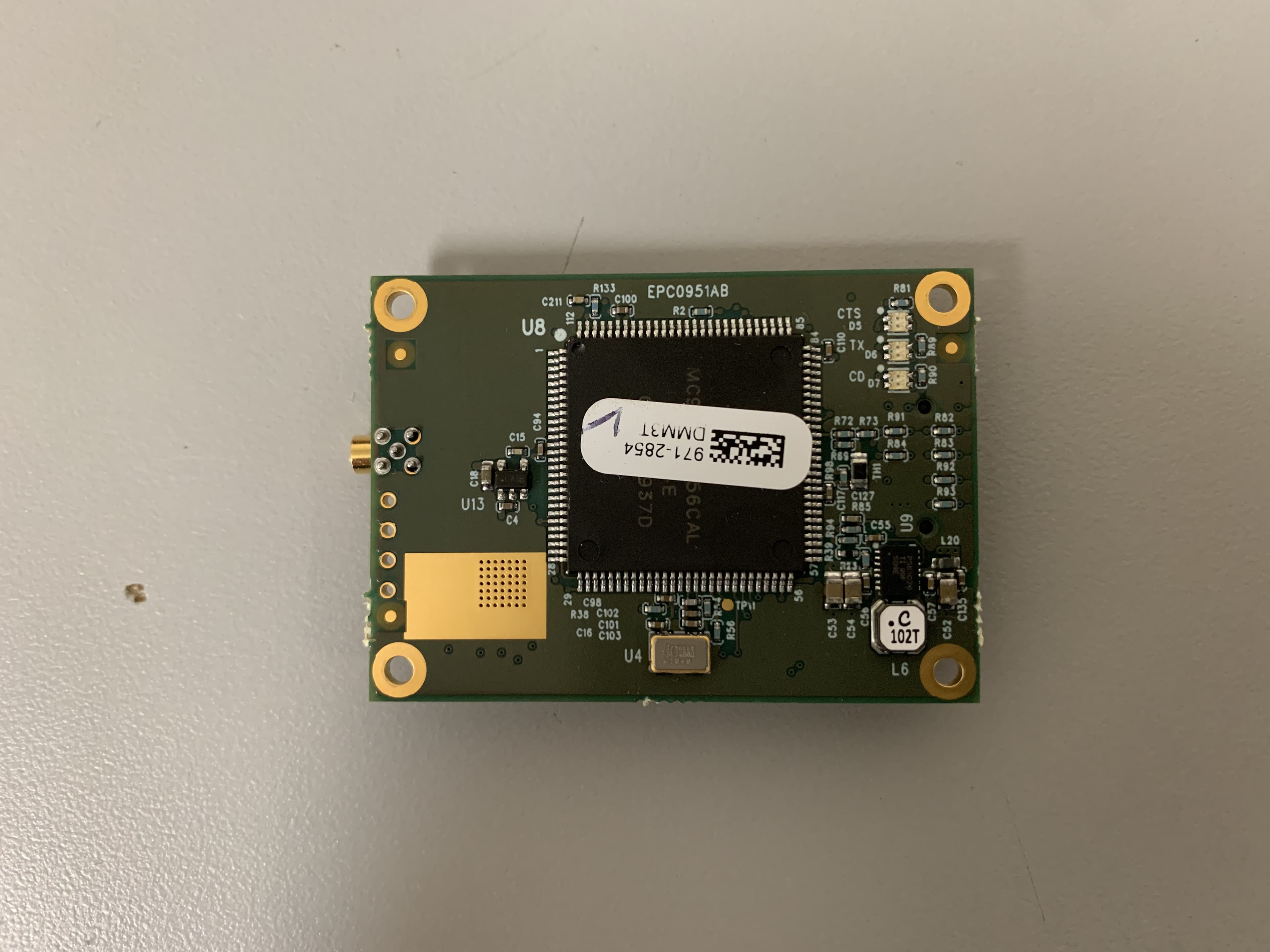
KNYMM3
Aug 25, 2020FHSS 902 - 928 MHz ISM band radio
Equipment Class
DSS - Part 15 Spread Spectrum Transmitter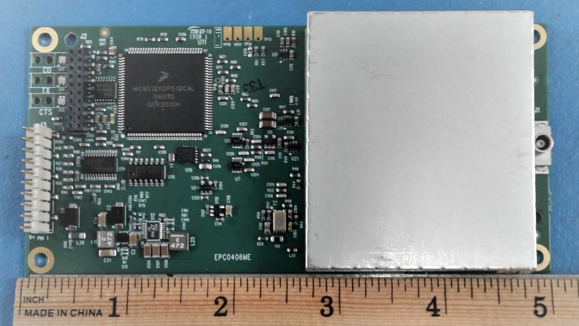
KNYLRS455A
Aug 04, 2020435-470 MHz Licensed Band Transceiver,
Equipment Class
TNB - Licensed Non-Broadcast Station Transmitter
KNYPRW5000AA
Oct 22, 2015Wireless 802.11ac/b/g/n access point
Equipment Class
DTS - Digital Transmission System
KNYAMM0921TT
Jan 14, 2014MM2
Equipment Class
DSS - Part 15 Spread Spectrum Transmitter