KNYAMM0921TTMM2
FreeWave Technologies Inc.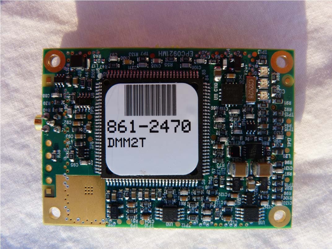
Click to zoom
Application Details
- Equipment Class
- DSS - Part 15 Spread Spectrum Transmitter
- Date of Grant
- Jan 14, 2014
- Application Purpose
- Original Equipment
- Date of Application
- Jan 14, 2014
- Equipment Note
- MM2
- Frequency Range
- 902.25000000 - 927.82000000
- Company
- FreeWave Technologies Inc.
- Country
- United States
Documents & Files
Document Text
Text extracted from the exhibit documents filed with the FCC. Open a document above to read the original.
Users Manual
PartNumber:LIM0001AA Revision:E LastUpdated:01/08/2014 MM2WirelessDataTransceivers MM2-T MM2-LV-T MM2-MR-R MM2-MR-T IntegrationGuide SafetyInformation Warning!Donotremoveorinsertdiagnosticscablewhilecircuitislive. Miseengarde!Nepasenleverouinsérerlecâbledediagnosticalorsquelecircuitest soustension.. Warranty FreeWaveTechnologies,Inc.warrantsyourFreeWave®WirelessDataTransceiveragainstdefectsinmaterialsand manufacturingforaperiodoftwoyearsfromthedateofshipment,dependingonmodelnumber.Intheeventofa Productfailureduetomaterialsorworkmanship,FreeWavewill,atitsdiscretion,repairorreplacetheProduct.For evaluationofWarrantycoverage,returntheProducttoFreeWaveuponreceivingaReturnMaterialAuthorization (RMA). InnoeventwillFreeWaveTechnologies,Inc.,itssuppliers,oritslicensorsbeliableforanydamagesarisingfrom theuseoforinabilitytousethisProduct.Thisincludesbusinessinterruption,lossofbusinessinformation,orother losswhichmayarisefromtheuseofthisProduct.OEMcustomer’swarrantyperiodscanvary. WarrantyPolicywillnotapplyinthefollowingcircumstances: 1.IfProductrepair,adjustments,orpartsreplacementsarerequiredduetoaccident,neglect,orundue physical,electrical,orelectromagneticstress. 2.IfProductisusedoutsideofFreeWavespecificationsasstatedintheProduct'sdatasheet. 3.IfProducthasbeenmodified,repaired,oralteredbyCustomerunlessFreeWavespecificallyauthorized suchalterationsineachinstanceinwriting.Thisincludestheadditionofconformalcoating. SpecialRateReplacementOption Aspecialratereplacementoptionisofferedtonon-warrantyreturnsorupgrades.Theoptiontopurchasethe replacementunitatthisspecialrateisonlyvalidforthatRMA.Thespecialreplacementrateoptionexpiresifnot exercisedwithin30daysoffinaldispositionofRMA. RestrictedRights Anyproductnamesmentionedinthismanualmaybetrademarksorregisteredtrademarksoftheirrespective companiesandareherebyacknowledged. ThismanualisforusebypurchasersandotherauthorizedusersofFreeWaveproducts. Nopartofthismanualmaybereproducedortransmittedinanyformorbyanymeans,electronicormechanical,or foranypurposewithouttheexpresswrittenpermissionofFreeWaveTechnologies,Inc.FreeWavereservesthe righttomakechangestothismanualwithoutnotice.FreeWaveassumesnoresponsibilityorliabilityfortheuseof thismanualortheinfringementofanycopyrightorotherproprietaryright. FreeWaveproductsaredesignedandmanufacturedintheUnitedStatesofAmerica. FreeWaveTechnologies,Inc. Boulder,CO 303.381.9200 TollFree:1.866.923.6168 PrintedintheUnitedStatesofAmerica.Fax:303.786.9948 Copyright©2013byFreeWaveTechnologies,Inc.Allrightsreserved.www.FreeWave.com LIM0001AARevEii FreeWaveTechnologies,Inc.productsmaybesubjecttocontrolbytheExportAdministrationRegulations (EAR)and/ortheInternationalTrafficinArmsRegulations(ITAR).Export,re-export,ortransferofthese productswithoutrequiredauthorizationfromtheU.S.DepartmentofCommerce,BureauofIndustryand Security,ortheU.S.DepartmentofState,DirectorateofDefenseTradeControls,asapplicable,isprohibited. Anypartyexporting,re-exporting,ortransferringFreeWaveproductsisresponsibleforobtainingall necessaryU.S.governmentauthorizationsrequiredtoensurecompliancewiththeseandotherapplicable U.S.laws.Consultwithyourlegalcounselforfurtherguidance. ULNotifications ModelsMM2-T-U,MM2-LV-T-U,MM2-MR-R-U,andMM2-MR-T-UaresuitableforuseinClass1,Division2, GroupsA,B,C,andDornon-hazardouslocationsonly.Donotconnectordisconnectanyconnectorswhilethe circuitisliveunlesstheareaisknowntobenon-hazardous. Warning!EXPLOSIONHAZARD-SUBSTITUTIONOFCOMPONENTSMAYIMPAIR SUITABILITYFORCLASS1,DIVISION2. Miseengarde!RISQUED'EXPLOSION-LASUBSTITUTIONDECOMPOSANTSPEUT ALTÉRERLESQUALITÉSPOURLACLASSE1,DIVISION2. Warning!DONOTREMOVEORINSERTTHEDIAGNOSTICSCABLEWHILETHE CIRCUITISLIVE. Miseengarde!Nepasenleverouinsérerlecâbledediagnosticalorsquelecircuitest soustension. InputvoltagefortheMM2-T-Umodelsis+5.0VDC.InputvoltagefortheMM2-LV-T-Umodelsis+3.5VDC(±5%). InputvoltagefortheMM2-MR-R-UandMM2-MR-T-Umodelsis+6.5VDCto+30.0VDC. Important:InputpowershallbederivedfromasingleClass2powersource. FCCNotifications Thisdevicecomplieswithpart15oftheFCCrules.Operationissubjecttothefollowingtwoconditions:1)This devicemaynotcauseharmfulinterferenceand2)thisdevicemustacceptanyinterferencereceived,including interferencethatmaycauseundesiredoperation. ThisinstallationguidecoversallmodelsoftheFreeWaveTechnologies900MHzspreadspectrumtransceiversold underFCCIDKNYAMM0921TT. AllmodelssoldundertheFCCID(s)listedabovemustbeinstalledprofessionallyandareonlyapprovedforuse wheninstalledindevicesproducedbyFreeWaveTechnologiesorthirdpartyOEMswiththeexpresswritten approvalofFreeWaveTechnologies,Inc.Changesormodificationsshouldnotbemadetothedevice. Warning!Thetransceiverscoveredinthisguidehaveamaximumtransmittedoutputpower of1W.Theantennasusedmustprovideaseparationdistanceofatleast23cmfromall personsandmustnotbeco-locatedoroperateinconjunctionwithanyotherantennaor transmitter. Miseengarde!Lesémetteurs-récepteursabordésdansceguideontunepuissancede sortiemaximalede1w.Lesantennesdoiventfournirunedistanced'aumoins23cmde toutepersonneetnedoitpasêtreco-implantéoufonctionnerenconjonctionavectoute autreantenneouémetteur. LIM0001AARevEiii ThemodelsdescribedinthisguidemustbeinstalledinaNEMAenclosure.WhenanyFreeWaveTechnologies, Inc.moduleisplacedinsideanenclosure,alabelmustbeplacedontheoutsideoftheenclosure.Thelabelmust includethetext"ContainsTransmitterModulewithFCCID:KNYAMM0921TT." ICNotifications ThisdevicecomplieswithIndustryCanadalicense-exemptRSSstandard(s).Operationissubjecttothefollowing twoconditions:(1)thisdevicemaynotcauseinterference,and(2)thisdevicemustacceptanyinterference, includinginterferencethatmaycauseundesiredoperationofthedevice. Cedispositifestconformeauxnormespermis-exemptesduCanadaRSSd'industrie.L'opérationestsujetteaux deuxconditionssuivantes:(1)cedispositifpeutnepascauserl'interférence,et(2)cedispositifdoitaccepter n'importequelleinterférence,ycomprisl'interférencequipeutcauserlefonctionnementpeudésirédudispositif. LIM0001AARevEiv TableOfContents Prefacevii Chapter1:Introduction1 Additional…
Text truncated - open the document above for the full version.
Cover Letter(s)
WTD 13.4.9 FCC Compliance Opinion FREW0015 Information about the Applicant Grantee (Company Name) FreeWave Technologies, Inc. FCC Contact Person Dean Busch Address 5395 Pearl Parkway, Suite 100 City, State, Zip Boulder, CO 80301 Job Number FREW0015 Model MM2 FCC ID KNYAMM0921TT Agent NA Approval Type Original Limited Modular Equipment Class DSS Part 15, Spread Spectrum Transmitter Rule Part 15.247 (15C) Overview This application is for a limited modular approval of a FHSS Industrial radio that operates at 902 - 928 MHz. The radio must be professionally installed and is not available to the public through normal marketing channels. The MPE report shows that the necessary separation distance for safe operation is 23 cm. Confidentiality requested for allowed files. Request is properly addressed and referenced. A letter listing the applicable modular requirements was submitted. Recommendation All items have been resolved and completed to my satisfaction; therefore I recommend this application for approval. Signature Dave Tolman, TCB Committee 1/13/2014
External Photos
Top with Shield Bottom Antenna Port Conn Top with both shields removed
ID Label/Location Info
H G F E D C B A 87654321 H G F E D C B A 87654321 This document and t he proprietary trade secret and confidential information it contains are the property of FreeWave Technologies, Inc. Do not copy, distribute, disclose, or use in any manner without prior written consent of FreeWave Technologies, Inc. Label: GX ‐ T24 Label part number: FreeWave Technologies, Inc. 5395 Pearl Parkway, Suite 100 Boulder, CO 80301 SIZE FSCM NO DWG NO REV N/A DWG ‐ LBL ‐ GX ‐ T24 A SCALE 2 : 1 11/4/2013 SHEET 1 OF 1 1.25 1.38 Notes: Unless Otherwise Specified 1. Material: Permanent white polyester with pressure sensitive adhesive. THT ‐ 17 ‐ 422 Brady Label Stock (RFN P/N: 123 ‐ 0680 ‐ 01) or approved FreeWave equivalent 2. Print black permanent ink, using Brady ribbon stock #R6000 or FreeWave approved equivalent Place barcode on the label as shown FCC ID: KNYAMM0921TT Canada: 2329B ‐ AMM0921TT Model #: MM2 Serial #: 245 ‐ 3041 Connect only to a NEC Class 2 Circuit. For Hazardous Locations: Class I, Division 2, Groups A, B, C, D. FreeWave Technologies. Inc. FreeWave.com TTL Input Voltage 3.5 VDC to 5VDC CAGE 05UA3 Made in trhe USA by FreeWave Tech. Boulder, CO 80301. This device complies with part 15 of the FCC Rules. Operation is subject to the following two conditions: (1) This device may not cause harmful interference, and (2) this device must accept any interference received, including interference that may cause undesired operation.
Internal Photos
Top with Shield Bottom Antenna Port Conn Top with both shields removed
Operational Description
Box 5458, Station A, Calgary, AB Canada, T2H 1X8 T: (403)-236-2298, F: (403)-236-2618, E: [email protected] 890-960 MHz 890-960 12 56 46 20 200 24 6.8 2 0.24 6 125 120 Operating Frequency(VSWR ≤ 1.5) MHz Nominal Gain(dBi) Horizontal Beamwidth(Deg-3dB) Vertical Beamwidth(Deg-3dB) Front To Back Ratio(dB) Power Rating(W) Length(inches) Width(inches) Antenna Weight(lbs.) Cross Sectional Area(Max. Ft²) Lateral Thrust at 100mph(lbs.) Rated Wind Velocity(mph) Rated Wind Velocitywith 1/2’’ radial ice (mph) ANTENNA SPECIFICATIONS PRO890-12 is equipped with a standard feed line length of 2’ LMR400 UltraFlex cable and N-Female connector. Please contact our sales staff for alternate connector requirements. Extended feed line available in 5’ increments up to a maximum of 50 '. All extended feed line antennas equipped with LMR400 cable and N-Male connector. PROFESSIONAL GRADE YAGI PRO890-12 WaveLink ™ Antenna Systems Inc. ™ Antenna Systems Inc. WaveLink Box 5458, Station A, Calgary, AB Canada, T2H 1X8 T: (403)-236-2298, F: (403)-236-2618, E: [email protected] Easily permits vertical or horizontal polarization. Mounts on 1”-2⅜” pipe. Includes mounting bracket C1001 ThePRO890-12 is engineered to meet or exceed the requirements of a broadband, high gainProfessional Grade antenna. This antenna provides12 dBigain and operates effectively across the operating range of890-960 MHzwith a VSWR of 1.5:1 or less. AllWaveLinkProfessional Grade antennas are manufactured using only high strength 6061-T6 aluminum and are fully welded to ensure optimum performance in the most severe operating conditions. The dipole design incorporates an integral feed cable available in lengths up to 50’, allowing ease of installation and ensuring long-term dependability. The dipole and directive elements are fully welded to the boom so all potential intermod or misalignment problems are eliminated. ThePRO890-12 is anodized to protect against environmental degradation. To view polar plots for this antenna please visit www.wavelinkantenna.com/plots
Operational Description
2000-205 Bloomingdale Road • Glendale Heights, Illinois 60139 U.S.A. • Web Site: Http://www.antenex.com 630-351-9007 • Fax: 630-351-9009 • Order line: 800-323-3757 Page 1 of 1 Confidential Information N:\Antenex\Engineering Dept\Web Data\Product Information by Family\Fiberglass Omnidirectional\Spec\FG9026_Spec\FG9026_Spec.doc OMNI-DIRECTIONAL ANTENNAS FG9026 (902 - 928 MHz) FEATURES ● High Performance ● Easy installation /w optional FM2 ● Special UV treated radome, resists sun damage ● N Female industry standard connector ● 100% tested on a network analyzer ELECTRICAL SPECIFICATIONS Frequency Range: 902 - 928 MHz VSWR: < 1.5:1 Max Nominal Gain: 6dBd Maximum Power: 100 W Nominal Impedance: 50Ω Polarization: Vertical Pattern: Omni-Directional Half-Power Beamwidth: 30° x 360° (Elevation° x Azimuth°) Coaxial Cable Length & Type: None Termination: N-Female connector Lightning Protection: Lightning Arrestor LABH350NN (Sold Separately) MECHANICAL SPECIFICATIONS Height: 61” Diameter: 1.310” Weight: 0.5 lb Rated Wind Velocity: 125mph (210kph) Rated Wind Velocity (with 0.5” radial ice) 85mph (137kph) Lateral Thrust @ 125mph WIND VELOCITY 57 lbs. (26kg) Wind Resistance in Sq. Feet: 0.5549 Rated Temperature: -55ºF to 185ºF Mounting Information: FM2 Mounting Kit (Sold separately) Elevation Pattern (Y, Z or H-plane) 0 8 0 ° 7 0 ° 6 0 ° 5 0 ° 4 0 ° 3 0 ° 2 0 ° 1 0 ° 3 5 0 ° 3 4 0 ° 3 3 0 ° 3 2 0 ° 3 1 0 ° 3 0 0 ° 2 9 0 ° 2 8 0 ° 270° 2 6 0 ° 2 5 0 ° 2 4 0 ° 2 3 0 ° 2 2 0 ° 2 1 0 ° 2 0 0 ° 1 9 0 ° 180° 1 7 0 ° 1 6 0 ° 1 5 0 ° 1 4 0 ° 1 3 0 ° 1 2 0 ° 1 1 0 ° 1 0 0 ° 90° -2 -6 -8 -10 -20 -30 -40 -50 -4 Normalized to 6dBd
RF Exposure Info
FreeWave Technologies, Inc. MM2 Report No. FREW0015.3 FCC 2.1091:2013 Maximum Permissible Exposure Level Report Prepared By Northwest EMC Inc. NORTHWEST EMC – (888) 364-2378 – www.nwemc.com California – Minnesota – Oregon – New York – Washington 22975 NW Evergreen Parkway Suite 400 Hillsboro, Oregon 97124 Certificate of Evaluation Date of Evaluation: November 25, 2013 FreeWave Technologies, Inc. Model: MM2 Emissions Description of Evaluation Specification Evaluation Method Pass/Fail Maximum Permissible Exposure FCC 2.1091:2013 KDB 447498 D01 General RF Exposure Guidance v05r01 Pass Approved By: Don Facteau, IS Manager NVLAP Lab Code: 200630-0 This report must not be used to claim product certification, approval, or endorsement by NVLAP, NIST, or any agency of the federal government of the United States of America. Product compliance is the responsibility of the client, therefore the tests and equipment modes of operation represented in this report were agreed upon by the client, prior to testing. This Report may only be duplicated in its entirety. The results of this test pertain only to the sample(s) tested. The specific description is noted in each of the individual sections of the test report supporting this certificate of test. Report No FREW0015.32/9 REV 2012.08.02 REVISION HISTORY Revision Number Description Date Page Number 00 None Barometric Pressure The recorded barometric pressure has been normalized to sea level. Report No FREW0015.33/9 REV 2012.05.24 ACCREDITATIONS AND AUTHORIZATIONS United States FCC - Designated by the FCC as a Telecommunications Certification Body (TCB). Certification chambers, Open Area Test Sites, and conducted measurement facilities are listed with the FCC. A2LA - Accredited by A2LA to ISO / IEC Guide 65 as a product certifier. This allows Northwest EMC to certify transmitters to FCC and IC specifications. NVLAP - Each laboratory is accredited by NVLAP to ISO 17025 Canada IC - Recognized by Industry Canada as a Certification Body (CB). Certification chambers and Open Area Test Sites are filed with IC. European Union European Commission – Validated by the European Commission as a Conformity Assessment Body (CAB) under the EMC directive and as a Notified Body under the R&TTE Directive. Australia/New Zealand ACMA - Recognized by ACMA as a CAB for the acceptance of test data. Korea KCC / RRA - Recognized by KCC’s RRA as a CAB for the acceptance of test data. Japan VCCI - Associate Member of the VCCI. Conducted and radiated measurement facilities are registered. Taiwan BSMI – Recognized by BSMI as a CAB for the acceptance of test data. NCC - Recognized by NCC as a CAB for the acceptance of test data. Singapore IDA – Recognized by IDA as a CAB for the acceptance of test data. Hong Kong OFTA – Recognized by OFTA as a CAB for the acceptance of test data. Vietnam MIC – Recognized by MIC as a CAB for the acceptance of test data. Russia GOST – Accredited by Certinform VNIINMASH, CERTINFO, SAMTES, and Federal CHEC to perform EMC and Hygienic testing for Information Technology products to GOST standards. SCOPE For details on the Scopes of our Accreditations, please visit: http://www.nwemc.com/accreditations/ Report No FREW0015.34/9 REV 2013.02.26 LOCATIONS Oregon Labs EV01-12 22975 NW Evergreen Pkwy Hillsboro, OR 97124 (503) 844-4066 California Labs OC01-13 41 Tesla Irvine, CA 92618 (949) 861-8918 New York Labs NY01-04 4939 Jordan Rd. Elbridge, NY 13060 (315) 685-0796 Minnesota Labs MN01-08 9349 W Broadway Ave. Brooklyn Park, MN 55445 (763) 425-2281 Washington Labs NC01-05,SU02,SU07 19201 120 th Ave. NE Bothell, WA 98011 (425) 984-6600 VCCI A-0108 A-0029 A-0109 A-0110 Industry Canada 2834D-1, 2834D-2 2834B-1, 2834B-2, 2834B-3 2834E-1 2834C-1 NVLAP NVLAP Lab Code: 200630-0 NVLAP Lab Code: 200676-0 NVLAP Lab Code: 200761-0 NVLAP Lab Code: 200881-0 NVLAP Lab Code: 200629-0 Report No FREW0015.35/9 Product Description Revision 09/01/11 Client and Equipment Under Test (EUT) Information Company Name: FreeWave Technologies, Inc. Address: 5395 Pearl Parkway, Suite 100 City, State, Zip: Boulder, CO 80301 Test Requested By: Dean Busch Model: MM2 Date of Evaluation: November 25, 2013 Information Provided by the Party Requesting the Test Functional Description of the EUT (Equipment Under Test): The 900 MHz FHSS radio transmits through one antenna and is not co-located with any other radio. The highest gain antennas of each type are a Omni antenna of 8.15 dBi and a Directional of 12.0 dBi. The product is subject to professional installation only. The output power will be lowered to meet the + 36 dBm EIRP limit. Objective: To demonstrate compliance with FCC requirements for RF exposure for 2.1091 mobile devices Report No FREW0015.36/9 WD.12.29.11 Maximum Permissible Exposure (MPE) OVERVIEW Human exposure to RF emissions from mobile devices (47 CFR §2.1091) may be evaluated based on the MPE limits adopted by the FCC for electric and magnetic field strength and/or power density, as appropriate, since exposures are assumed to occur at distances of 20 cm or more from persons. ANSI C95.1-1992 specifies a minimum separation distance of 20 cm for performing reliable field measurements to determine adherence to MPE limits. If the minimum separation distance between a transmitter and nearby persons is more than 20 cm under normal operating conditions, compliance with MPE limits may be determined at such distance from the transmitter. When applicable, operation instructions and prominent warning labels may be used to alert the exposed persons to maintain a specified distance from the transmitter or to limit their exposure durations and usage conditions to ensure compliance. If the use of warning labels on a transmitter is not effective or desirable, the alternative of performing SAR evaluation with the device at its closest range to persons under normal operating conditions may be used. The field strength and power density limits adopted by the FCC are based on whole-body averaged exposure …
Text truncated - open the document above for the full version.
Test Report
FreeWave Technologies, Inc. MM2 FCC 15.247:2013 915 MHz FHS Radio Module Report #: FREW0015 Report Prepared By Northwest EMC Inc. NORTHWEST EMC – (888) 364-2378 – www.nwemc.com California – Minnesota – Oregon – New York – Washington WTD 12.5.23 Certificate Of Test Last Date of Test: November 20, 2013 FreeWave Technologies, Inc. Model: MM2 Emissions Test Description Specification Test Method Pass/Fail Duty Cycle FCC 15.247:2013 ANSI C63.10:2009 Pass Output Power FCC 15.247:2013 ANSI C63.10:2009 Pass Occupied Bandwidth FCC 15.247:2013 ANSI C63.10:2009 Pass Spurious Conducted Emissions FCC 15.247:2013 ANSI C63.10:2009 Pass Band Edge Compliance FCC 15.247:2013 ANSI C63.10:2009 Pass Band Edge Compliance-Hopping FCC 15.247:2013 ANSI C63.10:2009 Pass Channel Separation FCC 15.247:2013 ANSI C63.10:2009 Pass Number of Hopping Frequencies FCC 15.247:2013 ANSI C63.10:2009 Pass Dwell Time FCC 15.247:2013 ANSI C63.10:2009 Pass Spurious Radiated Emissions FCC 15.247:2013 ANSI C63.10:2009 Pass AC Powerline Conducted Emissions FCC 15.207:2013 ANSI C63.10:2009 Pass Deviations From Test Standards None Approved By: Rod Munro, Operations Manager NVLAP Lab Code: 200629-0 This report must not be used to claim product certification, approval, or endorsement by NVLAP, NIST, or any agency of the federal government of the United States of America. Product compliance is the responsibility of the client, therefore the tests and equipment modes of operation represented in this report were agreed upon by the client, prior to testing. This Report may only be duplicated in its entirety. The results of this test pertain only to the sample(s) tested. The specific description is noted in each of the individual sections of the test report supporting this certificate of test. REV 2012.08.02 Revision History Revision Number Description Date Page Number 00 None Barometric Pressure The recorded barometric pressure has been normalized to sea level. REV 2012.05.24 Accreditations and Authorizations United States FCC - Designated by the FCC as a Telecommunications Certification Body (TCB). Certification chambers, Open Area Test Sites, and conducted measurement facilities are listed with the FCC. A2LA - Accredited by A2LA to ISO / IEC Guide 65 as a product certifier. This allows Northwest EMC to certify transmitters to FCC and IC specifications. NVLAP - Each laboratory is accredited by NVLAP to ISO 17025 Canada IC - Recognized by Industry Canada as a Certification Body (CB). Certification chambers and Open Area Test Sites are filed with IC. European Union European Commission – Validated by the European Commission as a Conformity Assessment Body (CAB) under the EMC directive and as a Notified Body under the R&TTE Directive. Australia/New Zealand ACMA - Recognized by ACMA as a CAB for the acceptance of test data. Korea KCC / RRA - Recognized by KCC’s RRA as a CAB for the acceptance of test data. Japan VCCI - Associate Member of the VCCI. Conducted and radiated measurement facilities are registered. Taiwan BSMI – Recognized by BSMI as a CAB for the acceptance of test data. NCC - Recognized by NCC as a CAB for the acceptance of test data. Singapore IDA – Recognized by IDA as a CAB for the acceptance of test data. Hong Kong OFTA – Recognized by OFTA as a CAB for the acceptance of test data. Vietnam MIC – Recognized by MIC as a CAB for the acceptance of test data. Russia GOST – Accredited by Certinform VNIINMASH, CERTINFO, SAMTES, and Federal CHEC to perform EMC and Hygienic testing for Information Technology products to GOST standards. SCOPE For details on the Scopes of our Accreditations, please visit: http://www.nwemc.com/accreditations/ REV 2013.03.8 Measurement Uncertainty Measurement Uncertainty When a mea surement is made, the result will be different from the true or theoretically correct value. The difference is the result of tolerances in the measurement system that cannot be completely eliminated. To the extent that technology allows us, it has been our aim to minimize this error. Measurement uncertainty is a statistical expression of measurement error qualified by a probability distribution. A measurement uncertainty estimation has been performed for each test per our internal quality document WP 342. The estimation is used to compare the measured result with its "true" or theoretically correct value. The expanded measurement uncertainty (K=2) for each test is listed below. Our measurement data meets or exceeds the measurement uncertainty requirements of the applicable specification; therefore, the test data can be compared directly to the specification limit to determine compliance. The calculations for estimating measurement uncertainty are based upon ETSI TR 100 028 (or CISPR 16-4-1 as applicable), and are available upon request. The following table represents the Measurement Uncertainty (MU) budgets for each of the tests that may be contained in this report. Test + MU - MU Frequency Accuracy (Hz) 0.12 -0.01 Amplitude Accuracy (dB) 0.49 -0.49 Conducted Power (dB) 0.41 -0.41 Radiated Power via Substitution (dB) 0.69 -0.68 Temperature (degrees C) 0.81 -0.81 Humidity (% RH) 2.89 -2.89 Field Strength (dB) 3.80 -3.80 AC Powerline Conducted Emissions (dB) 2.94 -2.94 REV 2013.06.28 Facilities Oregon Labs EV01-12 22975 NW Evergreen Pkwy Hillsboro, OR 97124 (503) 844-4066 California Labs OC01-13 41 Tesla Irvine, CA 92618 (949) 861-8918 New York Labs NY01-04 4939 Jordan Rd. Elbridge, NY 13060 (315) 685-0796 Minnesota Labs MN01-08 9349 W Broadway Ave. Brooklyn Park, MN 55445 (763) 425-2281 Washington Labs NC01-05,SU02,SU07 19201 120 th Ave. NE Bothell, WA 98011 (425) 984-6600 VCCI A-0108A-0029A-0109A-0110 Industry Canada 2834D-1, 2834D-2 2834B-1, 2834B-2, 2834B-32834E-1 2834C-1 NVLAP NVLAP Lab Code: 200630-0 NVLAP Lab Code: 200676-0 NVLAP Lab Code: 200761-0 NVLAP Lab Code: 200881-0 NVLAP Lab Code: 200629-0 WTD 12.5.23 Product Description Client and Equipment Under Test (EUT) Information Company Name: FreeWave Technologies, Inc. Addre…
Text truncated - open the document above for the full version.
Test Setup Photos
Duty Cycle XMit 2013.08.15 NORTHWEST Duty Cycle PsaTx 2013.07.11 EMC Direct Connect (1).JPG Direct Connect (2).JPG Duty Cycle Output Power XMit 2013.08.15 NORTHWEST Output Power PsaTx 2013.07.11 EMC Direct Connect (1).JPG Direct Connect (2).JPG Output Power Occupied Bandwidth XMit 2013.08.15 NORTHWEST Occupied Bandwidth PsaTx 2013.07.11 EMC Direct Connect (1).JPG Direct Connect (2).JPG Occupied Bandwidth Spurious Conducted Emissions XMit 2013.08.15 NORTHWEST Spurious Conducted PsaTx 2013.07.11 EMC Direct Connect (1).JPG Direct Connect (2).JPG Spurious Conducted Emissions Band Edge Compliance - Non Hopping Mode XMit 2013.08.15 NORTHWEST Band Edge Complian PsaTx 2013.07.11 EMC Direct Connect (1).JPG Direct Connect (2).JPG Band Edge Compliance - Non Hopping Mode Band Edge Compliance - Hopping Mode XMit 2013.08.15 NORTHWEST Band Edge Complian PsaTx 2013.07.11 EMC Direct Connect (1).JPG Direct Connect (2).JPG Band Edge Compliance - Hopping Mode Channel Separation XMit 2013.08.15 NORTHWEST Channel Separation PsaTx 2013.07.11 EMC Direct Connect (1).JPG Direct Connect (2).JPG Channel Separation Number of Hopping Frequencies XMit 2013.08.15 NORTHWEST Number of Hopping F PsaTx 2013.07.11 EMC Direct Connect (1).JPG Direct Connect (2).JPG Number of Hopping Frequencies Dwell Time XMit 2013.08.15 NORTHWEST Dwell Time PsaTx 2013.07.11 EMC Direct Connect (1).JPG Direct Connect (2).JPG Dwell Time photo SRE, Config 3 (1).JPG SRE, Config 3 (5).JPG Spurious Radiated Emissions PSA-ESCI 2012.12.14 photo SRE, Config 3 (3).JPG SRE, Config 3 (6).JPG Spurious Radiated Emissions PSA-ESCI 2012.12.14 photo SRE, Config 4 (4).JPG SRE, Config 4 (6).JPG Spurious Radiated Emissions PSA-ESCI 2012.12.14 photo SRE, Config 4 (2).JPG SRE, Config 4 (5).JPG Spurious Radiated Emissions PSA-ESCI 2012.12.14 WTD.2013.07.23, PSA-ESCI 2012.12.14, PSA-ESCI Version 2013.2.20 AC Powerline Conducted Emissions WTD.2013.07.23, PSA-ESCI 2012.12.14, PSA-ESCI Version 2013.2.20 AC Powerline Conducted Emissions WTD.2013.07.23, PSA-ESCI 2012.12.14, PSA-ESCI Version 2013.2.20 AC Powerline Conducted Emissions
Contact Information
Applicant
Richard Reisbick(VP Engineering)
Test Firm
Northwest EMC, Inc.Greg Kiemel
Technical Specifications
| # | Rule Parts | Frequency Range | Power Output |
|---|---|---|---|
| 1 | 15C | 902.25 MHz - 927.82 MHz | 991.10 mW |
Other Applications from FreeWave Technologies Inc.
KNYLRS455C
Oct 01, 2023LR455C
Equipment Class
TNB - Licensed Non-Broadcast Station Transmitter
KNYMM3
Aug 25, 2020FHSS 902 - 928 MHz ISM band radio
Equipment Class
DSS - Part 15 Spread Spectrum Transmitter
KNYLRS455A
Aug 04, 2020435-470 MHz Licensed Band Transceiver,
Equipment Class
TNB - Licensed Non-Broadcast Station Transmitter
KNYPRW5000AA
Oct 22, 2015Wireless 802.11ac/b/g/n access point
Equipment Class
DTS - Digital Transmission System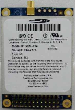
KNYAMI0032AT
Dec 12, 2013GXM-T14, GXM-T24
Equipment Class
DSS - Part 15 Spread Spectrum Transmitter