KNYLRS455CLR455C
FreeWave Technologies Inc.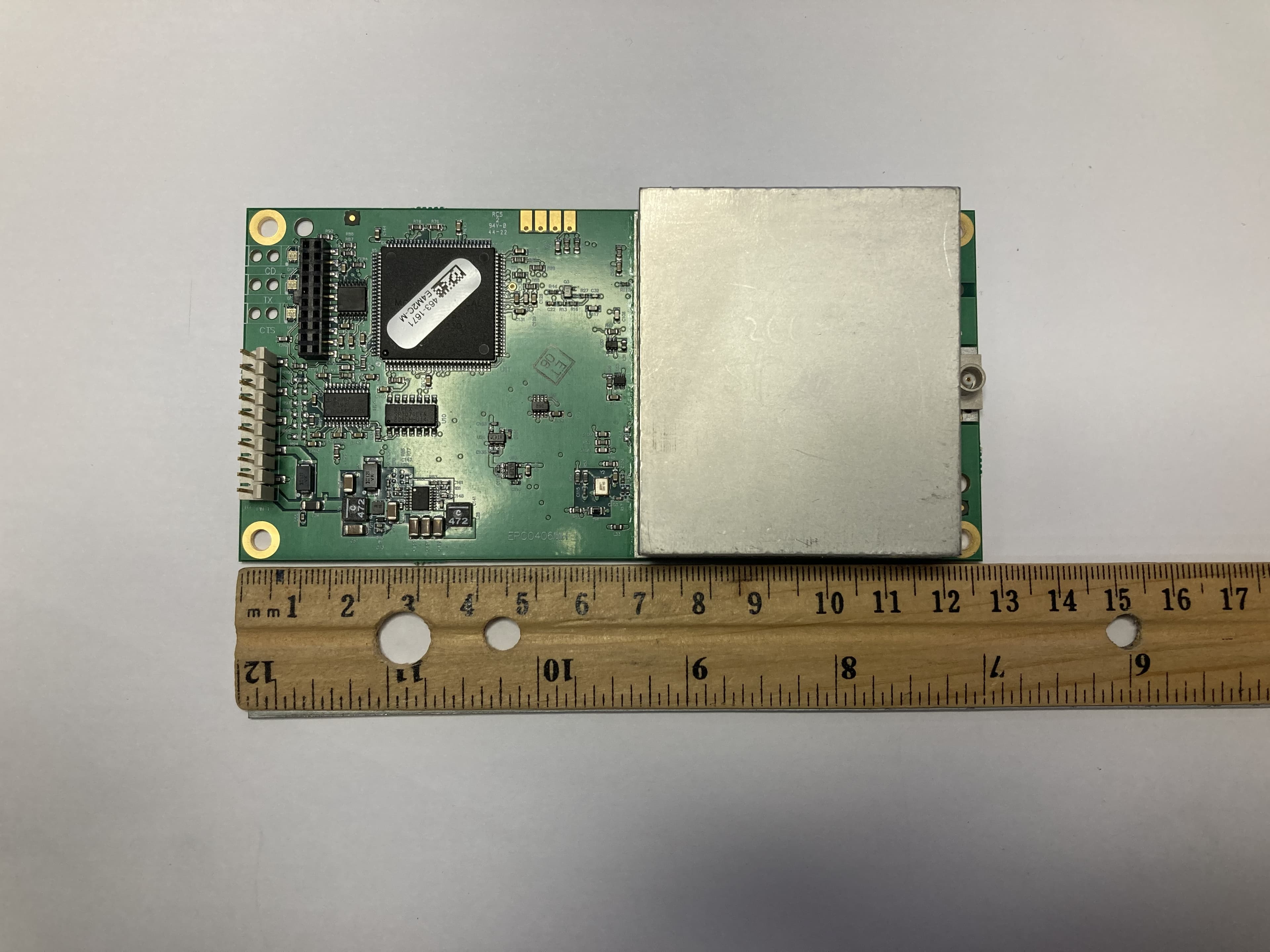
Click to zoom
Application Details
- Equipment Class
- TNB - Licensed Non-Broadcast Station Transmitter
- Date of Grant
- Oct 01, 2023
- Application Purpose
- Original Equipment
- Date of Application
- Sep 28, 2023
- Equipment Note
- LR455C
- Frequency Range
- 435.00000000 - 470.00000000
- Company
- FreeWave Technologies Inc.
- Country
- United States
Documents & Files
Document Text
Text extracted from the exhibit documents filed with the FCC. Open a document above to read the original.
Users Manual
FreeWave Technologies March 20, 2023 FCC notifications 400 MHz Licensed Installation Manual REVA This device complies with part 15 of the FCC rules. Operation is subject to the following two conditions: 1. This device may not cause harmful interference and 2. This device must accept any interference received, including interference that may cause undesired operation. The content of this guide covers Free Wave Technologies, Inc. models sold under FCC ID: KNYLRS455C. All models sold under the FCC ID(s) listed above must be installed professionally and are only approved for use when installed in devices produced by Free Wave Technologies or third party OEMs with the express written approval of Free Wave Technologies, Inc. Changes or modifications should not be made to the device. Warning! The transceivers covered in this guide have a maximum transmitted output power of 2 W. The antennas used must provide a separation distance of at least 72 cm from all persons and must not be co-located or operate in conjunction with any other antenna or transmitter. Antennas used with the transceiver must not exceed 7 dBi. The models described in this guide must be installed in a NEMA enclosure. When any Free Wave Technologies, Inc. module is placed inside an enclosure, a label must be placed on the outside of the enclosure. The label must include t he text "Contains FCC ID: KNYLRS455c." F CC §90.203(g) (g): The transmitter is programmed for frequencies through controls normally inaccessible to the operator. RSS-119; 3.2: The transmitter is programmed for frequencies through controls that are inaccessible to the user. LIG00l lAC Rev A 4 of7
Users Manual
LRS455 Wireless Data Radio LRS455C Covering Firmware 1.80 User-Reference Manual Part Number: LUM0016AC Revision: Mar-2023 LRS455C User-Reference Manual LUM0016AC Rev Mar-2023 Page 2 of 99 Copyright © 2023 FreeWave This document is subject to change without notice. This document is the property of FreeWave Technologies, Inc. and contains proprietary information owned by FreeWave. This document cannot be reproduced in whole or in part by any means without written permission from FreeWave Technologies, Inc. Safety Information The products described in this manual can fail in a variety of modes due to misuse, age, or malfunction and is not designed or intended for used in systems requiring fail-safe performance, including life safety systems. Systems with the products must be designed to prevent personal injury and property damage during product operation and in the event of product failure. FreeWave Technologies, Inc. warrants the FreeWave® LRS455C Wireless Data Radio (Product) that you have purchased against defects in materials and manufacturing for a period of three years from the date of shipment, depending on model number. In the event of a Product failure due to materials or workmanship, FreeWave will, at its discretion, repair or replace the Product. For evaluation of Warranty coverage, return the Product to FreeWave upon receiving a Return Material Authorization (RMA). The replacement product will remain under warranty for 90 days or the remainder of the original product warranty period, whichever is longer. IN NO EVENT WILL FREEWAVE TECHNOLOGIES, INC., ITS SUPPLIERS, OR ITS LICENSORS BE LIABLE FOR ANY DAMAGES ARISING FROM THE USE OF OR INABILITY TO USE THIS PRODUCT. THIS INCLUDES BUSINESS INTERRUPTION, LOSS OF BUSINESS INFORMATION, INABILITY TO ACCESS OR SEND COMMUNICATION OR DATA, PERSONAL INJURY OR DAMAGE, OR OTHER LOSS WHICH MAY ARISE FROM THE USE OF THIS PRODUCT. THE WARRANTY IS EXCLUSIVE AND ALL OTHER WARRANTIES EXPRESS OR IMPLIED , INCLUDING BUT NOT LIMITED TO ANY WARRANTIES OF MERCHANTABILITY OR FITNESS FOR A PARTICULAR USE ARE EXPRESSLY DISCLAIMED . FreeWave’s Warranty does not apply in the following circumstances: 1. If Product repair, adjustments, or parts replacements are required due to accident, neglect, or undue physical, electrical, or electromagnetic stress. 2. If Product is used outside of FreeWave specifications as stated in the Product's data sheet. 3. If Product has been modified, repaired, or altered by Customer unless FreeWave specifically authorized such alterations in each instance in writing. Where applicable, this includes the addition of conformal coating. FreeWave Technologies, Inc. 5395 Pearl Parkway, Boulder, CO 80301 303.381.9200 Toll Free: 1.866.923.6168 Fax: 303.786.9948 LRS455C User-Reference Manual LUM0016AC Rev Mar-2023 Page 3 of 99 Copyright © 2023 FreeWave This document is subject to change without notice. This document is the property of FreeWave Technologies, Inc. and contains proprietary information owned by FreeWave. This document cannot be reproduced in whole or in part by any means without written permission from FreeWave Technologies, Inc. Table of Contents 1. Preface ..................................................................................................................................................... 7 2. Overview .................................................................................................................................................. 9 2.1. Choosing a Location for the Radios ............................................................................................... 10 2.2. Choosing Point-to-Point or Point-to-MultiPoint Operation .......................................................... 10 2.3. Examples of Data Communication Links ....................................................................................... 11 1.3.1. Example 1 - Point-to-Point Link ................................................................................................. 12 1.3.2. Example 2 - Point-to-Point Link with Repeater ......................................................................... 12 Figure 3: Point-to-Point Link with a Repeater ....................................................................................... 12 1.3.3. Example 3 - Standard Point-to-Multipoint Network ................................................................. 13 3. Equipment ............................................................................................................................................. 14 3.1. Included Equipment ...................................................................................................................... 14 3.2. User-supplied Equipment .............................................................................................................. 14 3.3. Finding the Product Serial Number ................................................................................................... 14 4. Installation ............................................................................................................................................. 15 4.1. Power the Radio ............................................................................................................................ 16 4.2. Radio Setup Mode ......................................................................................................................... 16 4.2.1. Use Tool Suite to Connect to and Program Radios ................................................................... 16 4.3. Procedure ...................................................................................................................................... 16 4.3.1. Access the Setup Menu using a Terminal Emulator in Tool Suite ............................................. 18 4.4. Procedure .............................................................................................................................…
Text truncated - open the document above for the full version.
Users Manual
FreeWave Technologies March 20, 2023 FCC notifications 400 MHz Licensed Installation Manual REVA This device complies with part 15 of the FCC rules. Operation is subject to the following two conditions: 1. This device may not cause harmful interference and 2. This device must accept any interference received, including interference that may cause undesired operation. The content of this guide covers Free Wave Technologies, Inc. models sold under FCC ID: KNYLRS455C. All models sold under the FCC ID(s) listed above must be installed professionally and are only approved for use when installed in devices produced by Free Wave Technologies or third party OEMs with the express written approval of Free Wave Technologies, Inc. Changes or modifications should not be made to the device. Warning! The transceivers covered in this guide have a maximum transmitted output power of 2 W. The antennas used must provide a separation distance of at least 72 cm from all persons and must not be co-located or operate in conjunction with any other antenna or transmitter. Antennas used with the transceiver must not exceed 7 dBi. The models described in this guide must be installed in a NEMA enclosure. When any Free Wave Technologies, Inc. module is placed inside an enclosure, a label must be placed on the outside of the enclosure. The label must include t he text "Contains FCC ID: KNYLRS455c." F CC §90.203(g) (g): The transmitter is programmed for frequencies through controls normally inaccessible to the operator. RSS-119; 3.2: The transmitter is programmed for frequencies through controls that are inaccessible to the user. LIG00l lAC Rev A 4 of7
Attestation Statements
Sample US Agent Attestation Letter TO: Federal Communications Commission Authorization and Evaluation Division 7435 Oakland Mills Road Columbia, Maryland 21046 Re: section 2.911(d)(7) filing To whom it may concern, This letter is to confirm that [Richard Reisbick] has accepted responsibility to act as the agent for service of process as acknowledged by the applicant, [FREEWAVE Technologies Inc.]. [Richard Reisbick] confirms he is not associated with or part of any TCB or test lab. U.S. Agent: Richard Reisbick Title: VP of Engineering Company Name: FREEWAVE Technologies Inc. Address: 5395 Pearl Parkway, Suite 100. Boulder Colorado 80301 Telephone No: 3033819200 Email: [email protected] FRN (FCC Registration Number): 0024140386 The applicant accepts and acknowledges the obligation to maintain an agent for no less than one year after the grantee has terminated all marketing and importation or the conclusion of any Commission-related proceeding involving the equipment. Signature of Applicant (must be signed by the contact of record in the FCC database for the applicant grantee code): Signature of U.S. Agent (if different from applicant): Name: Richard Reisbick Name: Date:7/17/2023 Date:
Cover Letter(s)
41039 Boyce Road 510-578-3500 Phone Fremont, CA. 94538 Page 1 of 1 September 25, 2023 Federal Communications Commission Office of Engineering and Technology Laboratory Division 7435 Oakland Mills Road Columbia, MD 21046 Innovation Science and Economic Development Canada Certification and Engineering Bureau 3701 Carling Avenue, Building 94 Ottawa, Ontario K2H 8S2 FCC ID: KNYLRS455C IC: 2329B-LRS455C To whom it may concern: The enclosed documents constitute a formal submittal and application for a full Modular FCC Equipment Authorization and ISED Canada Certification (original application) for a licensed radio module pursuant to the following rules: Part 90 of FCC Rules (CFR 47), Subpart I, Equipment class: TNB RSS-Gen Issue 5, April 2018, “General Requirements for Compliance of Radio Apparatus” RSS-119, Issue 12, May 2015, “Land Mobile and Fixed Equipment Operating in the Frequency Range 27.41-960 MHz”, Equipment type: Land Mobile Radio - Mobile This radio must be installed professionally and are only approved for use when installed in devices produced by FreeWave Technologies or third party OEMs with the express written approval of FreeWave Technologies, Inc. It is not sold to the general public. Certification is requested for operation in the 450-470 MHz frequency band in Canada and 435- 470 MHz for the US. National Technical Systems, as duly authorized agent prepared this submittal. A copy of the letter of our appointment as agent is included with the application. If there are any questions or if further information is needed, please contact National Technical Systems for assistance. Sincerely, David W. Bare Chief Engineer
Cover Letter(s)
Agent Authorization Letter Date 4/10/2023 To whom it may concern, We, the undersigned, hereby authorize (NTS labs) to act on our behalf, as our agent, in the following matters related to the FCC and/or Innovation Science and Economic Development Canada approval of our products: report submittal, related correspondence, the signing of all documents relating to these matters, and any other lawful activity necessary to obtain such certification. Any act carried out by David Bare of NTS labs LLC w ithin the scope of this authorization shall have the same affect as our own. This authorization shall expire 12 months from original date. S incerely, Richard Reisbick VP Engineering FREEWAVE Technologies Inc. Office: +1-303-381-92 00 Email: [email protected] www .FreeWave.com 5395 Pearl Parkway, Suite 100. Boulder Colorado 80301
ID Label/Location Info
Corporate Office: 1097 N. Batavia St. Orange, CA 92867Material Specification Sheet 800.429.4321www.labeltronix.com Fax 800.419.1555 LTX 600Thermal Transfer Gloss White Polyester Product Description A general purpose, high performance polyester label film. LTX 600 is UL/CSA approved, when printed with a LABEL TRONIX® 500 Plus™ ribbon under UL# MH26576. This facestock resists tearing, abrasion and heat. The gloss white surface makes label graphics easy to read. Facestock Description A gloss, topcoated, thermal transfer printable, white polyester. Static dissipating properties reduce print voids in thermal transfer printing, which are due to static generated at the printhead. Test Property .....................................................................Typical Values Type ....................................................................................Gloss White Polyester Caliper (mils) .......................................................................2.0 ± 10% Ribbon Compatibility............................................................500 Plus™ Adhesive Description An aggressive, high performance permanent adhesive. This adhesive offers high initial tack, high shear, and high ultimate bond to a wide variety of surfaces. Test Property .....................................................................Typical Values Type ....................................................................................General Purpose Acrylic Application Temperature (Minimum)....................................50 ̊F Service Temperature Range ...............................................-40 ̊F to 302 ̊F Liner Description Test Property .....................................................................Typical Values Type ....................................................................................Bleached Kraft Caliper (mils) .......................................................................3.1 ± 10% Recommendations • One-year shelf life from receipt of material, if properly stored. • Recommended storage conditions are 72°F (22°C) and 50% relative humidity. • Good for use in: UL rating plates and nameplates, material tracking, under the hood labels, parts identification, and asset management labels. As with all pressure-sensitive materials, LABELTRONIX recommends this product be tested thoroughly under end-use conditions to make sure it meets the requirements of the specific application. ∗ ∗∗ ∗Please note that the above data represents expected averages with variances following industry standards. They should not be misinterpreted as minimum or absolute values. This specification sheet was updated and confirmed as of 11/01/01.
RF Exposure Info
EMC Test Data Client: Contact: Standard: Specific Details General Test Configuration No 72US 95Canada FreeWave Technologies, Inc.PR Number: PR167383 Model: LRS455C T-Log Number: TL167383-RANA Project Manager: Deepa Shetty Ofer FisherProject Engineer: David Bare FCC Parts 15 & 90, RSS-119; EN55032Class: N/A Deviations From The Standard Maximum Permissible Exposure / SAR Exclusion Objective: Evaluate the RF Exposure requirements per FCC 1.1310, 2.1091 and RSS-102. Date of Test: 12/22/2022 Calculation uses the free space transmission formula: S = (PG)/(4 πd 2 ) Where: S is power density (W/m 2 ), P is output power (W), G is antenna gain relative to isotropic, d is separation distance from the transmitting antenna (m). Summary of Results Device complies with Power Density requirements at 20cm separation: If not, required separation distance (in cm): Test Engineer: David Bare No deviations were made from the requirements of the standard. If not, required separation distance (in cm): TL167383-RANA.xlsMPE CalcPage 1 of 2 EMC Test Data Client: Contact: Standard: FreeWave Technologies, Inc.PR Number: PR167383 Model: LRS455C T-Log Number: TL167383-RANA Project Manager: Deepa Shetty Ofer FisherProject Engineer: David Bare FCC Parts 15 & 90, RSS-119; EN55032Class: N/A FCC MPE Calculation Use: General Antenna: Maximum 9.25 dBi Cable Loss AntPower Freq.LossGainat AntEIRP MHzdBmmW*dBdBidBmmW 43533.52238.709.2533.518836.49 45033.52238.709.2533.518836.49 47033.52238.709.2533.518836.49 For the cases where S > the MPE Limit Fre q. MHz 435 450 470 Industry Canada MPE Calculation Use: General Antenna: Maximum 9.25 dBi Cable Loss AntPower Freq.LossGainat AntEIRP MHzdBmmW*dBdBidBmmW 45033.52238.709.2533.518836.49 46033.52238.709.2533.518836.49 47033.52238.709.2533.518836.49 For the cases where S > the MPE Limit Fre q. MHz 450 460 470 mW/cm^2mW/cm^2 0.289 EUTPower Density (S)MPE Limit Power (in. Tolerance)at 72 cmat 72 cm Power Density (S)MPE LimitDistance where 0.290 0.2890.313 0.2890.300 mW/cm^2mW/cm^2cm at 95 cmat 95 cmS <= MPE Limit 0.2890.30070.7 0.2890.29071.9 EUTPower Density (S)MPE Limit 0.2890.31369.2 Power (in. Tolerance)at 95 cmat 95 cm 1.6611.703 W/cm^2W/cm^2 1.6611.755 1.6611.729 mW/cm^2mW/cm^2cm Power Density (S)MPE LimitDistance where at 95 cmat 95 cmS <= MPE Limit 1.6611.70393.8 1.6611.75592.4 1.6611.72993.1 TL167383-RANA.xlsMPE CalcPage 2 of 2
Test Report
Directional yagi antennas y(s)4503 Features and BeneFits: • All UHF and higher frequency models are delivered fully assembled. • All radial elements are secured to the boom with stainless steel hardware to prevent corrosion. • Every Yagi is tuned on a network analyzer for best power match and lowest VSWR. • All antennas ship complete with a mounting kit that includes stainless steel hardware. applications: • Point-to-point and multi-point / omnidirectional outdoor antenna applications used by private organizations and government agencies around the globe. • Typical applications include transportation such as railroad switching, remote locations reporting examples that include oil fields, weather conditions and, meter data transmissions for utilities. Laird Silver Series Yagi antennas represent great value while featuring the same great optimized design and plated brass connector found on premium gold series models. Each Yagi is factory tuned on a network analyzer for best power match and lowest VSWR, offering the best possible performance every time. All antennas ship complete with a mounting kit that includes stainless steel hardware. silver series directional yagi antennas comBine optimized design Features with great value ANT-DS-Y(S)4503 0615 Any information furnished by Laird Inc. and its agents is believed to be a ccurate and reliable.All specifications are subject to change without notice.Responsibility for the use and application of Laird materials rests with the end user, since Laird and its agents cannot be aware of all potential uses. Laird makes no warranties as to the fitness, merchantability or suitability of any Laird materials or products for any specific or general uses. Laird shall not be liable for incidental or consequential damages of any kind. All Laird products are sold pursuant to the Laird Terms and Conditions of sale in effect from time to time, a copy of which will be furnished upon request. © Copyright 2015 Laird Inc. All Rights Reserved. Laird, Laird Technologies, the Laird Technologies Logo, and other marks are trade marks or registered trade marks of Laird Inc. or an affiliate company thereof. Other product or service names may be the property of third parties. Nothing herein provides a license under any Laird or any third party intellectual property rights. electrical Frequency Range450 – 470 MHz VSWR< 2:1 Return Loss-10 dB max Nominal Gain7.1 dBd Front to Back Ratio17 dBd Maximum Power300 W Nominal Impedance50 Ω Polarization Vertical or Horizontal PatternDirectional Horizontal Beamwidth (For Horizontal Polarization) 115° Vertical Beamwidth (For Vertical Polarization) 114° TuningNA Transmitting/ReceivingBoth Mechanical MaterialAluminum Length20-3/16” Height13-1/2” Boom Diameter7/8” Weight1.15 lbs Rated Wind Velocity150 mph (241 kph) Rated Wind Velocity (with 0.5” radial ice) 80 mph (130 kph) Equivalent Flat Area0.2177 sq. ft. CableNone TerminationN-Female connector ColorSilver Only for YS series Lightning Protection Lightning Arrestor LABH350NN (Sold Separately) Mounting Included Yagi mounting kit included for 7/8” boom Vertical-to-Vertical Polarization azimuthal Pattern (y , Z, or e-plane) Horizontal-to-Horizontal Polarization azimuthal Pattern (y , Z, or H-plane) normalized to 7.1 dBd normalized to 7.1 dBd Americas: +1.847 839.6907 [email protected] Europe: +44.1628.858941 [email protected] Asia: +86.21.5855.0827.127 [email protected] www.lairdtech.com
Test Report
A Laird Connectivity’s directional gamma matched Yagi antennas are focused on economical and high performance. This UHF Yagi series has a 9.1 dBi antenna gain and operates on the 430-450 MHz frequency range. It is manufactured using high strength 6061-T6 aluminum to withstand heavy ice, high wind, and other harsh conditions. ▪ Every Yagi is tuned on a network analyzer for best power match and lowest VSWR. ▪ All Yagi antennas ship complete with a high- quality cast aluminum mounting kit that includes stainless steel hardware and allows vertical or horizontal orientation during installation (VHF models require light assembly). ▪ Point-to-point directional and multiple point to omnidirectional outdoor antenna applications used by private organizations and government agencies around the globe. ▪ Typical applications include transportation such as railroad switching, remote locations reporting examples that include oil fields and weather conditions and meter data transmissions for utilities. Model Name YS4303 Operating Frequency (MHz) 430-450 VSWR < 2:1 Return Loss – Max (dB) -10 Gain (dBi) 9.1 Nominal Impedance (Ohms) 50 Max Power - Ambient 25°C (W) 300 Polarization Vertical or horizontal Pattern Directional Vertical Plane 3 dB Beamwidth 114° Horizontal Plane 3 dB Beamwidth 115° Tuning Fixed tune Transmitting/Receiving Both Front-to-Back Ratio (dB) 17 Dimensions – L x H – cm (inches) 51.4 x 34.6 (20.3 x 13.6) Boom Diameter – cm (inches) 2.22 (0.875) Material Aluminum Color Silver Lightning Protection Lightning arrestor – LABH350NN (sold separately) Mounting Yagi mounting kit Operating Environment (Indoor or Outdoor) Outdoor Operating Temperature – °C (°F) -30 to +70°C (-22 to +158°F) Storage Temperature – °C (°F) -30 to +70°C (-22 to +158°F) Rated Wind Velocity – km/hr (mph) 241 (150) Equivalent Flat Area – sq. m (sq. ft.) 0.04470 (0.48115) YS4303 N/A N-Female [email protected] [email protected] www.lairdconnect.com Laird Connectivity warrants to the original end user customer of its products that its products are free from defects in material and workmanship. Subject to conditions and limitations Laird Connectivity will, at its option, either repair or replace any part of its products that prove defective because of improper workmanship or materials. This limited warranty is in force for the useful lifetime of the original end product into which the Laird Connectivity product is installed. Useful lifetime of the original end product may vary but is not to exceed five (5) years from the original date of the end product purchase. Any information furnished by Laird Connectivity and its agents is believed to be accurate and reliable. All specifications are subject to change without notice. Responsibility for the use and application of Laird Connectivity materials rests with the end user, since Laird Connectivity and its agents cannot be aware of all potential uses. Laird Connectivity makes no warranties as to the fitness, merchantability or suitability of any Laird Connectivity materials or products for any specific or general uses. Laird Connectivity shall not be liable for incidental or consequential damages of any kind. All Laird Connectivity products are sold pursuant to the Laird Connectivity Terms and Conditions of sale in effect from time to time, a copy of which will be furnished upon request. © Copyright 2020 Laird Connectivity All Rights Reserved. Laird Connectivity, the Laird Connectivity logo, and other marks are trademarks or registered trademarks of Laird Connectivity or an affiliate company thereof. Other product or service names may be the property of third parties. Nothing herein provides a license under any Laird Connectivity or any third party intellectual property rights.
Test Report
41039 Boyce Road Fremont, CA. 94538 510-578-3500 Phone File: FR-167383.02-NA Rev 2 Page 1 Radio Test Report FCC Part 90 and RSS-119 (USA: 435 MHz to 470 MHz) (Canada: 450 MHz to 470 MHz) Model: LRS455C IC CERTIFICATION #: 2329B-LRS455C FCC ID: KNYLRS455C COMPANY: FreeWave Technologies, Inc. 5395 Pearl Parkway, Suite 100 Boulder, CO 80301 TEST SITE(S): NTS Labs LLC 41039 Boyce Road. Fremont, CA. 94538-2435 PROJECT NUMBER: PR167383 REPORT DATE: January 9, 2023 RE-ISSUED DATE: September 25, 2023 FINAL TEST DATES: December 28 and 29, 2022 and January 3 and 4, 2023 TOTAL NUMBER OF PAGES: 53 This report and the information contained herein represent the results of testing of only those articles / products identified in this document and selected by the client. The tests were performed to specifications and/or procedures selected by the client. NTS Labs LLC makes no representations expressed or implied that such testing fully demonstrates efficiency, performance, reliability, or any other characteristic of the articles being tested, or similar products. This report should not be relied upon as an endorsement or certification by NTS Labs LLC of the equipment tested, nor does it present any statement whatsoever as to its merchantability or fitness of the test article or similar products, for a particular purpose. This report shall not be reproduced except in full without written approval from NTS Labs LLC. NTS Labs LLC Project number PR167383 Report Date: January 9, 2023, Re-Issue Date: September 25, 2023 Test Report FR-167383.02-NA Rev 2 Page 2 VALIDATING SIGNATORIES PROGRAM MGR _________________________ David W. Bare Chief Engineer TECHNICAL REVIEWER: _________________________ David W. Bare Chief Engineer FINAL REPORT PREPARER: _________________________ David Guidotti Senior Technical Writer QUALITY ASSURANCE DELEGATE _________________________ Gary Izard Senior Technical Writer NTS Labs LLC Project number PR167383 Report Date: January 9, 2023, Re-Issue Date: September 25, 2023 Test Report FR-167383.02-NA Rev 2 Page 3 REVISION HISTORY Rev# Date Comments Modified By - January 9, 2023 First release 1 September 25, 2023 Updated to add interface impedance, spectrum efficiency and minimum data rate statements, remove highlights, correct the ERP calculations, separate FCC and ISED summary tables, change a reference to C63.10 to C63.26 and add additions annotations to the transient frequency behavior plots David Bare 2 September 25, 2023 Corrected ERP values David Bare NTS Labs LLC Project number PR167383 Report Date: January 9, 2023, Re-Issue Date: September 25, 2023 Test Report FR-167383.02-NA Rev 2 Page 4 TABLE OF CONTENTS COVER PAGE ............................................................................................................................................................. 1 VALIDATING SIGNATORIES ................................................................................................................................. 2 REVISION HISTORY ................................................................................................................................................ 3 TABLE OF CONTENTS ............................................................................................................................................ 4 SCOPE .......................................................................................................................................................................... 5 OBJECTIVE ................................................................................................................................................................ 6 STATEMENT OF COMPLIANCE ........................................................................................................................... 6 DEVIATIONS FROM THE STANDARDS .............................................................................................................. 6 TEST RESULTS .......................................................................................................................................................... 7 FCC PART 90 AND RSS-119 .................................................................................................................................... 7 EXTREME CONDITIONS ...................................................................................................................................... 8 MEASUREMENT UNCERTAINTIES .................................................................................................................... 9 EQUIPMENT UNDER TEST (EUT) DETAILS ..........................................................................…
Text truncated - open the document above for the full version.
Contact Information
Applicant
Richard Reisbick(VP Engineering)
Test Firm
Element Materials Technology Fremont NewarkDavid Bare
Technical Specifications
| # | Rule Parts | Frequency Range | Power Output | Emission | Tolerance |
|---|---|---|---|---|---|
| 2 | 90.21 | 435 MHz - 470 MHz | 1.95 W | 7K59F1D | 1.5 ppm |
Other Applications from FreeWave Technologies Inc.
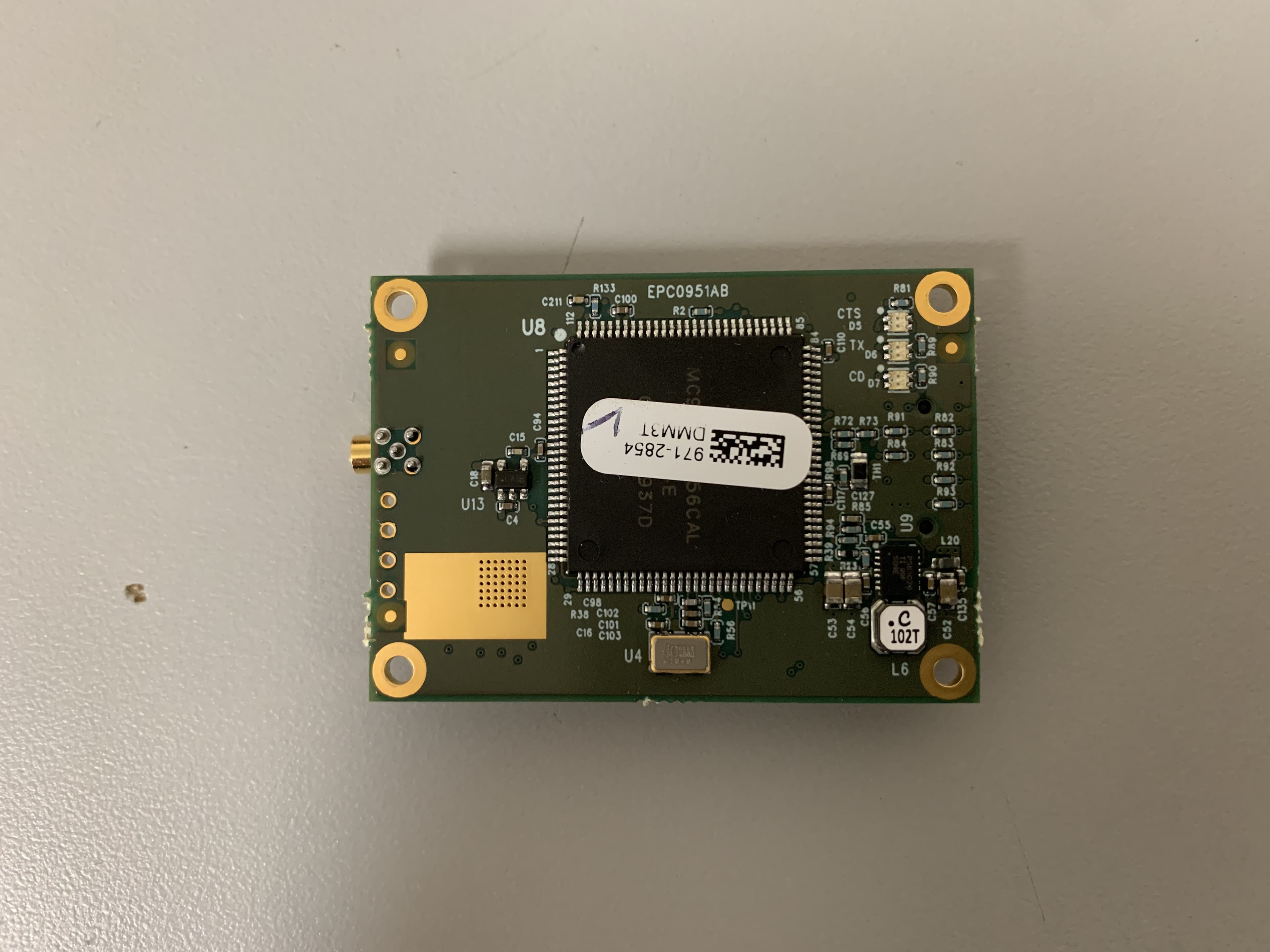
KNYMM3
Aug 25, 2020FHSS 902 - 928 MHz ISM band radio
Equipment Class
DSS - Part 15 Spread Spectrum Transmitter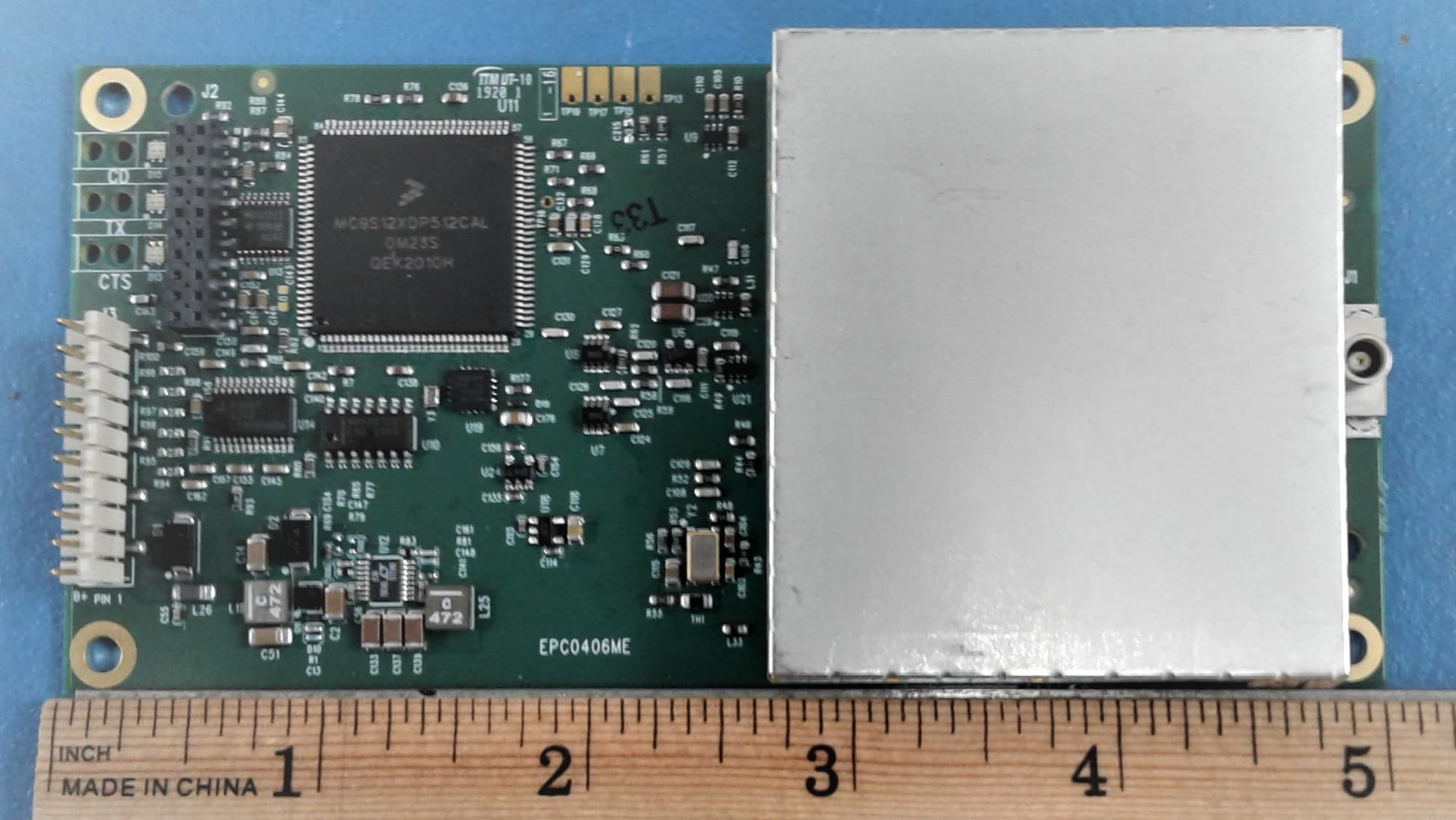
KNYLRS455A
Aug 04, 2020435-470 MHz Licensed Band Transceiver,
Equipment Class
TNB - Licensed Non-Broadcast Station Transmitter
KNYPRW5000AA
Oct 22, 2015Wireless 802.11ac/b/g/n access point
Equipment Class
DTS - Digital Transmission System
KNYAMM0921TT
Jan 14, 2014MM2
Equipment Class
DSS - Part 15 Spread Spectrum Transmitter
KNYAMI0032AT
Dec 12, 2013GXM-T14, GXM-T24
Equipment Class
DSS - Part 15 Spread Spectrum Transmitter