KNY-42182112519902MHz to 928MHz Transceiver
FreeWave Technologies Inc.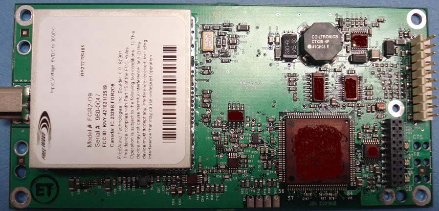
Click to zoom
Application Details
- Equipment Class
- DSS - Part 15 Spread Spectrum Transmitter
- Date of Grant
- Feb 06, 2008
- Application Purpose
- Original Equipment
- Date of Application
- Feb 06, 2008
- Equipment Note
- 902MHz to 928MHz Transceiver
- Frequency Range
- 902.25000000 - 927.82000000
- Company
- FreeWave Technologies Inc.
- Country
- United States
Documents & Files
Document Text
Text extracted from the exhibit documents filed with the FCC. Open a document above to read the original.
Users Manual
Spread Spectrum Wireless Data Transceiver User Manual LUM0002AG Rev A Version 7.0 i Spread Spectrum Wireless Data Transceiver User Manual Version 7.0 FreeWave Technologies, Inc. 1880 South Flatiron Court Boulder, CO 80301 (303) 444-3862 (303) 786-9948 Fax www.FreeWave.com S PREAD SPECTRUM WIRELESS DATA TRANSCEIVER USER MANUAL Copyright © 1995-2008 by FreeWave Technologies, Inc. All rights reserved. Published 2008. Spread Spectrum Wireless Data Transceiver User Manual LUM0002AG Rev A Version 7.0 ii W ARRANTY FreeWave Technologies warrants the FreeWave Wireless Data Transceiver against defects in materials and manufacturing for a period of two years from the date of purchase. In the event of a Product failure due to materials or workmanship, FreeWave will, at its discretion, repair or replace the Product. In no event will FreeWave Technologies Inc., its suppliers, and its licensors be liable for any damages arising from the use of or inability to use this Product. This includes business interruption, loss of business information, or other loss which may arise from the use of this Product. Please be advised that OEM customer’s warranty periods may vary. Warranty Policy may not apply: 1. If Product repair, adjustments or parts replacements is required due to accident, neglect, unusual physical, electrical or electromagnetic stress. 2. If Product is used outside of FreeWave specifications. 3. If Product has been modified, repaired or altered by Customer unless FreeWave specifically authorized such alterations in each instance in writing. This includes the addition of conformal coating. The Warranty period begins from the date of shipment and is defined per the Standard Warranty Policy stated above. Special Rate Replacement Option A special rate replacement option is offered to non-warranty returns or upgrades. The option to purchase the replacement unit at this special rate is only valid for that RMA, (Return Material Authorization). The special replacement rate option expires if not exercised within 30 days of final disposition of RMA. R ESTRICTED RIGHTS Microsoft and Windows are registered trademarks of the Microsoft Corporation. pcANYWHERE is a registered trademark of Symantec Corporation. Other product names mentioned in this manual may be copyrights, trademarks, or registered trademarks of their respective companies and are hereby acknowledged. Information in this document is subject to change without notice. The information contained in this document is proprietary and confidential to FreeWave Technologies, Inc. This manual is for use by purchasers and other authorized users of the FreeWave™ Spread Spectrum Wireless Data Transceiver only. No part of this document may be reproduced or transmitted in any form or by any means, electronic or mechanical, or for any purpose without the express written permission of FreeWave Technologies, Inc. FreeWave’s Spread Spectrum Wireless Data Transceivers are made in the United States of America. Printed in the United States of America. Spread Spectrum Wireless Data Transceiver User Manual LUM0002AG Rev A Version 7.0 iii This product is licensed by The United States. Diversion contrary to U.S. law is prohibited. Shipment or re-export of this product outside of The United States may require authorization by the U.S. Bureau of Export Administration. Please contact FreeWave Technologies for assistance and further information. UL NOTIFICATION Model# FGR2 is undergoing testing to be suitable for use in Class 1, Division 2, Groups A, B, C, and D or non-hazardous locations only. Input voltage for Model# FGR2 is 6 to 30 volts DC. Model# FGRO9CSU is suitable for use in Class 1, Division 2, Groups A, B, C, and D or non-hazardous locations only. Input voltage for Model# FGRO9CSU is 6 to 30 volts DC. Model# DGRO9RFS is suitable for use in Class 1, Division 2, Groups A, B, C, and D or non-hazardous locations only. Input voltages for Model# DGRO9RFS are determined by the label on the bottom of the board. If the board has Label A shown below the input voltage is 6 to 14 volts DC. If the board has Label B shown below the input voltage is 6 to 14 volts DC at a maximum baud rate of 57.6 KBaud or 6 to 18 volts DC at a maximum baud rate of 19.2 KBaud, operation mode of MultiPoint Slave or MultiPoint Slave/Repeater only. Spread Spectrum Wireless Data Transceiver User Manual LUM0002AG Rev A Version 7.0 iv FCC NOTIFICATIONS This device complies with part 15 of the FCC rules. Operation is subject to the following two conditions: 1) This device may not cause harmful interference and 2) this device must accept any interference received, including interference that may cause undesired operation. This device must be operated as supplied by FreeWave Technologies, Inc. Any changes or modifications made to the device without the express written approval of FreeWave Technologies may void the user's authority to operate the device. CAUTION: The FGR series transceivers have a maximum transmitted output power of 955mW. The FGR2 series transceivers have a maximum transmitted output power of 1000mW. It is recommended that the transmit antenna be kept at least 23 cm away from nearby persons to satisfy FCC RF exposure requirements. The “I”-series transceiver have maximum transmitted output power of 500mW. It is recommended that the transmit antenna be kept at least 23 cm away from nearby persons to satisfy FCC RF exposure requirements. This equipment has been tested and found to comply with the limits for a Class B digital device, pursuant to part 15 of the FCC Rules. These limits are designed to provide reasonable protection against harmful interference in a residential installation. This equipment generates, uses, and can radiate radio frequency energy and, if not installed and used in accordance with the instructions, may cause harmful interference to radio communications. However, no guarantee shall be made that interference will not occur in a particular installation. If this equipment…
Text truncated - open the document above for the full version.
Users Manual
High Throughput Wireless Data Transceiver Installation Guide LIG000^AA Rev A 1 of 7 900 MHz High Throughput Wireless Ethernet Terminal Server (Model HT2+) Installation Guide V1.0a FreeWave Technologies, Inc. 1880 South Flatiron Court Boulder, CO 80301 (303) 444-3862 (303) 786-9948 Fax www.FreeWave.com SPREAD SPECTRUM WIRELESS DATA TRANSCEIVER INSTALLATION GUIDE Copyright © 1995-2008 by FreeWave Technologies, Inc. All rights reserved. Published 2008. High Throughput Wireless Data Transceiver Installation Guide LIG000^AA Rev A 2 of 7 FreeWave Technologies, Inc. 900 MHz High Throughput Wireless Ethernet Terminal Server Installation Guide This installation guide covers all models of the FreeWave Technologies 900 MHz High Throughput DST transceivers sold under FCC ID KNY-42182112519. All transceiver models sold under FCC ID KNY-42182112519 must be installed professionally. This transceiver is only approved for use when installed in devices produced by FreeWave Technologies or third party OEMs approved by FreeWave Technologies. The antenna(s) to be used must be installed to provide a separation distance of at least 23cm from all persons and must not be co-located or operating in conjunction with any other antenna or transmitter. This transceiver must be installed in a NEMA enclosure. High Throughput Wireless Data Transceiver Installation Guide LIG000^AA Rev A 3 of 7 FCC Notification This device complies with part 15 of the FCC rules. Operation is subject to the following two conditions: 1) This device may not cause harmful interference and 2) this device must accept any interference received, including interference that may cause undesired operation. This device must be operated as supplied by FreeWave Technologies, Inc. Any changes or modifications made to the device without the express written approval of FreeWave Technologies may void the user's authority to operate the device. CAUTION: This device has a maximum transmitted output power of 1W (30 dBm). It is required that the transmit antenna be kept at least 23 cm away from nearby persons to satisfy FCC RF exposure requirements. Note: This equipment has been tested and found to comply with the limits for a Class B digital device, pursuant to part 15 of the FCC Rules. These limits are designed to provide reasonable protection against harmful interference in a residential installation. This equipment generates, uses and may radiate radio frequency energy and, if not installed and used in accordance with the instructions, may cause harmful interference to radio communications. However, there is no guarantee that interference will not occur in a particular installation. If this equipment does cause harmful interference to radio or television reception, which can be determined by turning the equipment off and on, the user is encouraged to try to correct the interference by one or more of the following measures: ♦ Reorient or relocate the receiving antenna. ♦ Increase the separation between the equipment and receiver. ♦ Connect the equipment into an outlet on a circuit different from that to which the receiver is connected. ♦ Consult the dealer or an experienced radio/TV technician for help. Note: Whenever any FreeWave Technologies module is placed inside an enclosure a label must be placed on the outside of that enclosure which includes the module's FCC ID. UL Notification Model# HT2+ is not UL approved at this time. High Throughput Wireless Data Transceiver Installation Guide LIG000^AA Rev A 4 of 7 A. Transceiver installation steps To install the HT2+ series transceivers, follow the basic steps given below. 1. Mount the transceiver to the flat, stable surface using mounting holes in the case of the enclosure. Transceiver models sold under FCC ID KNY-42182112519 are to be installed professionally in NEMA enclosures. 2. Install the antenna and connect the antenna feedline to the transceiver. If you are installing a directional antenna, preset the antenna’s direction appropriately. The antenna must be professionally installed on fixed-mounted permanent outdoor structures for satisfying RF exposure requirements. 3. Connect a computer to the transceiver’s RJ45 port or to an Ethernet connection on the same network segment as the transceiver (please refer to the HT2+ manual for additional information). This computer will be used to set the radio configuration. 4. Install the power for the radio. 5. Connect to the transceiver’s Web page and set the radio configuration according to the system topology and data terminal equipment requirements. Default transceiver settings allow users to do a quick installation without major changes in transceiver’s configuration. However, there is one parameter that must be considered for a new installation – the transceiver’s power output setting. (“Transmit Power”. Radio Setup menu > Transmission Characteristics section.) Transceiver output power level must be set according to the tables given below to satisfy FCC maximum EIRP requirement. Per FCC regulations, any antenna used with FreeWave transceivers must either be one of the approved antennas shown below or an antenna approved by FreeWave Technologies with comparable performance parameters. FreeWave Technologies offers a variety of Omni-directional and directional external antennas, with both bracket and magnetic mounts. The complete list of antennas available from FreeWave Technologies including antenna gains, antenna manufacturer’s information and antenna’s characteristics is shown below: The following antennas are approved for use with FreeWave HT2+ model transceivers: 900MHz Directional Antennas Gain Manufacturer Manufacturer Model Number FreeWave Model Number 11dBi Larsen YA5900-W EAN0900YA 10dB BlueWave BMY890K5502N4 EAN0900YC NOTE: Use of EAN0900YA requires a cable equivalent to FreeWave part # AS1504xx. This 150’ LMR-400 cable and will provide ~5.85dB of attenuation, thus allowing the transceiver to run at full power and comply with FCC regulations. Scale …
Text truncated - open the document above for the full version.
Cover Letter(s)
FreeWave Technologies, Inc. 1880 S. Flatiron Court, Suite F Boulder, CO 80301 November 27, 2007 Federal Communications Commission Authorization and Evaluation Division Re: Request of Confidentiality Pursuant to Sections 0.457(d)(1)(ii) and 0.459 of the Commission’s Rules, the Applicant hereby requests confidential treatment of information accompanying as outlined below: SAMPLE: Schematics, Bill of Materials, Technical Description, etc. The above materials contain trade secrets and proprietary information not customarily released to the public. The public disclosure of these matters might be harmful to the Applicant and provide unjustified benefits to its competitors. The Applicant understands that pursuant to Rule 0.457(d)(1)(ii), disclosure of this Application and all accompanying documentation will not be made before the date of the Grant for this Application. Sincerely, Rich Arment Engineering Technician Phone (303) 444-3862 Fax (303) 786-9948
Cover Letter(s)
October 31, 2007 Re: FreeWave Technologies, Inc. (Grantee Code: KNY) FCC ID No. KNY-42182112519 Request for Modular Transmitter Approval Model Number FGR2-xx Dear Sir or Madam: FreeWave Technologies, Inc. (“FreeWave”) requests a Modular Transmitter Approval to its equipment authorization (FCC ID No. KNY-42182112519) for its 900 MHz modular DTS Transmitter (Model No. FGR2-xx). The purpose of this request is to allow the modular transmitter to be installed in devices manufactured by qualified vendors other than FreeWave. On or about November 19, 2007, FreeWave will receive a grant of equipment authorization for the FGR2-xx modular transmitter from Elite Electronic Engineering, Inc. (Elite), a Telecommunications Certification Body. 1 Elite approved the device under the Commission’s procedures for limited modular approvals (“LMA”) contained in Public Notice DA 00-1407. 2 Under these procedures, the manufacturer of a modular transmitter may obtain an LMA by committing that it either: (1) will install the module only in devices produced by a specific manufacturer, typically the grantee; or (2) can demonstrate that it will retain control over the final installation of the device such that compliance of the end product is assured. 3 FreeWave satisfies the requirements for the second alternative. The FGR2- xx DTS transmitter is installed in a NEMA enclosure and professional installation of the antenna used with the device is required. The device is not sold to the general public and FreeWave’s sales department personnel are instructed as to this restriction to ensure that no sales to the general public occur. In addition, FreeWave provides its customers with antenna installation instructions and transmitter operating conditions for satisfying RF exposure compliance. FreeWave further ensures proper installation procedures are communicated to the professional installer responsible for the installation of the product. In sum, FreeWave regulates the distribution and installation of the transmitter to ensure full compliance with the requirements for limited modular approvals set forth in Public Notice DA 00-1407. 1 See Grant of Equipment Authorization, FreeWave Technologies, Inc., FCC ID No. KNY- 42182112519 (Sept. 30, 2007). 2 See Part 15 Unlicensed Modular Approval, Public Notice, DA 00-1407 (June 26, 2000). 3 See id. Accordingly, FreeWave respectfully requests that the grant (FCC ID No. KNY-42182112519) should read as follows: “The antenna(s) to be used with this limited modular transmitter must be installed to provide a separation distance of at least 23 cm from all persons and must not be co-located or operating in conjunction with any other antenna or transmitter. This device must be installed in NEMA enclosures. End-user and installers must be provided with antenna installation and transmitter operating conditions for satisfying RF exposure compliance. Professional installation of this product is required.” In accordance with Section 2.1043(b)(2) of the Commission’s rules, FreeWave confirms that the FGR2-xx radio transceiver will not be marketed with the changes requested herein prior to the grant of this request. Please direct any questions concerning this request to the undersigned or to counsel for FreeWave, Henry Goldberg, Esq., at (202) 429-4900. Respectfully undersigned, Rich Arment Sr. Engineering Technician, FreeWave Technologies, Inc. Phone: (303) 444-3862 Fax: (303) 786-9948
Cover Letter(s)
FreeWave Technologies, Inc. 1880 S. Flatiron Court, Suite F Boulder, CO 80301 November 27, 2007 Chief, Equipment Approval Services Federal Communications Commission Dear Sir or Madam: We, FreeWave Technologies, Inc. 1880 S. Flatiron Court, Suite F Boulder, CO 80301, hereby authorize Elite Electronic Engineering, Inc. (1516 Centre Circle, Downers Grove, IL 60515 ph: 630-495-9770 to act as our agent in all matters relating to applications for equipment authorization, including the signing of all documents relating to these matters. I further certify that the applicant nor any party to the application is subject to a denial of Federal benefits, that includes FCC benefits, pursuant to Section 5301 of the Anti-Drug Abuse Act of 1988, 21 U.S.C. Section 862. This authorization expires on November 27, 2008. Sincerely, Richard Arment Engineering Technician Phone (303) 444-3862 Fax (303) 786-9948
Cover Letter(s)
Spread Spectrum Wireless Data Transceiver Installation Guide LUM0003AD Rev A Version 6.0 2 This installation guide covers all models of the FreeWave Technologies 900 MHz spread spectrum transceiver sold under FCC ID KNY-6231812519 and KNY-42182112519.* All transceiver models sold under FCC ID KNY-6231812519 or KNY-42182112519 must be installed professionally. This transceiver is only approved for use when installed in devices produced by FreeWave Technologies or third party OEMs approved by FreeWave Technologies. The antenna(s) used must provide a separation distance of at least 23cm from all persons and must not be co-located or operating in conjunction with any other antenna or transmitter. This transceiver must be installed in a NEMA enclosure. * FCC ID KNY-6231812519 corresponds to DGR AND FGR models. FCC ID KNY-42182112519 corresponds to FGR2 models.
Cover Letter(s)
Request to supersede exhibit Please supersede the ID label exhibit named Exhibit A ID Label and location per 2 1033 b7 with the new exhibit named ID Label 2. The model number on the original exhibit was incorrect. Regards, Dan Crowder Elite Electronic Engineering
External Photos
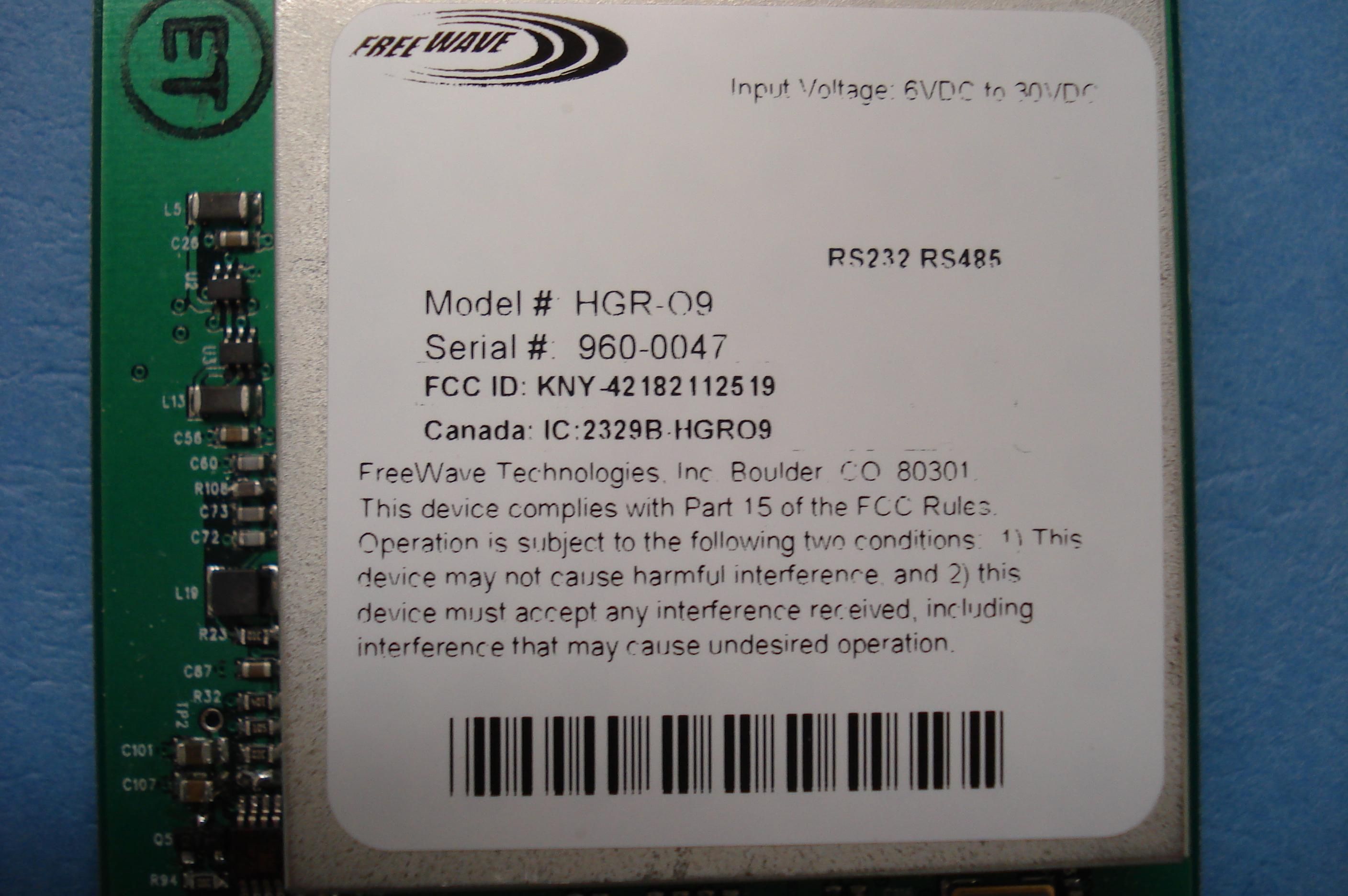
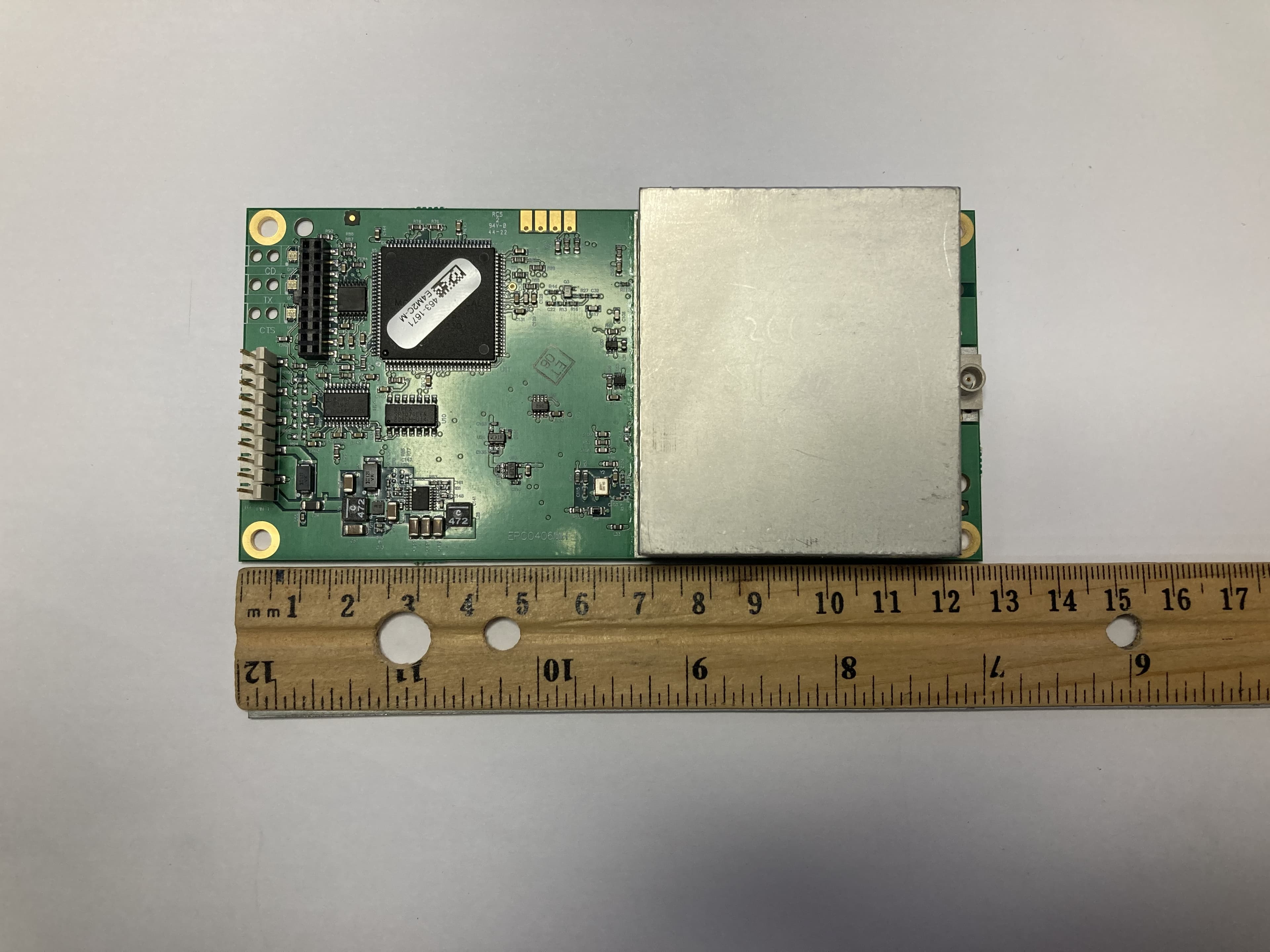
Photo: FGR2O9 Label Photo: FGR2O9 Transceiver Assembly Top w/ shield Photo: FGR2O9 Transceiver Assembly Top w/o Shield Photo: FGR2O9 Transceiver Assembly Bottom
ID Label/Location Info
Photo: FGR2O9 Label Photo: FGR2O9 Transceiver Assembly Top w/ shield
Internal Photos
Photo: FGR2O9 Label Photo: FGR2O9 Transceiver Assembly Top w/ shield Photo: FGR2O9 Transceiver Assembly Top w/o Shield Photo: FGR2O9 Transceiver Assembly Bottom
RF Exposure Info
November 27, 2007 FCC ID: KNY-42182112519 Maximum Permissible Exposure calculations To whom it may concern, FreeWave Technologies is submitting a low power output 902-928 MHz frequency DTS transceiver (FCC ID: KNY-42182112519). The MPE distance will be calculated for the worst case of a 100% transmitter duty cycle. For an isotropic radiator the surface area of a sphere can be used to determine the area over which the transceiver energy is radiated. Surface area of a sphere = 4 * π * radius 2 In the case where there is an antenna gain, the worst case energy density is increased by the antenna gain. In this case, the exposure level for a controlled environment can be calculated as follows: MPE distance =((output power*duty cycle*10*(antenna gain/10))/(4* π*Exposure Limit [mW/cm 2 ])) 1/2 In the case of 6 dBi antenna MPE distance = ((1000 mW * 1 * 3.98) /( 4 * 3.14 * 0.6)) 1/2 = 22.981 cm Sincerely, Rich Arment Engineering Technician
Test Report
Page 1 of 66 Engineering Test Report No. 39184-01 Measurement of RF Interference from a Model FGR2 Frequency Hoping Spread Spectrum Transceiver For : Free Wave Technologies Boulder CO 80301 P.O. No. : 26871 Date Tested : December 3 through January 29, 2007 Test Personnel : Richard King Specification : FCC "Code of Federal Regulations" Title 47 Part 15, Subpart C, Section 15.247 for Frequency Hopping Spread Spectrum Intentional Radiators Operating within the 902-928MHz band. RSS 210 Issue 7 June 2007 - Low-power Licence-exempt Radiocommunication Devices (All Frequency Bands) Test Report By : Richard King Approved By : Raymond J. Klouda Registered Professional Engineer of Illinois - 44894 Elite Electronic Engineering Inc. 1516 Centre Circle Downers Grove, IL 60515 Tel : (630) 495-9770 Fax: (630) 495-9785 www.elitetest.com Engineering Test Report No. 39184-01 THIS REPORT SHALL NOT BE REPRODUCED, EXCEPT IN FULL, WITHOUT THE WRITTEN APPROVAL OF ELITE ELECTRONIC ENGINEERING INCORPORATED. Page 2 of 66 TABLE OF CONTENTS PARAGRAPH DESCRIPTION OF CONTENTS PAGE NO. 1.0 INTRODUCTION .................................................................................................................................4 1.1 Description of Test Item....................................................................................................................4 1.2 Purpose ...........................................................................................................................................4 1.3 Deviations, Additions and Exclusions................................................................................................4 1.4 Applicable Documents......................................................................................................................4 1.5 Subcontractor Identification..............................................................................................................4 1.6 Laboratory Conditions .....................................................................................................................5 2.0 TEST ITEM SETUP AND OPERATION................................................................................................5 2.1 Power Input......................................................................................................................................5 2.2 Grounding........................................................................................................................................5 2.3 Peripheral Equipment.......................................................................................................................5 2.4 Interconnect Cables.........................................................................................................................5 2.5 Operational Mode.............................................................................................................................5 3.0 TEST EQUIPMENT..............................................................................................................................6 3.1 Test Equipment List..........................................................................................................................6 3.2 Calibration Traceability ...................................................................................................................6 4.0 REQUIREMENTS, PROCEDURES AND RESULTS ............................................................................6 4.1 Powerline Conducted Emissions ....................................................................................................6 4.2 Carrier Frequency Separation........................................................................................................7 4.3 Number of Hopping Frequencies ....................................................................................................7 4.4 Time of Occupancy ........................................................................................................................8 4.5 20dB Bandwidth ..............................................................................................................................8 4.6 Peak Output Power .........................................................................................................................9 4.7 Bandedge Compliance....................................................................................................................9 4.8 Duty Cycle.....................................................................................................................................10 4.9 Spurious Emissions ......................................................................................................................10 4.9.1 Antenna Conducted ...............................................................................................................10 4.9.2 Radiated Spurious Emissions ................................................................................................10 5.0 CONCLUSIONS.................................................................................................................................11 6.0 CERTIFICATION ...............................................................................................................................12 7.0 ENDORSEMENT DISCLAIMER.........................................................................................................12 TABLE I - EQUIPMENT LIST ......................................................................................................................... 11 Engineering Test Report No. 39184-01 Page 3 of 66 REVISION HISTORY Revision Date Description — Feb. 4, 2008 Initial release Engineering Test Report No. 39184-01 Page 4 of 66 Measurement of RF Emissions from a model FGR2 Transceiver 1.0 INTRODUCTION: 1.1 Description of Test Item - This document represents the results of the series of radio interferen…
Text truncated - open the document above for the full version.
Test Report
Page 1 of 64 Engineering Test Report No. 39186-01 Measurement of RF Interference from a Model FGR2 Wireless Digital Transmission Transceiver Using Digital Modulation For : Freewave Technologies Boulder, CO P.O. No. : 26871 Date Received : December 3, 2007 Date Tested : December 3 through January 29, 2008 Test Personnel : Richard E. King Specification : FCC "Code of Federal Regulations" Title 47 Part 15, Subpart C, Section 15.247 for Intentional Radiators Using Digital Modulation Operating within the 902MHz to 928MHz band. RSS 210 Issue 7 June 2007 - Low-power Licence-exempt Radiocommunication Devices (All Frequency Bands) Test Report By : Richard E. King Approved By : Raymond J. Klouda Registered Professional Engineer of Illinois - 44894 Elite Electronic Engineering Inc. 1516 Centre Circle Downers Grove, IL 60515 Tel : (630) 495-9770 Fax: (630) 495-9785 www.elitetest.com Engineering Test Report No. 39186-01 THIS REPORT SHALL NOT BE REPRODUCED, EXCEPT IN FULL, WITHOUT THE WRITTEN APPROVAL OF ELITE ELECTRONIC ENGINEERING INCORPORATED. Page 2 of 64 TABLE OF CONTENTS PARAGRAPH DESCRIPTION OF CONTENTS PAGE NO. 1.0 INTRODUCTION .................................................................................................................................4 1.1 Description of Test Item....................................................................................................................4 1.2 Purpose ...........................................................................................................................................4 1.3 Deviations, Additions and Exclusions................................................................................................4 1.4 Applicable Documents......................................................................................................................4 1.5 Subcontractor Identification..............................................................................................................4 1.6 Laboratory Conditions .....................................................................................................................5 2.0 TEST ITEM SETUP AND OPERATION................................................................................................5 2.1 Power Input......................................................................................................................................5 2.2 Grounding........................................................................................................................................5 2.3 Peripheral Equipment.......................................................................................................................5 2.4 Interconnect Cables.........................................................................................................................5 2.5 Operational Mode.............................................................................................................................5 3.0 TEST EQUIPMENT..............................................................................................................................5 3.1 Test Equipment List..........................................................................................................................5 3.2 Calibration Traceability ...................................................................................................................5 4.0 REQUIREMENTS, PROCEDURES AND RESULTS ............................................................................5 4.1 Powerline Conducted Emissions ....................................................................................................5 4.1.1 Requirements...........................................................................................................................5 5.1.2 Procedures...............................................................................................................................6 5.1.3 Results .....................................................................................................................................6 4.2 Antenna Conducted Emissions ................................................................…
Text truncated - open the document above for the full version.
Contact Information
Applicant
Richard Reisbick(VP Engineering)
Test Firm
Elite Electronic Engineering Inc.Kevin Halpin
Technical Specifications
| # | Rule Parts | Frequency Range | Power Output |
|---|---|---|---|
| 1 | 15C | 902.25 MHz - 927.82 MHz | 1 W |
Other Applications from FreeWave Technologies Inc.
KNYLRS455C
Oct 01, 2023LR455C
Equipment Class
TNB - Licensed Non-Broadcast Station Transmitter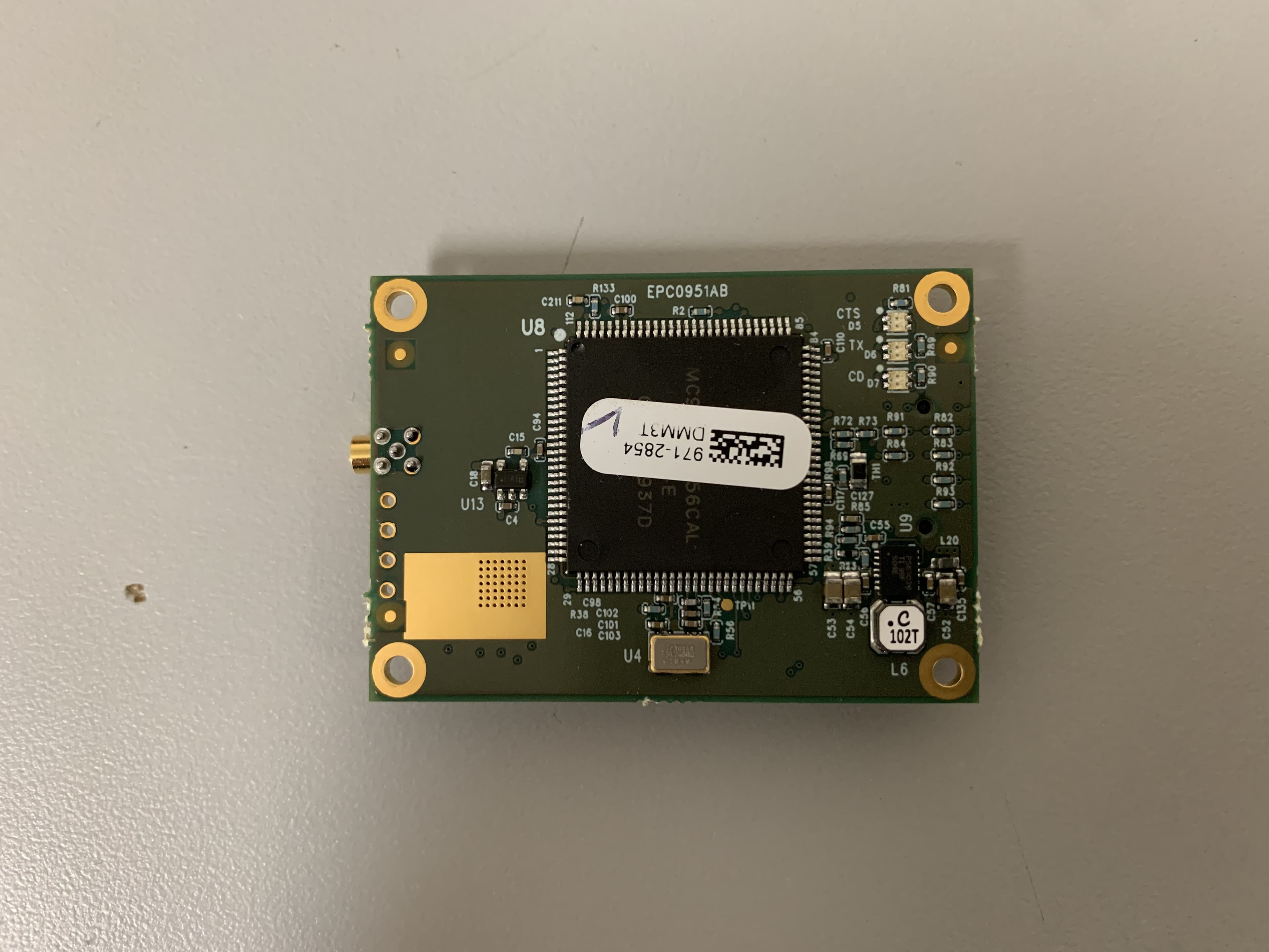
KNYMM3
Aug 25, 2020FHSS 902 - 928 MHz ISM band radio
Equipment Class
DSS - Part 15 Spread Spectrum Transmitter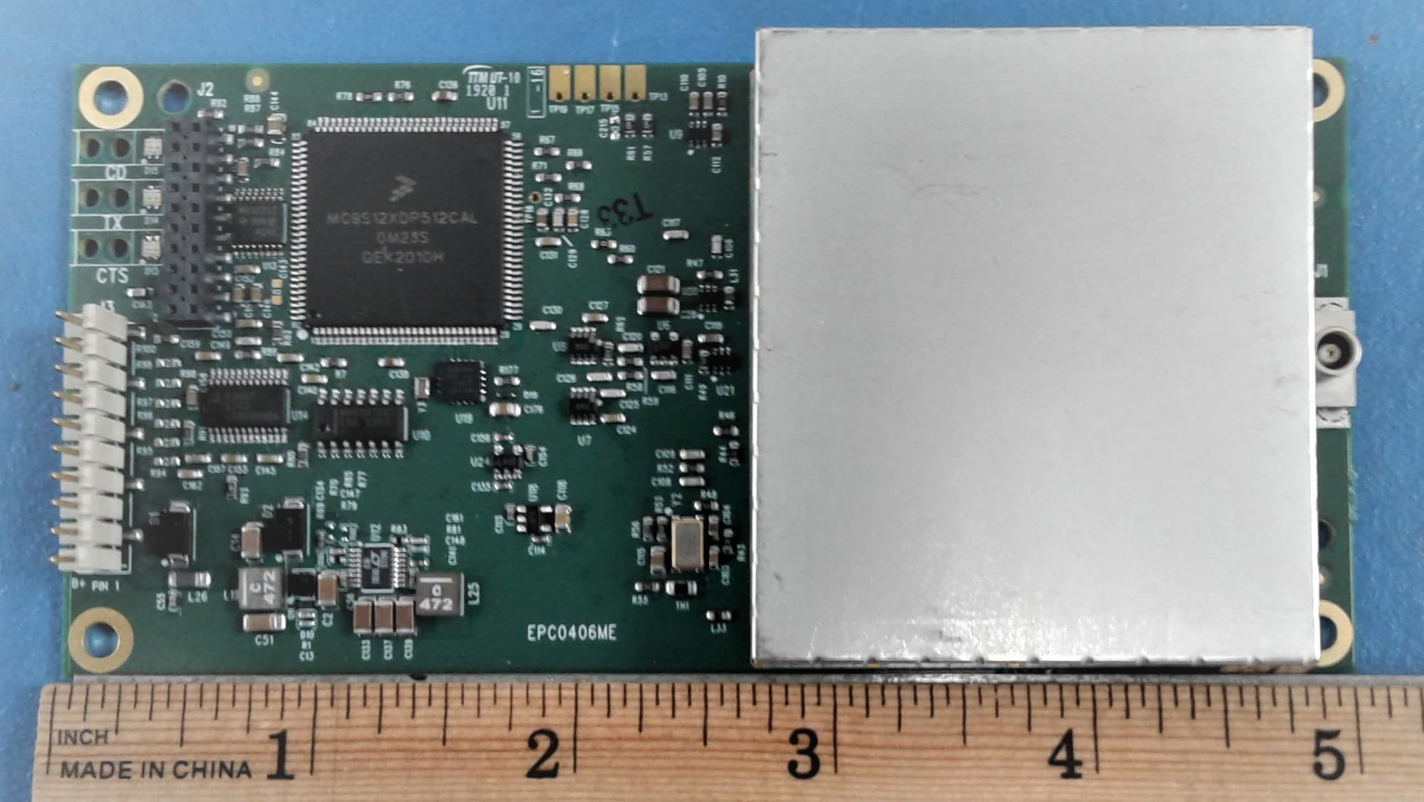
KNYLRS455A
Aug 04, 2020435-470 MHz Licensed Band Transceiver,
Equipment Class
TNB - Licensed Non-Broadcast Station Transmitter
KNYPRW5000AA
Oct 22, 2015Wireless 802.11ac/b/g/n access point
Equipment Class
DTS - Digital Transmission System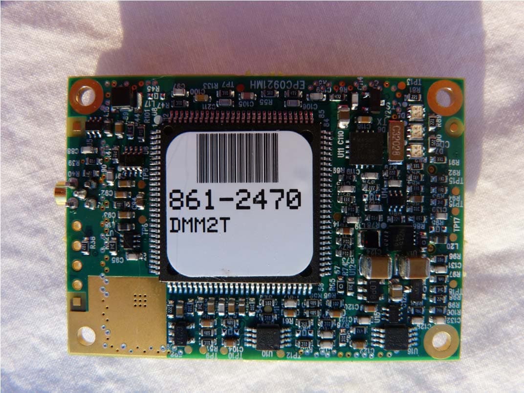
KNYAMM0921TT
Jan 14, 2014MM2
Equipment Class
DSS - Part 15 Spread Spectrum Transmitter