KNY-7157121521122.4 - 2.4835 GHz Wireless Data Transceiver
FreeWave Technologies Inc.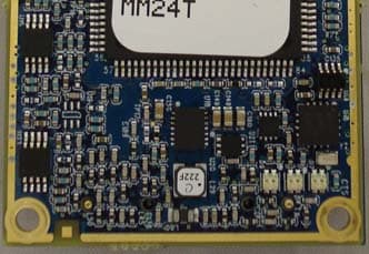
Click to zoom
Application Details
- Equipment Class
- DSS - Part 15 Spread Spectrum Transmitter
- Date of Grant
- May 03, 2011
- Application Purpose
- Original Equipment
- Date of Application
- Apr 28, 2011
- Equipment Note
- 2.4 - 2.4835 GHz Wireless Data Transceiver
- Frequency Range
- 2400.65280000 - 2483.48160000
- Company
- FreeWave Technologies Inc.
- Country
- United States
Documents & Files
Document Text
Text extracted from the exhibit documents filed with the FCC. Open a document above to read the original.
Users Manual
Global Transceiver Module (GXM) Wireless Data Transceiver User Manual Global Transceiver Module (GXM) Wireless Data Transceiver User Manual Version 1.0 FreeWave Technologies, Inc. 1880 South Flatiron Court Boulder, CO 80301 (303) 444-3862 (303) 786-9948 Fax www.FreeWave.com LUM0031AA Version 1.0 i Global Transceiver Module (GXM) Wireless Data Transceiver User Manual SPREAD SPECTRUM WIRELESS DATA TRANSCEIVER USER MANUAL W ARRANTY FreeWave Technologies warrants your FreeWave® Wireless Data Transceiver against defects in materials and manufacturing for a period of two years from the date of shipment. In the event of a Product failure due to materials or workmanship, FreeWave will, at its option, repair or replace the Product. The Product must be returned to FreeWave upon receiving a Return Material Authorization (RMA) for evaluation of Warranty Coverage. In no event will FreeWave Technologies Inc., its suppliers, and its licensors be liable for any damages arising from the use of or inability to use this Product. This includes business interruption, loss of business information, or other loss which may arise from the use of this Product. Please be advised that OEM customer’s warranty periods may vary. Warranty Policy may not apply: 1. If Product repair, adjustments or parts replacements is required due to accident, neglect, unusual physical, electrical or electromagnetic stress. 2. If Product is used outside of FreeWave specifications. 3. If Product has been modified, repaired or altered by Customer unless FreeWave specifically authorized such alterations in each instance in writing. This includes the addition of conformal coating. Special Rate Replacement Option A special rate replacement option is offered to non-warranty returns or upgrades. The option to purchase the replacement unit at this special rate is only valid for that RMA. The special replacement rate option expires if not exercised within 30 days of final disposition of RMA. R ESTRICTED RIGHTS Any product names mentioned in this manual may be trademarks or registered trademarks of their respective companies and are hereby acknowledged. Information in this manual is subject to change without notice and is proprietary and confidential to FreeWave Technologies, Inc. This manual is for use by purchasers and other authorized users of the FreeWave® Wireless Data Transceiver only. No part of this manual may be reproduced or transmitted in any form or by any means, electronic or mechanical, or for any purpose without the express written permission of FreeWave Technologies, Inc. FreeWave Spread Spectrum Wireless Data Transceivers are designed and manufactured in the United States of America. Printed in the United States of America. Copyright © 2011 by FreeWave Technologies, Inc. All rights reserved. Published 2011. LUM0031AA Version 1.0 ii FreeWave Technologies, Inc. 1180 S Flatiron Ct Ste F Boulder, CO 80501 (303) 381-9200 Global Transceiver Module (GXM) Wireless Data Transceiver User Manual This product is licensed by The United States. Diversion contrary to U.S. law is prohibited. Shipment or re-export of this product outside of The United States may require authorization by the U.S. Bureau of Export Administration. Please contact FreeWave Technologies for assistance and further information. UL NOTIFICATION Models GXM-T14, GXM-T24, GX-C, GX-T, GXM-MR-T, GXM-MR-R are suitable for use in Class 1, Division 2, Groups A, B, C, and D or non-hazardous locations only. Input voltage for the above models is 3.3 – 5 volts DC. FCC NOTIFICATIONS This device complies with part 15 of the FCC rules. Operation is subject to the following two conditions: 1) This device may not cause harmful interference and 2) this device must accept any interference received, including interference that may cause undesired operation. This device must be operated as supplied by FreeWave Technologies, Inc. Any changes or modifications made to the device without the express written approval of FreeWave Technologies may void the user's authority to operate the device. CAUTION: The GXM transceivers have a maximum transmitted output power of 500mW. It is recommended that the transmit antenna be kept at least 20 cm away from nearby persons to satisfy FCC RF exposure requirements. This equipment has been tested and found to comply with the limits for a Class B digital device, pursuant to part 15 of the FCC Rules. These limits are designed to provide reasonable protection against harmful interference in a residential installation. This equipment generates, uses, and can radiate radio frequency energy and, if not installed and used in accordance with the instructions, may cause harmful interference to radio communications. However, no guarantee shall be made that interference will not occur in a particular installation. If this equipment does cause harmful interference to radio or television reception, which can be determined by turning the equipment off and on, the user is encouraged to try to correct the interference by one or more of the following measures: Reorient or relocate the receiving antenna. Increase the separation between the equipment and receiver. Connect the equipment into an outlet on a circuit different from that to which the receiver is connected. Consult the dealer or an experienced radio/TV technician for help. Note: Whenever any FreeWave Technologies module is placed inside an enclosure a label must be placed on the outside of that enclosure which includes the module's FCC ID. IC NOTIFICATIONS This device complies with Industry Canada licence-exempt RSS standard(s). Operation is subject to the following two conditions: (1) this device may not cause interference, and (2) this device must accept any interference, including interference that may cause undesired operation of the device. Ce dispositif est conforme aux normes permis-exemptes du Canada RSS d'industrie. L'opération est sujette aux deux conditions suivantes : (1) ce dispositif peut ne pas …
Text truncated - open the document above for the full version.
Cover Letter(s)
April 4, 2011 Attn: Director of Certification Re: FCC ID: KNY-715712152112 Request Modular Authority We (FreeWave Technologies Inc.) hereby request Modular Approval based on the numbered requirements identified below as we address them to be included in our application for equipment authorization. 1. The modular transmitter must have its own RF shielding. This is intended to ensure that the module does not have to rely upon the shielding provided by the device into which it is installed in order for all modular transmitter emissions to comply with Part 15 limits. It is also intended to prevent coupling between the RF circuitry of the module and any wires or circuits in the device into which the module is installed. Such coupling may result in non-compliant operation. Our equipment provides RF shield over the whole RF/analog section as well as additional shield over RF VCO area. 2. The modular transmitter must have buffered modulation/data inputs (if such inputs are provided) to ensure that the module will comply with Part 15 requirements under conditions of excessive data rates or over-modulation. Our equipment buffers TTL data inputs in microcontroller. Microcontroller independently sets over the air data rates and TX deviation 3. The modular transmitter must have its own power supply regulation. This is intended to ensure that the module will comply with Part 15 requirements regardless of the design of the power supplying circuitry in the device into which the module is installed. Our equipment meets this by providing on-board buck-boost switching regulator that assures constant output voltage within specified Vin variation (3.3V-5V ±10%) 4. The modular transmitter must comply with the antenna requirements of Section 15.203 and 15.204(c). The antenna must either be permanently attached or employ a “unique” antenna coupler (at all connections between the module and the antenna, including the cable). Any antenna used with the module must be approved with the module, either at the time of initial authorization or through a Class II permissive change. The “professional installation” provision of Section 15.203 may not be applied to modules. Our equipment meets this by providing MMCX connector and requiring professional installation. 5. The modular transmitter must be tested in a stand-alone configuration, i.e., the module must not be inside another device during testing. This is intended to demonstrate that the module is capable of complying with Part 15 emission limits regardless of the device into which it is eventually installed. Unless the transmitter module will be battery powered, it must comply with the AC line conducted requirements found in Section 15.207. AC or DC power lines and data input/output lines connected to the module must not contain ferrites, unless they will be marketed with the module (see Section 15.27(a)). The length of these lines shall be length typical of actual use or, if that length is unknown, at least 10 centimeters to insure that there is no coupling between the case of the module and supporting equipment. Any accessories, peripherals, or support equipment connected to the module during testing shall be unmodified or commercially available (see Section 15.31(i)). Our equipment was tested in stand-alone mode with external supply connected to radio module. It was found compliant with Section 15.207 requirements. 6. The modular transmitter must be labeled with its own FCC ID number, and, if the FCC ID is not visible when the module is installed inside another device, then the outside of the device into which the module is installed must also display a label referring to the enclosed module. This exterior label can use wording such as the following: “Contains Transmitter Module FCC ID: XYZMODEL1” or “Contains FCC ID: XYZMODEL1.” Any similar wording that expresses the same meaning may be used. The Grantee may either provide such a label, an example of which must be included in the application for equipment authorization, or, must provide adequate instructions along with the module which explain this requirement. In the latter case, a copy of these instructions must be included in the application for equipment authorization. Our equipment meets this by providing label with FCC ID clearly visible on every unit. 7. The modular transmitter must comply with any specific rule or operating requirements applicable to the transmitter and the manufacturer must provide adequate instructions along with the module to explain any such requirements. A copy of these instructions must be included in the application for equipment authorization. For example, there are very strict operational and timing requirements that must be met before a transmitter is authorized for operation under Section 15.231. For instance, data transmission is prohibited, except for operation under Section 15.231(e), in which case there are separate field strength level and timing requirements. Compliance with these requirements must be assured. Our equipment meets this by limiting operating frequency and Output RF power by internal FW setting. We also provide operating manuals in printed form and on soft media. 8. The modular transmitter must comply with any applicable RF exposure requirements. For example, FCC Rules in Sections 2.1091, 2.1093 and specific Sections of Part 15, including 15.319(i), 15.407(f), 15.253(f) and 15.255(g), require that Unlicensed PCS, UNII and millimeter wave devices perform routine environmental evaluation for RF Exposure to demonstrate compliance. In addition, spread spectrum transmitters operating under Section 15.247 are required to address RF Exposure compliance in accordance with Section 15.247(b)(4). Modular transmitters approved under other Sections of Part 15, when necessary, may also need to address certain RF Exposure concerns, typically by providing specific installation and operating instructions for users, installers and other interested parties to ensure complian…
Text truncated - open the document above for the full version.
Cover Letter(s)
Authority to Act as Agent Date: February 10, 2011 American Certification Body, Inc. 6731 Whittier Avenue Suite C110 McLean, VA 22101 To Whom It May Concern: EMC Integrity is authorized to act on our behalf, until otherwise notified, for applications to American Certification Body, Inc. (ACB). We certify that we are not subject to denial of federal benefits, that includes FCC benefits, pursuant to Section 5301 of the Anti-Drug Abuse Act of 1988, 21 U.S.C. 862. Further, no party, as defined in 47 CFR 1.2002 (b), to the application is subject to denial of federal benefits, that includes FCC benefits. Thank you, Agency Agreement Expiration Date: February 1, 2012 By: Rich Arment (Signature) (Print name) Title: Regulatory Compliance Leader On behalf of: FreeWave Technologies Inc. (Company Name) Telephone: 303-444-3862
Cover Letter(s)
Request for Confidentiality Date: March 25, 2011 Subject: Confidentiality Request for: FCC ID: KNY-715712152112 IC ID: IC-2329B-GXM24 Pursuant to FCC 47 CRF 0.457(d) and 0.459 and IC RSP-100, Section 10, the applicant requests that a part of the subject FCC application be held confidential. Type of Confidentiality Requested Exhibit Short Term Permanent Block Diagrams Short Term External Photos Short Term Permanent* Internal Photos Short Term Permanent Operation Description/Theory of Operation Short Term Permanent Parts List & Placement/BOM Short Term Permanent Tune-Up Procedure Short Term Permanent Schematics Short Term Test Setup Photos Short Term Permanent* User’s Manual FreeWave Technologies Inc. has spent substantial effort in developing this product and it is one of the first of its kind in industry. Having the subject information easily available to "competition" would negate the advantage they have achieved by developing this product. Not protecting the details of the design will result in financial hardship. Permanent Confidentiality: The applicant requests the exhibits listed above as permanently confidential be permanently withheld from public review due to materials that contain trade secrets and proprietary information not customarily released to the public. Short-Term Confidentiality: The applicant requests the exhibits selected above as short term confidential be withheld from public view for a period of N/A days from the date of the Grant of Equipment Authorization and prior to marketing. This is to avoid premature release of sensitive information prior to marketing or release of the product to the public. Applicant is also aware that they are responsible to notify ACB in the event information regarding the product or the product is made available to the public. ACB will then release the documents listed above for public disclosure pursuant to FCC Public Notice DA 04-1705. NOTE for Industry Canada Applications: The applicant understands that until such time that IC distinguishes between Short Term and Permanent Confidentiality, either type of marked exhibit above will simply be marked Confidential when submitted to IC. Sincerely, By: Regulatory Compliance Leader Rich Arment (Signature/Title) (Print name)
Cover Letter(s)
April 28 th , 2011 RE: ATCB010302 – Original Equipment & New Family Certification Applications – (Models: GXM-T14, GXM-T24, GX-C, GX-T, GXM-MR-R, GXM-MR-T & GX-CP) FCC ID: KNY-715712152112 & IC: 2329B-GXM-24 for Freewave Technologies, Inc. 1.) Reply to ATCB comment #1: Reply, Freewave 04-11-11. The GX family of products starts with the GXM-T14 or GXM-T24 Radio. These devices are rated at 3.3-5VDC and are aimed at OEM markets. The difference only between these two radios is the interface connector. The GXM-T14 has a 14-pin interface connector, while the GXM-T24 has a 24-pin interface connector. The 14-pin connector provides Power and TTL data connections (in an RS-232 format) to the radio. The 24-pin and adds a diagnostic port and other control lines that are utilized by the GXCP. The GX-C and GX-T are board level devices that utilize a 6-30VDC input and have (on the GX–C) an RS-232/ RS-422/RS-485 switchable interface, or (on the GX–T) a TTL interface. The two devices consist of the GXM-T24 and a “full size” interface board (136mm L x 62mmW). The footprint matches previous FreeWave radio footprints for customers wanting to replace legacy products with this new generation of products. The GXM-MR-R and GXM-MR-T are very similar to the GX-C and GX-T in that they incorporate the use of an interface board. This interface is a ½ size board, however. (73mm L x 62mm W) The GXM-MR radios utilize a 6-30VDC input and allow a TTL data interface on the GX-MR-T. The GX-MR-R is limited to an RS-232 interface instead of the “combined” option of the GX-C. The GXCP device consists of a GX-T mated to a FreeWave Cathodic Protection daughter board. The Cathodic Protection board is utilized by customers who need to monitor information dealing with pipe corrosion and other issues. 12.) Reply to ATCB comment # 12: Reply, EMC Integrity, 04-21-11. Device was tested according to ANSI C63.10-2009 and FCC Public Notice DA 00-705, “Filing and Measurement Guidelines for Frequency Hopping Spread Spectrum Systems”. Test reports have been amended to reflect this. Please see attached PDF file, ETRB10102_IC_RevA 13.) Reply to ATCB comment # 13: Reply, Freewave, 04-11-11. The RF device is IDENTICAL in all models. The only thing different in most models is the interface board and whether it is RS-232 or TTL. The Data Rate at which the radio was tested is the fastest that the radio is capable. The hopping sequence’s have no bearing on the output power, especially since the majority of the tests were done in single frequency mode. 14.) Reply to ATCB comment # 14: Reply, Freewave, 04-11-11. This is correct. The way the manual is written shows the frequencies with the Frequency Offset of 0 set. If the chart showed the Frequency Offset as set to 2, the low end would not match. I did make a change to reflect the correct frequencies but other than that, we are not changing the chart in the manual. Nor adding another chart. 17.) Reply to ATCB comment # 17: Reply, EMC Integrity, 04-21-11. Yes, the losses in the attenuator and connecting cable were accounted for in the spectrum analyzer readings. The losses were entered as an amplitude offset in the analyzer, so the readings shown on the analyzer screen reflect the actual output power at the transmitter’s antenna connector. The amended reports include a statement that this is the case. Please see attached PDF files, ETRB10102_IC_RevA and ETRB10102_FCC_RevA 20.) Reply to ATCB comment # 20: Reply, EMC Integrity, 04-21-11, Please see attached PDF files, ETRB10102_IC_RevA and ETRB10102_FCC_RevA (a) Reply, EMC Integrity, 04-21-11, There is one radiated emissions test result (graph & table) below 1 GHz. It was tested with the transceiver on (Tx + Rx, mid-band) and these are the same results listed in the Receiver Spurious Emissions section. (b) Reply, EMC Integrity, 04-21-11, ≤ 1 GHz, d=10m, > 1 GHz, d=3m (d) Reply, EMC Integrity, 04-21-11, These are plots of the Prescan results, and Prescans are performed with the peak detector, using the following bandwidth settings: ≤ 1 GHz: RBW = 1 MHz, VBW = 3 MHz > 1 GHz: RBW = 1 MHz, VBW = 3 MHz As these bandwidths are wider than those used for the final QP (RBW=120kHz) or Avg (VBW=10Hz) readings, these Prescan graphs represent signals that are higher (or equal to) the levels that would be measured with an QP or Average detector. If these peak- detected Prescan results (using wider bandwidths) are compliant, then the QP and Avg results will be as well (and likely would exhibit even larger margins). (f) Reply, EMC Integrity, 04-21-11, Yes. This would be evident if there were data tables associated with these graphs. Amended report has been modified to reflect this.
Internal Photos
The GX family of products starts with the GXM-T14 or GXM-T24 Radio. These devices are rated at 3.3-5VDC and are aimed at OEM markets. The only difference between these two radios is the interface connector. The GXM-T14 has a 14-pin interface connector, while the GXM-T24 has a 24-pin interface connector. The 14-pin connector provides Power and TTL data connections (in an RS-232 format) to the radio. The 24-pin and adds a diagnostic port and other control lines. GXM-14 Top and Bottom (14-pin interface connector, 3.3-5VDC) GXM-24 Top and Bottom (24-pin interface connector, 3.3-5VDC) The GX-C and GX-T are board level devices that utilize a 6-30VDC input and have (on the GX–C) an RS-232/ RS-422/RS-485 switchable interface, or (on the GX–T) a TTL interface. The two devices consist of the GXM-T24 and a “full size” interface board (136mm L x 62mmW). The footprint matches previous FreeWave radio footprints for customers wanting to replace legacy products with this new generation of products. GX-C Top & Bottom (RS-232/422/485, 6-30VDC) GX-T Top & Bottom (TTL, 6-30VDC) GXM module with RF Shield removed. The GXM-MR-R and GXM-MR-T are very similar to the GX-C and GX-T in that they incorporate the use of an interface board. This interface is a ½ size board, however. (73mm L x 62mm W) The GXM-MR radios utilize a 6-30VDC input and allow a TTL data interface on the GX-MR-T. The GX-MR-R is limited to an RS-232 interface instead of the “combined” option of the GX-C. The MR interface boards mate to the GXM-T14 to create the GXM-MR-R and GXM-MR-T. GXM-MR-R Top and Bottom (RS-232, 6-30VDC) GXM-MR-T Top & Bottom (TTL, 6-30VDC) The GXCP device consists of a GX-T mated to a FreeWave Cathodic Protection daughter board. The Cathodic Protection board is utilized by customers who need to monitor information dealing with pipe corrosion and other issues.
Test Report
EMC Integrity Test Report: ETRB10102_FCC_RevB Applicant: FreeWave Technologies, Inc. 1880 S. Flatiron Court Suite F Boulder, CO 80301 Equipment Under Test: GX-CP (E.U.T.) 2.4-2.4835GHz FHSS Transceiver, 6-30VDC w/ CP board In Accordance With: FCC Part 15.247 Frequency Hopping Spread Spectrum Transmitter Tested By: EMC Integrity, Inc. 1736 Vista View Drive Longmont, CO 80504 TESTED BY: Brian Annis DATE: 06-May-2011 APPROVED BY: Vincent Greb DATE: 06-May-2011 Number of Pages: 40 EMC Integrity, Inc. FCC PART 15.247 EUT: Freewave GX-CP Frequency Hopping Spread Spectrum FCC ID: KNY-715712152112 Test Report No.: ETRB10102_FCC_RevB Page 2 of 40 Table of Contents SECTION 2. EQUIPMENT UNDER TEST (E.U.T.) 5 SECTION 3. CHANNEL SEPARATION & OCCUPIED BANDWIDTH 6 SECTION 4. MAXIMUM PEAK OUTPUT POWER 9 SECTION 5. CHANNEL DWELL TIME 12 SECTION 6. NUMBER OF CHANNELS 14 SECTION 7. SPURIOUS EMISSIONS AT ANTENNA TERMINALS 15 SECTION 8. RADIATED EMISSIONS (RESTRICTED BAND) 20 SECTION 9. POWERLINE CONDUCTED EMISSIONS 24 SECTION 10. TEST EQUIPMENT LIST 29 ANNEX A - TEST DETAILS 30 ANNEX B - TEST DIAGRAMS 38 EMC Integrity, Inc. FCC PART 15.247 EUT: Freewave GX-CP Frequency Hopping Spread Spectrum FCC ID: KNY-715712152112 Test Report No.: ETRB10102_FCC_RevB Page 3 of 40 Section 1. Summary of Test Results Manufacturer: FreeWave Technologies, Inc. Model No.: GX-CP Serial No.: 244-1885 General: All measurements are traceable to national standards. These tests were conducted on a sample of the equipment for the purpose of demonstrating compliance with Part 15, Subpart C, Paragraph 15.247 and RSS-GEN, Issue 3 for Frequency Hopping Spread Spectrum Systems. Radiated tests were conducted in accordance with ANSI C63.4-2003. Radiated emissions are made on a listed test site. A description of the test facility is on file with the FCC and Industry Canada. New Submission Production Unit Class II Permissive Change Pre-Production Unit THIS TEST REPORT RELATES ONLY TO THE ITEM(S) TESTED. EMC Integrity Inc. authorizes the above named company to reproduce this report provided it is reproduced in its entirety and for use by the company’s employees only. Any use which a third party makes of this report, or any reliance on or decisions to be made based on it, are the responsibility of such third parties. EMC Integrity Inc. accepts no responsibility for damages, if any, suffered by any third party as a result of decisions made or actions based on this report. This report applies only to the items tested. EMC Integrity, Inc. FCC PART 15.247 EUT: Freewave GX-CP Frequency Hopping Spread Spectrum FCC ID: KNY-715712152112 Test Report No.: ETRB10102_FCC_RevB Page 4 of 40 Summary Of Test Data NAME OF TEST PARA. NO. RESULT Channel Separation FCC 15.247(a)(1) Complies Occupied Bandwidth FCC 15.247(a)(1) Complies Maximum Peak Power Output FCC 15.247(b)(1) Complies Channel Dwell Time FCC 15.247(a)(1)(iii) Complies Number of Channels FCC 15.247(a)(1)(iii) Complies Spurious Emissions (Antenna Conducted) FCC 15.247(d) Complies Radiated Emissions (Restricted Bands) FCC 15.247(d) Complies Powerline Conducted Emissions FCC 15.207 Complies Description of DUT: 2.4-2.4835GHz, 115K Over-the-Air Data Rate, frequency-hopping spread-spectrum wireless data transceiver, board level, 6-30 volts DC power input, RS-232/485/422. Max RF power output 500 mW. Modulation type is 2-level GFSK. Device was tested with two different antennas. Industrial usage: oil fields, agriculture, etc. Dimensions 127 L x 61 W x 15 H (mm), weight 53g. EMC Integrity, Inc. FCC PART 15.247 EUT: Freewave GX-CP Frequency Hopping Spread Spectrum FCC ID: KNY-715712152112 Test Report No.: ETRB10102_FCC_RevB Page 5 of 40 Section 2. Equipment Under Test (E.U.T.) General Equipment Information Frequency Band (MHz): 902-928 2400-2483.5 5725-5850 Operating Frequency of Test Sample: 2.4-2.4835 GHz Channel Spacing: 1 MHz User Frequency Adjustment: Menu-based (limited frequency set) EMC Integrity, Inc. FCC PART 15.247 EUT: Freewave GX-CP Frequency Hopping Spread Spectrum FCC ID: KNY-715712152112 Test Report No.: ETRB10102_FCC_RevB Page 6 of 40 Section 3. Channel Separation & Occupied Bandwidth NAME OF TEST: Channel Separation & Occupied Bandwidth PARA. NO.: 15.247(a)(1) TESTED BY: Brian Annis DATE: 4 Jan 2011 Test Results: Complies. Measurement Data: See 20B BW plot Measured 20B bandwidth: 250 kHz Channel Separation 1 MHz Test Conditions: 18 %RH 22 °C Measurement Uncertainty: +/-1x10 -7 ppm Test Equipment Used: 1215, 20 dB atten EMC Integrity, Inc. FCC PART 15.247 EUT: Freewave GX-CP Frequency Hopping Spread Spectrum FCC ID: KNY-715712152112 Test Report No.: ETRB10102_FCC_RevB Page 7 of 40 Test Data – Occupied Bandwidth EMC Integrity, Inc. FCC PART 15.247 EUT: Freewave GX-CP Frequency Hopping Spread Spectrum FCC ID: KNY-715712152112 Test Report No.: ETRB10102_FCC_RevB Page 8 of 40 Test Data – Occupied Bandwidth EMC Integrity, Inc. FCC PART 15.247 EUT: Freewave GX-CP Frequency Hopping Spread Spectrum FCC ID: KNY-715712152112 Test Report No.: ETRB10102_FCC_RevB Page 9 of 40 Section 4. Maximum Peak Output Power NAME OF TEST: Maximum Peak Output power PARA. NO.: 15.247(b)(1) TESTED BY: Brian Annis DATE: 06-May-2011 Test Results: Complies. Highest measured peak power was +27.00 dBm (500 mW) Measurement Data: Refer to attached data Test Conditions: 21 %RH 20 °C Measurement Uncertainty: +/-1.7 dB Test Equipment Used: 1215, 20 dB atten Notes: The readings shown in the following spectrum analyzer screencaps have already been corrected for the losses in the interconnecting cable and attenuator, and reflect the true measured output power at the antenna terminals of the transmitter. This device was tested at +/- 15% input power per 15.31(e), with no variation in output power. The device was tested on three channels per 15.31(m). EMC Integrity, Inc. FCC PART 15.247 EUT: Freewave GX-CP Frequency Hopping Spread Spectrum FCC ID: KNY-715712152112 Test Report No.: ETRB10102_FCC_RevB Page 10 of 40 Test Data – Peak Power…
Text truncated - open the document above for the full version.
Contact Information
Applicant
Richard Reisbick(VP Engineering)
Test Firm
EMC Integrity, Inc.Mike Wolf
Technical Specifications
| # | Rule Parts | Frequency Range | Power Output |
|---|---|---|---|
| 1 | 15C | 2.40 GHz - 2.48 GHz | 500.00 mW |
Other Applications from FreeWave Technologies Inc.
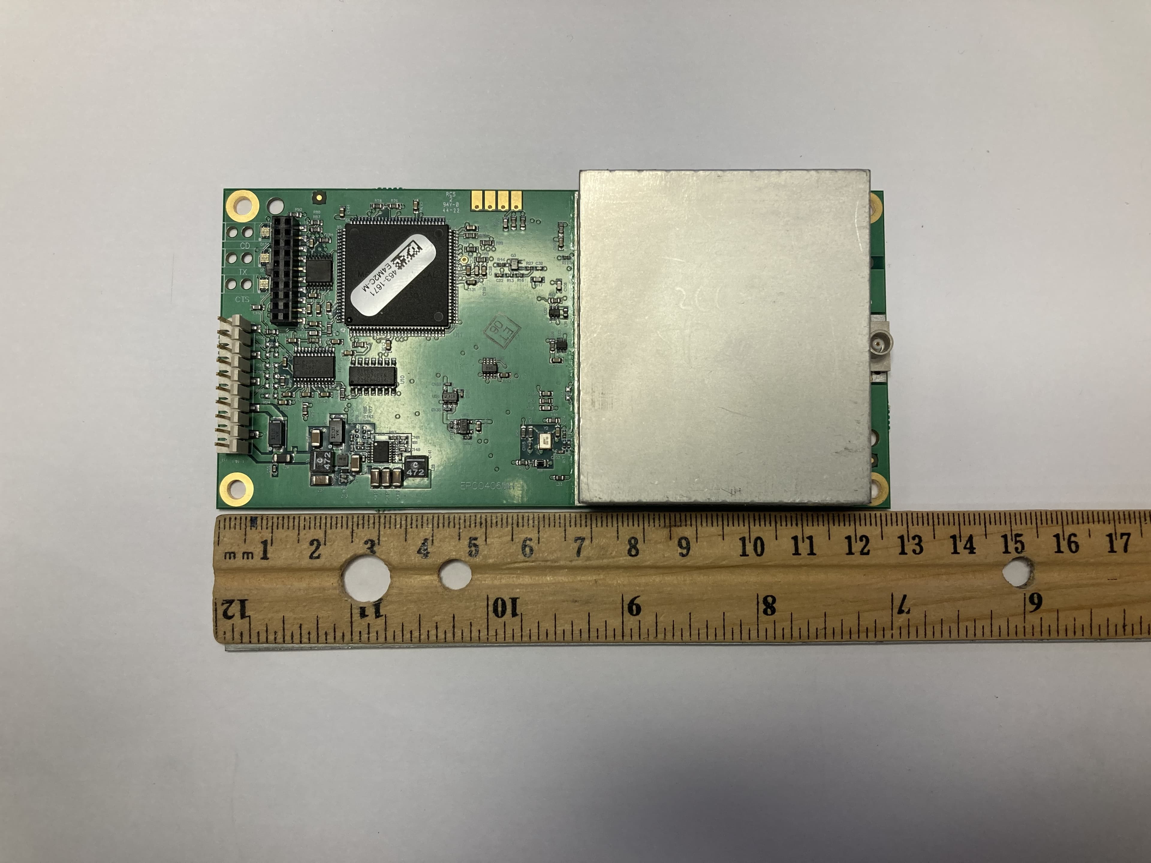
KNYLRS455C
Oct 01, 2023LR455C
Equipment Class
TNB - Licensed Non-Broadcast Station Transmitter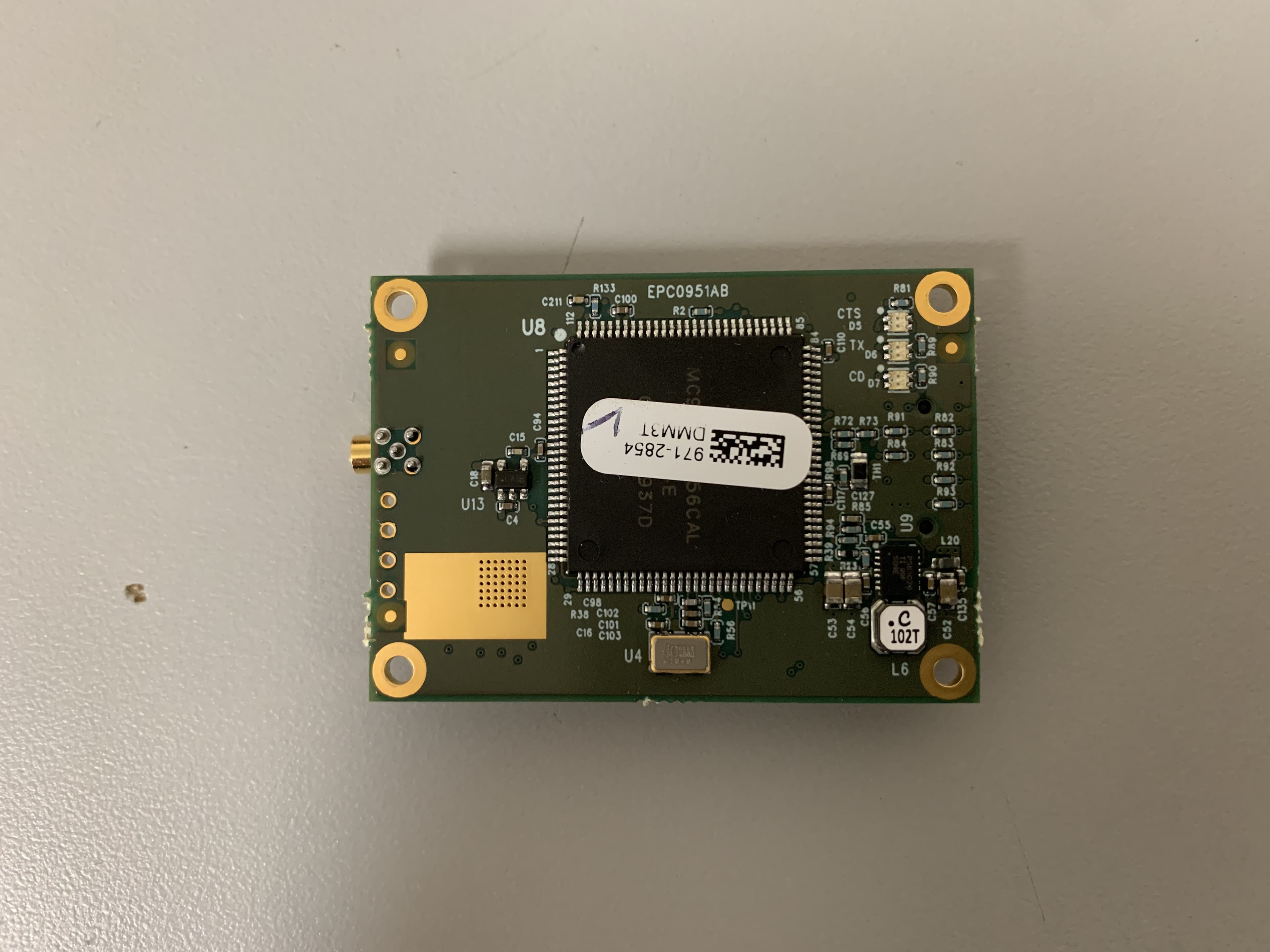
KNYMM3
Aug 25, 2020FHSS 902 - 928 MHz ISM band radio
Equipment Class
DSS - Part 15 Spread Spectrum Transmitter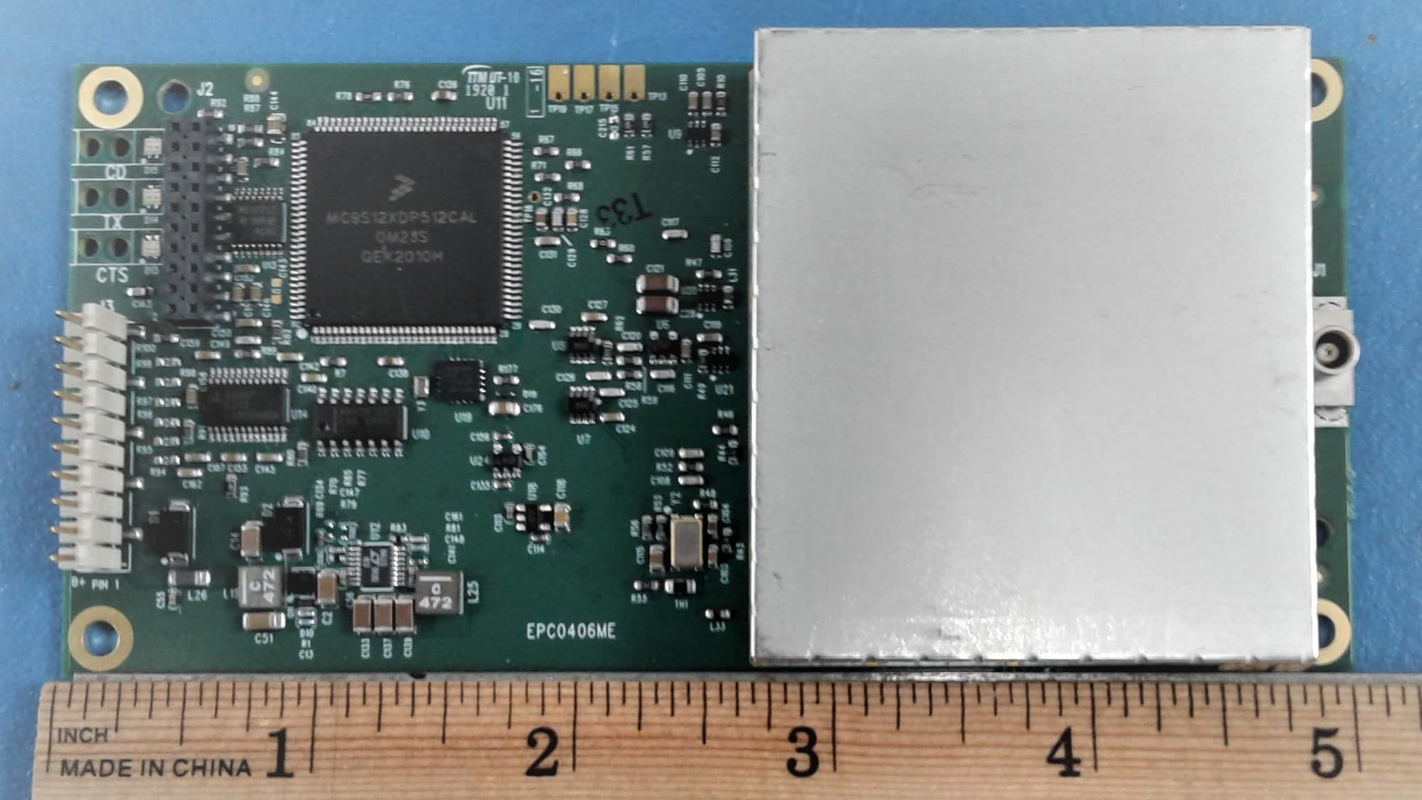
KNYLRS455A
Aug 04, 2020435-470 MHz Licensed Band Transceiver,
Equipment Class
TNB - Licensed Non-Broadcast Station Transmitter
KNYPRW5000AA
Oct 22, 2015Wireless 802.11ac/b/g/n access point
Equipment Class
DTS - Digital Transmission System
KNYAMM0921TT
Jan 14, 2014MM2
Equipment Class
DSS - Part 15 Spread Spectrum Transmitter