KNY29205135134192.4 GHz Wireless Data Transceiver
FreeWave Technologies Inc.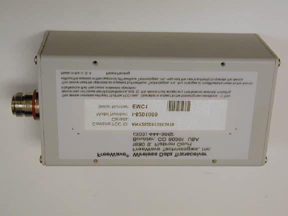
Click to zoom
Application Details
- Equipment Class
- DSS - Part 15 Spread Spectrum Transmitter
- Date of Grant
- Nov 21, 2002
- Application Purpose
- Original Equipment
- Date of Application
- Nov 21, 2002
- Equipment Note
- 2.4 GHz Wireless Data Transceiver
- Frequency Range
- 2400.00000000 - 2483.50000000
- Company
- FreeWave Technologies Inc.
- Country
- United States
Documents & Files
Document Text
Text extracted from the exhibit documents filed with the FCC. Open a document above to read the original.
Users Manual
FreeWave Spread Spectrum Wireless Data Transceiver User Manual FreeWave Technologies, Inc. 1880 South Flatiron Court Boulder, CO 80301 USA (303) 444-3862 (303) 786-9948 Fax www.freewave.com FreeWave Technologies Spread Spectrum Transceiver User Manual 900 MHz and 2.4 GHz V5.0S i This manual is for use by purchasers and other authorized users of the FreeWave™ Wireless Data Transceiver only. No part of this document may be reproduced or transmitted in any form or by any means, electronic or mechanical, or for any purpose without the express written permission of FreeWave Technologies, Inc. Warranty Your FreeWave Wireless Data Transceiver is warranted against defects in materials and manufacturing for a period of two years from the date of purchase. In the event of a product failure due to materials or workmanship, FreeWave Technologies will, at its discretion, repair or replace the product. FreeWave Technologies, its suppliers, and its licensors shall in no event be liable for any damages arising from the use of or inability to use this product. This includes business interruption, loss of business information, or other loss which may arise from the use of this product. Information in this document is subject to change without notice. © 1995-2002 FreeWave Technologies, Inc. All rights reserved. Microsoft and Windows are registered trademarks of the Microsoft Corporation. pcANYWHERE is a registered trademark of Symantec Corporation. Other product names mentioned in this manual may be copyrights, trademarks, or registered trademarks of their respective companies and are hereby acknowledged. The FreeWave Wireless Data Transceiver is made in the United States of America. Printed in the United States of America. FreeWave Technologies Spread Spectrum Transceiver User Manual 900 MHz and 2.4 GHz V5.0S ii FreeWave Technologies Spread Spectrum Transceiver User Manual 900 MHz and 2.4 GHz V5.0S iii FCC Notification This device complies with part 15 of the FCC rules. Operation is subject to the following two conditions: 1) This device may not cause harmful interference and 2) this device must accept any interference received, including interference that may cause undesired operation. This device must be operated as supplied by FreeWave Technologies, Inc. Any changes or modifications made to the device without the express written approval of FreeWave Technologies may void the user's authority to operate the device. CAUTION: The model number FGR09 has a maximum transmitted output power of 955mW. It is required that the transmit antenna be kept at least 23 cm away from nearby persons to satisfy FCC RF exposure requirements. The “I”-series radio transceivers have maximum transmitted output power of 500 mW. It is required that the transmit antenna be kept at least 36 cm away from nearby persons to satisfy FCC RF exposure requirements. Note: This equipment has been tested and found to comply with the limits for a Class B digital device, pursuant to part 15 of the FCC Rules. These limits are designed to provide reasonable protection against harmful interference in a residential installation. This equipment generates, uses and can radiate radio frequency energy and, if not installed and used in accordance with the instructions, may cause harmful interference to radio communications. However, there is no guarantee that interference will not occur in a particular installation. If this equipment does cause harmful interference to radio or television reception, which can be determined by turning the equipment off and on, the user is encouraged to try to correct the interference by one or more of the following measures: ♦ Reorient or relocate the receiving antenna. ♦ Increase the separation between the equipment and receiver. ♦ Connect the equipment into an outlet on a circuit different from that to which the receiver is connected. ♦ Consult the dealer or an experienced radio/TV technician for help. Note: Whenever any FreeWave Technologies module is placed inside an enclosure a label must be placed on the outside of that enclosure which includes the module's FCC ID. FreeWave Technologies Spread Spectrum Transceiver User Manual 900 MHz and 2.4 GHz V5.0S iv FreeWave Technologies Spread Spectrum Transceiver User Manual 900 MHz and 2.4 GHz V5.0S v This product is licensed by The United States. Diversion contrary to U.S. law is prohibited. Shipment or re-export of this product outside of The United States may require authorization by the U.S. Bureau of Export Administration. Please contact FreeWave Technologies for assistance and further information. FreeWave Technologies Spread Spectrum Transceiver User Manual 900 MHz and 2.4 GHz V5.0S vi FreeWave Technologies Spread Spectrum Transceiver User Manual 900 MHz and 2.4 GHz V5.0S vii Model# FGRO9CSU is suitable for use in Class 1, Division 2, Groups A, B, C, and D or non- hazardous locations only. FreeWave Technologies Spread Spectrum Transceiver User Manual 900 MHz and 2.4 GHz V5.0S viii FreeWave Technologies Spread Spectrum Transceiver User Manual 900 MHz and 2.4 GHz V5.0S ix Table of Contents QUICK START.....................................................................................................1 QUICK START ON A MULTIPOINT SYSTEM....................................................2 TUNING TRANSCEIVER PERFORMANCE.......................................................3 OPERATION MODE SELECTIONS....................................................................6 (0) POINT-TO-POINT MASTER...........................................................................6 (1) POINT-TO-POINT SLAVE..............................................................................6 (2) POINT-TO-MULTIPOINT MASTER..................................................................6 (3) POINT-TO-MULTIPOINT SLAVE.....................................................................6 (4) POINT-TO-POINT SLAVE/REPEATER............................................................6 (5) POINT-…
Text truncated - open the document above for the full version.
Users Manual
FreeWave Technologies I-Series User Manual Addendum Installation Manual V1.0a 1 FreeWave Technologies, Inc. I-Series Radios User Manual Addendum Installation Manual The FreeWave Technologies 2.4 GHz I-Series transceivers operate in substantially the same manner as the 900 MHz DGRO9 radio transceiver module. They may be operated in Point-to- Point, Multipoint, and Repeater modes. The one difference is that all I-Series transceivers must be installed professionally. -Series transceiver installation steps To install the ISeries transceiver, follow the basic steps given below. 1.Mount the transceiver to the flat, stable surface using mounting holes in the corners of the transceiver. 2.Install the antenna and connect the antenna feedline to the transceiver. If you are installing a directional antenna, preset the antenna’s direction appropriately. 3. Connect a computer to the transceiver’s RS232 port (please, refer to the part D of this addendum for more information about the transceiver’s pin assignment). This computer will be used to set the radio’s configurations. 4. Install the power for the radio. 5. Set the radio configuration according to the system topology and data terminal equipment requirements. Default transceiver settings allow user to do a quick installation without major changes in transceiver’s configuration. But there is one parameter that must be considered for a new installation transceiver’s power output settings. Transceiver output power level must be satisfy FCC maximum EIRP requirement depending on the antenna used, antenna cable loss FreeWave I-must be provided by FreeWave Technologies. FreeWave l external antennas, with both bracket and magnetic mounts. The complete list of antennas available from FreeWave characteristics is given in the table below. FreeWave Technologies I-Series User Manual Addendum Installation Manual V1.0a 2 Gain Manufacturer Manufacturer Model Number FreeWave Model Number 14 dB, directional Mobile Mark SCR14-2400 EAN2414CR Adjustable gain, 17 dB max, directional Maxrad MSP24013MB EAN2417CR 5 dB, omnidirectional Maxrad MAXC24505 EAN2405WC 0 dB, omnidirectional MobileMark PSTN3-2400N EAN2400NH Per FCC regulations maximum permissible EIRP of the communication devices in the 2.4 GHz frequency band is limited differently depending on the communication system configuration (Point-to-Point or Point-to-Multipoint). Therefore, please be advised that it is installer responsibility to ensure that the I-Series transceivers installed according to the guidelines listed below depending on the system configuration. It is also installer’s responsibility to assure that the emission limits are not exceeded. WARNING: Any antennas placed outdoors must be properly grounded. Use extreme caution when installing antennas and follow all instructions included with the antennas. The output power of the I-Series radio transceivers can be adjusted by changing “RFXmit Power” settings on the radio. Table below shows correlation between the “RFXmit Power” settings and output power of the transceiver. Transceiver’s output power RFXmit Power settings on the radio dBm mW 9 27 500 8 26.5 450 7 25.7 375 6 24.5 280 5 22.5 180 4 20 100 3 15.6 40 2 7 5 1 0 0 0 Required “RFXmit Power” settings for each of the antennas provided by FreeWave are given in the next section of this document. To configure the Power Output Level from the transceiver follow the steps below: ̧ Start “Hyper Terminal” program on the computer connected to the transceiver’s RS232 port (refer to the User Manual for the “Hyper Terminal” setup instructions). ̧ Press setup switch on the I-Series transceiver. ̧ Choose option number “3” from the Main Menu which appeared on the “Hyper Terminal” window. FreeWave Technologies I-Series User Manual Addendum Installation Manual V1.0a 3 ̧ Choose option number “5” from the “Radio Modem Parameters” menu followed by the settings an appropriate RFXmitPower value, which was defined from the previous transceiver installation procedure. 6. Repeat the steps above for each I-Series transceiver in the network. FreeWave Technologies I-Series User Manual Addendum Installation Manual V1.0a 4 B. Antenna installation requirements This section describes what settings can be used on the I-Series transceiver if one of the provided by FreeWave Technologies antennas is used. B.1. “Maxrad” MSP24013MB antenna. The gain of this antenna depends on the beamwidth selected during the installation. Below is the table showing the dependency between the selected beamwidth of the antenna and its gain. Selected Beamwidth Gain of the antenna, dB 45 deg 17 60 deg 16 90 deg 14 120 deg 13 Please refer to the antenna installation manual provided by “Maxrad” for the beamwidht selection details. Table B.1.1 and Table B.1.2 below show how the RFXmitPower settings on the radio correspond to the EIRP of the transceiver-cable-antenna combination for the MSP24013 MB antenna for the Point-to-Point and Point-to-Multipoint system configurations. Antenna gain / Beamwidth selected 17 dB / 45 deg 16 dB / 60 deg 14 dB / 90 deg 13 dB/120 deg Cable loss, dB Cable loss, dB Cable loss, dB Cable loss, dB 1 2 3 4 1 2 3 4 1 2 3 4 1 2 3 4 Maximum “RFXmit Power” settings allowed 7 9 9 9 7 9 9 9 9 9 9 9 9 9 9 9 Antenna gain / Beamwidth selected 17 dB / 45 deg 16 dB / 60 deg 14 dB / 90 deg 13 dB/120 deg Cable loss, dB Cable loss, dB Cable loss, dB Cable loss, dB 1 2 3 4 1 2 3 4 1 2 3 4 1 2 3 4 Maximum “RFXmit Power” settings allowed 4 4 4 5 4 4 5 5 5 5 6 7 5 6 7 9 Table B.1.1: Maximum “RFXmit Power” settings allowed for “Maxrad” MSP24013MB antenna when used in Point-to-Point system. Table B.1.2: Maximum “RFXmit Power” settings allowed for “Maxrad” MSP24013MB antenna when used in Point-to-Multipoint system. FreeWave Technologies I-Series User Manual Addendum Installation Manual V1.0a 5 B.2. “Mobile Mark” SCR14-2400 antenna. Table B.2.1 below shows how the RFXmitPower settings on the radio correspond to the EIRP of the transceiver-cable-antenna…
Text truncated - open the document above for the full version.
Cover Letter(s)
November 18, 2002 Mr. Joseph Dichoso Electronics Engineer Federal Communications Commission Laboratory Division Equipment Authorization Branch 7435 Oakland Mills Road Columbia, MD 21046 Re: FreeWave Technologies, Inc. Application Submitted: 9/30/2002 Equipment Class: DSS-Part 15 Spread Spectrum Transmitter FCC ID: KNY2920513513419 Form 731 Confirmation Number: TC473169 Dear Mr. Dichoso: This letter responds to your correspondence dated October 30, 2002, dismissing the above-referenced application (Form 731) submitted by FreeWave Technologies, Inc. (“FreeWave”) requesting equipment authorization for FreeWave’s I-Series spread spectrum radio transceiver (FCC ID # KNY2920513513419). This response will address the issues raised in the dismissal letter in the same order posed in that letter. 1) The filing did not indicate how the device meets all of the modular approval requirements. 2) The filing did not justify professional installation for all antennas. Professional installation is not allowed for full modular approval. This device should be a limited modular approval. The device is limited for use with antennas that are professionally installed. RESPONSE: FreeWave is not seeking modular approval for the I-Series radio transceiver (FCC ID # KNY2920513513419), and the application submitted, along with its accompanying exhibits, demonstrate that the I-Series device is a radio transceiver. - 2 - However, upon review of the exhibits submitted with the application, which provided photographs of the FCC ID label and its placement on the equipment, FreeWave recognizes that these exhibits could have given the erroneous impression that the I-Series transceiver might need to be certified as a modular transmitter. Additionally, in the “Technical Description” (page 6) and “Operating Description” (page 4) exhibits, the phrase “customers needed an embedded product” was used. FreeWave believes that this phrase might have been misinterpreted and might have suggested that the device requires modular approval. Therefore, this phrase has been replaced with the phrase “customers needed an industrial class product” in the new versions of the “Technical Description” and “Operating Description” exhibits, which are being submitted with this response. To avoid confusion and to address the Commission’s concerns, FreeWave has updated the exhibits listed below and is resubmitting these exhibits with this response: • Internal and External Photographs for I-Series device; • Photograph of an FCC ID label; • “Technical Description” and “Operating Description” exhibits with different wording used in the “Main applications” section. 3) What are the center frequencies of the lowest channel and the center frequency of the highest channel? Include offset frequencies. RESPONSE: The lowest frequency channel is 2,400.3072 MHz (channel number 0, frequency offset ‘0’). The highest frequency channel is 2,483.136 MHz (channel number 239, frequency offset ‘2’). This information is provided in the “Operating Description” exhibit at pages 3 and 6-11. 4) Filing did not provide photos of all antennas. RESPONSE: An additional file providing photographs of all antennas is being submitted with this response. 5) The filing did not provide RF safety calculations for all antennas. Ensure that the grant condition, user manual and antenna instruction statements agree with the RF safety calculations. RESPONSE: The exhibit providing RF Safety calculations with all of the requested additions is being submitted with this response. The User Manual, Grant Conditions and the Installation Manual statements agree with the RF Safety calculations exhibit. - 3 - 6) For all antennas, show compliance with the peak and average field strength level limits in the restricted band of 2483.5-2500 MHz. Show the data with the device operating on the highest channel. RESPONSE: Page 31 of the revised Test Report submitted with this response provides the required measurements for the highest gain of the two types of antennas (directional and omnidirectional). 7) The transmitter cannot coordinate its hopping sequence with the hopping sequence of other transmitters, or vice versa, for the purpose of avoiding the simultaneous occupancy of individual hopping frequencies by multiple transmitters. Provide a description on how the device complies with this rule. RESPONSE: A typical installation for the I-Series radio transceivers involves a single Master radio and one or more remote Slave(s). All Slaves hop in coordination with the Master. If more than one Master is co-located, each Master does not coordinate its hopping sequence with other Masters. 8) The system shall hop to channel frequencies that are selected at the system hopping rate from a pseudorandomly ordered list of hopping frequencies. Indicate how the pseudorandom hopping sequence is derived. Provide a list of channel frequencies and a sample of a few sequences. RESPONSE: Special software was written to derive the pseudo-random hopping sequence used by the I-Series radio transceivers. This software uses a proprietary random numbers generator. All of the hopping patterns available for the transceiver are loaded into the transceiver’s read-only memory. An example of one of the pseudo-random hopping sequences is provided on page 13 of the “Technical Description” exhibit submitted with FreeWave’s initial application. 9) Each frequency must be used equally on the average by each transmitter. Except for voice systems, each new transmission must start at a different point in the sequence so that on average the full sequence is used. Therefore, Describe where the next transmission starts when all frequencies are not used for a previous message. This is required because some transmissions may need only a few frequency hops to be completed. i.e. If the transmission started on the same frequency each time, this frequency would be used more than the others if many short transmissions were sent. RESPONSE: The I-Series radio tr…
Text truncated - open the document above for the full version.
Cover Letter(s)
FreeWave Technologies, Inc. 1880 S. Flatiron Court, Suite F Boulder, CO 80301 09/24/02 TUV America, Inc. TCB 10040 Mesa Rim Road San Diego, CA 92121 Dear Sir or Madam: We, FreeWave Technologies, Inc. 1880 S. Flatiron Court, Suite F Boulder, CO 80301, hereby authorize TÜV Product Service (10040 Mesa Rim Road, San Diego, CA 92121, Tel. (619) 546-3999) to act as our agent in all matters relating to applications for equipment authorization, including the signing of all documents relating to these matters. I further certify that the applicant nor any party to the application is subject to a denial of Federal benefits, that includes FCC benefits, pursuant to Section 5301 of the Anti-Drug Abuse Act of 1988, 21 U.S.C. Section 862. This authorization expires on September 24 th , 2003. Sincerely, Aleksey Pozhidaev R&D Manager Phone (303) 444-3862 Fax (303) 786-9948 1 24 September, 2002 FreeWave Technologies, Inc. 1880 S. Flatiron Court, Suite F Boulder, CO 80301 TUV America Inc. 10040 Mesa Rim Road San Diego, CA 92121 FCC ID # KNY2920513513419, model # I-8201009 Re: FCC Rules and Regulations Part 15.203 requirements confirmation With this letter FreeWave Technologies as a manufacturer of the I-Series radio transceivers would like to confirm that the I-Series radio transceivers will be sold by the FreeWave Technologies sales department to be used by industrial/commercial customers and will not be available for the general public, will not be sold retail or by mail order. The typical installation of the I-Series radio transceiver involves following steps: • antenna tower construction, • power provision, • radio transceiver and antenna installation, • feeder line fabrication and routing, which is usually done within a conduit. Every installation is very unique and requires different types and length of the feeder line. Therefore, the output power level of the transceiver needs to be adjusted for each installation to meet EIRP limitations. So, the use of a standard RF connector and, therefore, professional installation is a necessity. The I-Series transceiver is aimed at applications where customers needed an embedded product providing high speed RS232/RS422/RS485 asynchronous data communications. Potential applications include remote monitoring and data gathering, Internet access, and differential GPS. Sincerely, Aleksey Pozhidaev R&D Manager Phone (303) 444-3862 Fax (303) 786-9948 FreeWave Technologies, Inc. 1880 S. Flatiron Court, Suite F Boulder, CO 80301 August 22, 2002 Federal Communications Commission Office of Engineering and Technology Laboratory Division Equipment Authorization Branch 7435 Oakland Mills Road Columbia, MD 21046 Re: FreeWave Technologies, Inc. (Grantee Code: KNY) 2.4 GHz wireless data transceiver submittal Model Number I-8201009, FCC ID # KNY2920513513419 Dear Sir or Madam: We, FreeWave Technologies, Inc., are submitting our 2.4 GHz radio data transceivers to be certified for professional installations as Model Number I-8201009, FCC ID # KNY2920513513419. We propose that the following language appear on the equipment authorization for the new identifier: “The antenna(s) used for this transmitter must be installed to provide a separation distance of at least 36 cm from all persons and must not be co- located or operating in conjunction with any other antenna or transmitter. End-users and installers must be provided with antenna installation and transmitter operating conditions for satisfying RF exposure compliance. Professional installation of this product is required.” FreeWave certifies that the information contained in this letter and the attachments hereto accurately describes the device for which a new equipment Identifier is requested. In accordance with Section 2.1043(b)(2), FreeWave confirms that the I-8201009 radio transceiver will not be marketed with the changes requested herein prior to the grant of this request. Please direct any questions concerning this request to the undersigned . Respectfully submitted, Aleksey Pozhidaev Engineer, FreeWave Technologies, Inc. Phone: (303) 444-3862 Fax: (303) 786-9948
External Photos
Photo 1. External photo. Complete assembly. Front-left-top side view. Photo 2. External photo. Complete assembly. Front-right-top side view. Photo 3. External photo. Complete assembly. Back-left-top side view. Photo 4. External photo. Complete assembly. Back-right-top side view. Photo 5. External photo. Complete assembly. Bottom side view. Label placement.
ID Label/Location Info
Photo 16. Complete assembly (NEMA enclosure). Label placement. Sample FCC ID label This transceiver will be manufactured by FreeWave Technologies as an intentional radiator in accordance with FCC Rules Part 15.247. The sample of the FCC ID label is given below. This label will be located on the bottom side of the transceiver’s enclosure and will be compliant with the paragraphs number 2.1045, 2.925 and 2.926.
Internal Photos
Photo 1. Internal photo. Top view. Photo 2. Internal photo. No shield, components labels view. Photo 3. Internal photo. Bottom view. Photo 4. Internal photo. Left side view. Photo 5. Internal photo. Right side view. Photo 5. Internal photo, pre-assembled transceiver. Top view. Photo 6. Internal photo, pre-assembled transceiver. Left side view. Photo 7. Internal photo, pre-assembled transceiver. Right side view.
Test Report
EMC EMISSIONS - TEST REPORT (Full) Test Report No. BC204209 Issue Date: Tue 10/Sep/2002 Model / Serial No. FGMR-115 / SN: EMC1 Product Type 2.4GHz wireless transceiver. Client Freewave Technology Manufacturer Freewave Technology License holder Freewave Technology 1880 S. Flatiron Ct Address Boulder, Co 80301 Test Criteria Applied FCC part 15 Test Result PASS Test Project Number References BC204209 Total Pages Including Appendices: 48 Title 47 CFR 15: Radio Frequency Devices Reviewed By : Todd Seeley Approved By : Robert Cresswell TÜV Product Service Inc is a subcontractor to TÜV Product Service, GmbH according to the principles outlined in ISO/IEC Guide 17025 and EN 45001. TÜV Product Service Inc reports apply only to the specific samples tested under stated test conditions. It is the manufacturer's responsibility to assure that additional production units of this model are manufactured with identical electrical and mechanical components. TÜV Product Service Inc shall have no liability for any deductions, inferences or generalizations drawn by the client or others from TÜV Product Service Inc issued reports. This report is the confidential property of the client. As a mutual protection to our clients, the public and ourselves, extracts from the test report shall not be reproduced except in full without our written approval of TÜV Product Service. This report shall not be used by the client to claim product endorsement by NVLAP (No. 100271-1) or any agency of the US government. TÜV Product Service Inc and its professional staff hold government and professional organization certifications and are members of AAMI, ACIL, AEA, ANSI, IEEE, NVLAP, and VCCI Project File: BC204209, Page 2 of 48 TÜV PRODUCT SERVICE INC. 5541 Central Avenue Boulder, Colorado 80301 Voice: 303 786 7999 Fax: 303 449 3004 Rev.No 1 D I R E C T O R Y Documentation Page(s) Test report 1 – 48 Directory 2 Test Regulations 3 General Remarks 3 Test-setup Photographs 4 - 5 Appendix A Test Data Sheets and Test Equipment Used 6 - 35 Appendix B Test Plan/Constructional Data Form 36 - 36 Appendix C Measurement Protocol/Test Procedures 37 - 48 STATEMENT OF MEASUREMENT UNCERTAINTY The data and results referenced in this document are true and accurate. The measurement uncertainty for Conducted Emissions in the frequency range of 150kHz – 30MHz is calculated to be ±2.30dB and for Radiated Emissions is calculated to be ±3.60dB in the frequency range of 30MHz – 200MHz and ±3.38dB in the frequency range of 200MHz – 1000MHz. EUT Received Date: 10-Sep-2002 Testing Start Date: 10-Sep-2002 Testing End Date: 10-Sep-2002 Project File: BC204209, Page 3 of 48 TÜV PRODUCT SERVICE INC. 5541 Central Avenue Boulder, Colorado 80301 Voice: 303 786 7999 Fax: 303 449 3004 Rev.No 1 The tests were performed according to following regulations: 1. FCC Part 15.247/15.205/15.209: 2001 Emission Test Results: Conducted Emissions, Powerline - N/A Test Result Minimum limit margin dB at MHz Maximum limit exceeding dB at MHz Remarks: Radiated Emissions (Electric Field) - Test Result Minimum limit margin -2.6 dB at 84.78 MHz Maximum limit exceeding dB at MHz Remarks: GENERAL REMARKS: Modifications required to pass: Test Specification Deviations: Additions to or Exclusions from: Project File: BC204209, Page 4 of 48 TÜV PRODUCT SERVICE INC. 5541 Central Avenue Boulder, Colorado 80301 Voice: 303 786 7999 Fax: 303 449 3004 Rev.No 1 Test-setup photo(s): Radiated Emissions Project File: BC204209, Page 5 of 48 TÜV PRODUCT SERVICE INC. 5541 Central Avenue Boulder, Colorado 80301 Voice: 303 786 7999 Fax: 303 449 3004 Rev.No 1 Test-setup photo(s): Radiated Emissions Project File: BC204209, Page 6 of 48 TÜV PRODUCT SERVICE INC. 5541 Central Avenue Boulder, Colorado 80301 Voice: 303 786 7999 Fax: 303 449 3004 Rev.No 1 Appendix A Test Data Sheets and Test Equipment Used Radiated Electromagnetic Emissions Test Report #: BC204209 Run 01 Test Area: Pinewood Site 1 (3m) Temperature: 21.5 °C Test Method: FCC Part 15 Test Date: 07-Aug-2002 Relative Humidity: 54 % EUT Model #: FGMR-115 EUT Power: 12 VDC Air Pressure: 80 kPa EUT Serial #: EMC1 Page: 7 of 36 Manufacturer: Freewave Technologies Level Key EUT Description: 2.4GHz wireless transceiver. Pk – Peak Nb – Narrow Band Notes: The testing covered on the following sheets was conducted in accordance with public Qp – QuasiPeak Bb – Broad Band DA 00-705, Released March 30, 2000 Av - Average Tested by: Mike Spataro Printed Signature Reviewed by: Todd Seeley Printed Signature FCC CFR47 Part 15.209 FREQ LEVEL CABLE / ANT / PREAMP FINAL POL / HGT / AZ DELTA1 (dB) DELTA2 (dB) (MHz) (dBuV) (dB) (dB\m) (dB) (dBuV/m) (m) (DEG) FCC B (< 1GHz) FCC A (< 1GHz) 33.55 33.8 Qp 0.2 / 12.6 / 22.4 24.3 V / 1.0 / 0.0 -15.7 -25.3 37.05 32.6 Qp 0.2 / 12.3 / 22.4 22.7 V / 1.0 / 0.0 -17.3 -26.9 37.75 36.8 Qp 0.2 / 12.2 / 22.4 26.8 V / 1.0 / 0.0 -13.2 -22.8 41.94 41.3 Qp 0.3 / 11.7 / 22.4 30.9 V / 1.0 / 0.0 -9.1 -18.7 68.81 46.7 Qp 0.4 / 8.4 / 21.9 33.7 V / 1.0 / 0.0 -6.3 -15.9 Maximized 67.58 47.8 Qp 0.4 / 8.5 / 21.9 34.9 V / 1.0 / 0.0 -5.1 -14.7 73.11 39.5 Qp 0.5 / 8.0 / 21.9 26.0 V / 1.0 / 0.0 -14.0 -23.6 84.17 49.6 Qp 0.5 / 7.4 / 22.2 35.4 V / 1.0 / 0.0 -4.6 -14.2 109.98 39.1 Qp 0.6 / 10.3 / 23.1 26.9 V / 1.0 / 0.0 -16.6 -27.1 125.34 40.3 Qp 0.6 / 12.0 / 23.9 29.0 V / 1.0 / 0.0 -14.5 -25.0 159.75 41.6 Qp 0.7 / 12.7 / 25.9 29.1 V / 1.0 / 0.0 -14.4 -24.9 173.88 48.3 Qp 0.7 / 12.8 / 26.7 35.1 V / 1.0 / 0.0 -8.4 -18.9 183.71 44.4 Qp 0.7 / 13.2 / 27.2 31.2 V / 1.0 / 0.0 -12.3 -22.8 33.55 34.0 Qp 0.2 / 12.6 / 22.4 24.5 V / 1.0 / 90.0 -15.5 -25.1 73.11 40.4 Qp 0.5 / 8.0 / 21.9 27.0 V / 1.0 / 90.0 -13.0 -22.6 84.17 50.4 Qp 0.5 / 7.4 / 22.2 36.2 V / 1.0 / 90.0 -3.8 -13.4 109.98 41.0 Qp 0.6 / 10.3 / 23.1 28.8 V / 1.0 / 90.0 -14.7 -25.2 125.34 41.1 Qp 0.6 / 12.0 / 23.9 29.9 V / 1.0 / 90.0 -13.6 -24.1 159.75 46.1 Qp 0.7 / 12.7 / 25.9 33.6 V / 1.0 / 90.0 -9.9 -20.4 84.78 51.3 Qp 0.5 / 7.4 / 22.2 37.0 V / 1.0 / 90.0 -3.0 -12.6 File No. BC204209, Page 7 of 48 TÜV PRODUCT…
Text truncated - open the document above for the full version.
Test Setup Photos
Project File: BC204209, Page 4 of 48 TÜV PRODUCT SERVICE INC. 5541 Central Avenue Boulder, Colorado 80301 Voice: 303 786 7999 Fax: 303 449 3004 Rev.No 1 Test-setup photo(s): Radiated Emissions Project File: BC204209, Page 5 of 48 TÜV PRODUCT SERVICE INC. 5541 Central Avenue Boulder, Colorado 80301 Voice: 303 786 7999 Fax: 303 449 3004 Rev.No 1 Test-setup photo(s): Radiated Emissions
Contact Information
Applicant
Richard Reisbick(VP Engineering)
Test Firm
International Approval Laboratories, LLCTodd Seeley
Technical Specifications
| # | Rule Parts | Frequency Range | Power Output |
|---|---|---|---|
| 1 | 15C | 2.40 GHz - 2.48 GHz | 500.00 mW |
Other Applications from FreeWave Technologies Inc.
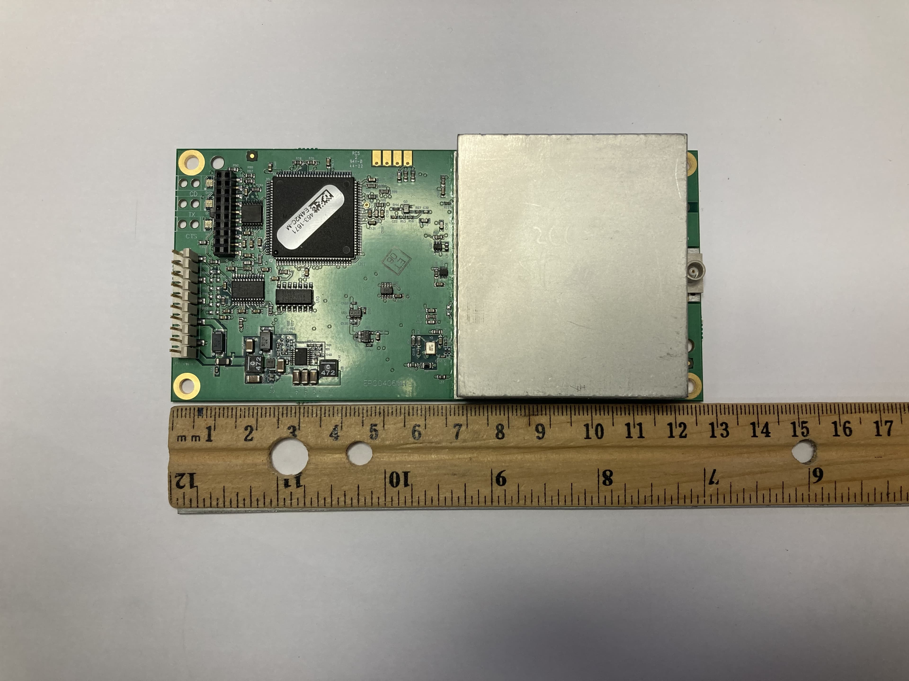
KNYLRS455C
Oct 01, 2023LR455C
Equipment Class
TNB - Licensed Non-Broadcast Station Transmitter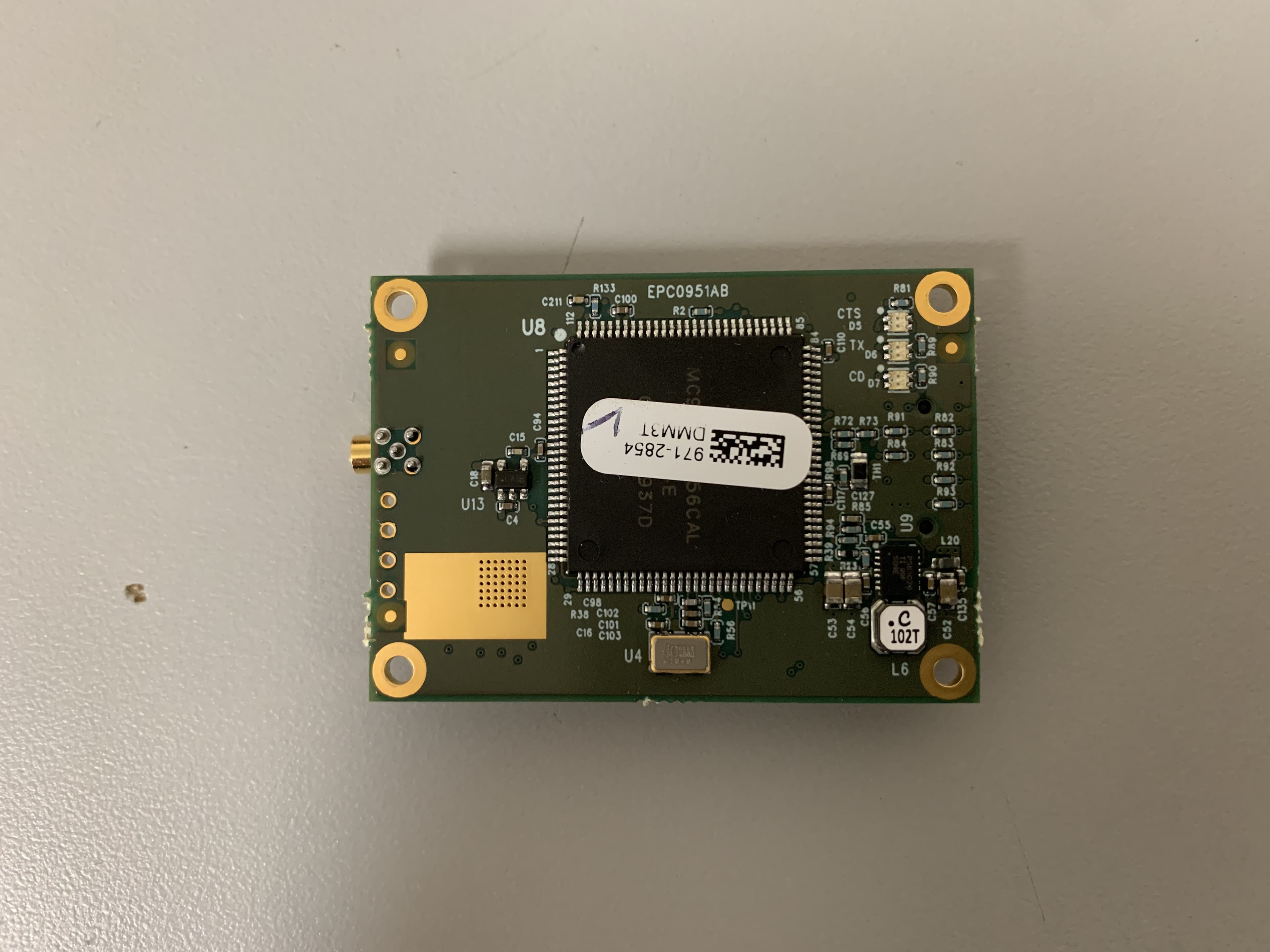
KNYMM3
Aug 25, 2020FHSS 902 - 928 MHz ISM band radio
Equipment Class
DSS - Part 15 Spread Spectrum Transmitter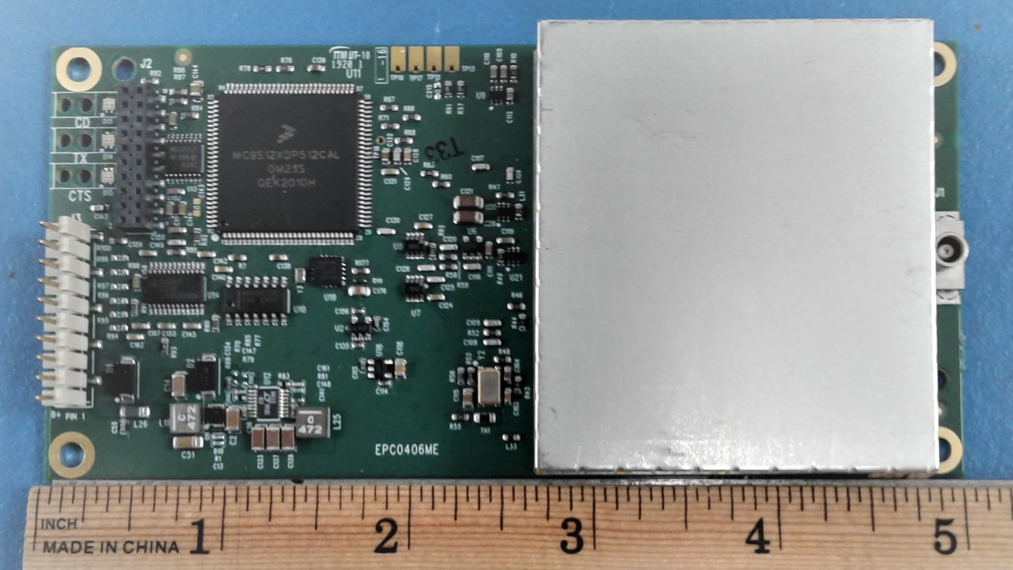
KNYLRS455A
Aug 04, 2020435-470 MHz Licensed Band Transceiver,
Equipment Class
TNB - Licensed Non-Broadcast Station Transmitter
KNYPRW5000AA
Oct 22, 2015Wireless 802.11ac/b/g/n access point
Equipment Class
DTS - Digital Transmission System
KNYAMM0921TT
Jan 14, 2014MM2
Equipment Class
DSS - Part 15 Spread Spectrum Transmitter