KNY821191151819435-470 MHz License Band Transceiver
FreeWave Technologies Inc.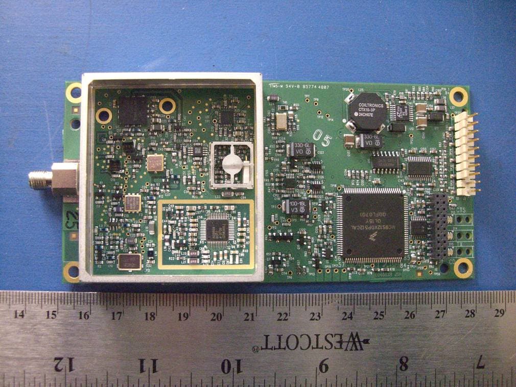
Click to zoom
Application Details
- Equipment Class
- TNB - Licensed Non-Broadcast Station Transmitter
- Date of Grant
- Mar 20, 2008
- Application Purpose
- Original Equipment
- Date of Application
- Mar 20, 2008
- Equipment Note
- 435-470 MHz License Band Transceiver
- Frequency Range
- 435.00000000 - 470.00000000
- Company
- FreeWave Technologies Inc.
- Country
- United States
Documents & Files
Document Text
Text extracted from the exhibit documents filed with the FCC. Open a document above to read the original.
Users Manual
Spread Spectrum Wireless Data Transceiver User Manual LUM0002AF Rev E Version 6.3 i Spread Spectrum Wireless Data Transceiver User Manual Version 6.3 FreeWave Technologies, Inc. 1880 South Flatiron Court Boulder, CO 80301 (303) 444-3862 (303) 786-9948 Fax www.FreeWave.com Spread Spectrum Wireless Data Transceiver User Manual LUM0002AF Rev E Version 6.3 ii SPREAD SPECTRUM WIRELESS DATA TRANSCEIVER USER MANUAL Copyright © 1995-2004 by FreeWave Technologies, Inc. All rights reserved. Published 2005. W ARRANTY FreeWave Technologies warrants the FreeWave Wireless Data Transceiver against defects in materials and manufacturing for a period of two years from the date of purchase. In the event of a Product failure due to materials or workmanship, FreeWave will, at its discretion, repair or replace the Product. In no event will FreeWave Technologies Inc., its suppliers, and its licensors be liable for any damages arising from the use of or inability to use this Product. This includes business interruption, loss of business information, or other loss which may arise from the use of this Product. Please be advised that OEM customer’s warranty periods may vary. Warranty Policy may not apply: 1. If Product repair, adjustments or parts replacements is required due to accident, neglect, unusual physical, electrical or electromagnetic stress. 2. If Product is used outside of FreeWave specifications. 3. If Product has been modified, repaired or altered by Customer unless FreeWave specifically authorized such alterations in each instance in writing. This includes the addition of conformal coating. The Warranty period begins from the date of shipment and is defined per the Standard Warranty Policy stated above. Special Rate Replacement Option A special rate replacement option is offered to non-warranty returns or upgrades. The option to purchase the replacement unit at this special rate is only valid for that RMA, (Return Material Authorization). The special replacement rate option expires if not exercised within 30 days of final disposition of RMA. R ESTRICTED RIGHTS Microsoft and Windows are registered trademarks of the Microsoft Corporation. pcANYWHERE is a registered trademark of Symantec Corporation. Other product names mentioned in this manual may be copyrights, trademarks, or registered trademarks of their respective companies and are hereby acknowledged. Information in this document is subject to change without notice. The information contained in this document is proprietary and confidential to FreeWave Technologies, Inc. This manual is for use by purchasers and other authorized users of the FreeWave™ Spread Spectrum Wireless Data Transceiver only. No part of this document may be reproduced or transmitted in any form or by any means, electronic or mechanical, or for any purpose without the express written permission of FreeWave Technologies, Inc. FreeWave’s Spread Spectrum Wireless Data Transceivers are made in the United States of America. Printed in the United States of America. Spread Spectrum Wireless Data Transceiver User Manual LUM0002AF Rev E Version 6.3 iii This product is licensed by The United States. Diversion contrary to U.S. law is prohibited. Shipment or re-export of this product outside of The United States may require authorization by the U.S. Bureau of Export Administration. Please contact FreeWave Technologies for assistance and further information. UL NOTIFICATION Model# FGRO9CSU is suitable for use in Class 1, Division 2, Groups A, B, C, and D or non-hazardous locations only. Input voltage for Model# FGRO9CSU is 6 to 30 volts DC. Model# DGRO9RFS is suitable for use in Class 1, Division 2, Groups A, B, C, and D or non-hazardous locations only. Input voltages for Model# DGRO9RFS are determined by the label on the bottom of the board. If the board has Label A shown below the input voltage is 6 to 14 volts DC. If the board has Label B shown below the input voltage is 6 to 14 volts DC at a maximum baud rate of 57.6 KBaud or 6 to 18 volts DC at a maximum baud rate of 19.2 KBaud, operation mode of MultiPoint Slave or MultiPoint Slave/Repeater only. Spread Spectrum Wireless Data Transceiver User Manual LUM0002AF Rev E Version 6.3 iv FCC NOTIFICATIONS This device complies with part 15 of the FCC rules. Operation is subject to the following two conditions: 1) This device may not cause harmful interference and 2) this device must accept any interference received, including interference that may cause undesired operation. This device must be operated as supplied by FreeWave Technologies, Inc. Any changes or modifications made to the device without the express written approval of FreeWave Technologies may void the user's authority to operate the device. CAUTION: The model number FGR09 has a maximum transmitted output power of 955mW. It is recommended that the transmit antenna be kept at least 23 cm away from nearby persons to satisfy FCC RF exposure requirements. The “I”-series transceiver have maximum transmitted output power of 500mW. It is recommended that the transmit antenna be kept at least 23 cm away from nearby persons to satisfy FCC RF exposure requirements. This equipment has been tested and found to comply with the limits for a Class B digital device, pursuant to part 15 of the FCC Rules. These limits are designed to provide reasonable protection against harmful interference in a residential installation. This equipment generates, uses, and can radiate radio frequency energy and, if not installed and used in accordance with the instructions, may cause harmful interference to radio communications. However, no guarantee shall be made that interference will not occur in a particular installation. If this equipment does cause harmful interference to radio or television reception, which can be determined by turning the equipment off and on, the user is encouraged to try to correct the interference by one or more of the following measures: • Reorient or relocate the receiving antenna. …
Text truncated - open the document above for the full version.
Cover Letter(s)
February 26, 2008 Federal Communications Commission Authorization and Evaluation Division Confidentiality Request regarding application for certification of FCC ID: KNY-821191151819 Pursuant to Sections 0.457 and 0.459 of the Commission’s Rules, we hereby request permanent confidential treatment of information accompanying this application as outlined below: - Detailed Circuit Schematics of EUT - Block Diagram - Parts List (BoM) - Tune up procedure - Theory of Operation The above materials contain trade secrets and proprietary information not customarily released to the public. The public disclosure of these materials may be harmful to the applicant and provide unjustified benefits to its competitors. The applicant understands that pursuant to Section 0.457 of the Rules, disclosure of this application and all accompanying documentation will not be made before the date of the Grant for this application. Sincerely, Richard Arment Engineer FreeWave Technologies 1880 S Flatiron Ct. Suite F. Boulder, CO 80301
Cover Letter(s)
1274 Anvilwood Ave., Sunnyvale, CA 94089 USA Tel.: 408.732.9162 Fax.: 408.732.9164 http://www.baclcorp.com 2009-07-30 Federal Communications Commission Authorization and Evaluation Division 7435 Oakland Mills Road Columbia, MD 21046 RE: Request to supersede test report for FCC ID: KNY821191151819 To Whom It May Concern: Regarding FCC ID: KNY821191151819; we are requesting to supersede the original test report due to an error was made in the measurement of Occupied Bandwidth. On page 15 and 16 of the original report that was uploaded on 03/21/2008, the Resolution Bandwidth (RBW) used was 3.0 KHz, but the correct Resolution Bandwidth (RBW) in our verification measurement recently should be 300 Hz. Therefore, the Occupied Bandwidth should be 9.65 KHz instead of incorrectly reported 12.5 KHz and the Emission Designator will also have to be changed on the FCC Grant to 9K65F1D instead of 12K5F1D. We would like to upload the corrected test report per the clients request so that we may correct this error. Thank you very much. Sincerely, Jessica Jiang, Technical Writer Document Control Department Bay Area Compliance Laboratories Corp. 1274 Anvilwood Avenue Sunnyvale, CA 94089, USA Tel: (408)-732-9162 (Ext.3040) Email: [email protected]
External Photos
FreeWave Technologies, Inc. KNY821191151819, IC: 2329B-LRS455 Report No.: R0802282 Page 34 of 36 FCC Part 90 and IC RSS-119 Test Report 13 EXHIBIT C - EUT PHOTOGRAPHS 13.1 EUT with Shield on – Front View 13.2 EUT with Shield off – Front View FreeWave Technologies, Inc. KNY821191151819, IC: 2329B-LRS455 Report No.: R0802282 Page 35 of 36 FCC Part 90 and IC RSS-119 Test Report 13.3 EUT – Back View 13.4 Power Supply – Front View
ID Label/Location Info
FreeWave Technologies, Inc. KNY821191151819, IC: 2329B-LRS455 Report No.: R0802282 Page 31 of 36 FCC Part 90 and IC RSS-119 Test Report 11 EXHIBIT A – FCC AND IC ID LABELING AND WARNING STATEMENT 11.1 FCC § 2.925 Identification of equipment (a) Each equipment covered in an application for equipment authorization shall bear a nameplate or label listing the following: (1) FCC Identifier consisting of the two elements in the exact order specified in §2.926. The FCC Identifier shall be preceded by the term FCC ID in capital letters on a single line, and shall be of a type size large enough to be legible without the aid of magnification. Example: FCC ID XXX123. XXX—Grantee Code 123—Equipment Product Code 11.2 IC RSS-Gen § 5.2 Equipment Labels: IC: XXXXXX-YYYYYYYY Where: • "XXXXXX-YYYYYYYY" is the certification number • "XXXXXX" is the Certificate Holder Number (CHN), made of at most 6 alphanumeric characters (A-Z, 0- 9), assigned by Industry Canada; and • "YYYYYYYY" is the Unique Product Number (UPN), made of at most 8 alphanumeric characters (A-Z, 0- 9) assigned by the applicant. • Note 1: The term "IC" before the equipment certification number only signifies that the Industry Canada technical specifications were met. • Note 2: Note 1 shall be conspicuously placed in the equipment user manual. • Note 3: Permitted alphanumeric characters used in the CHN and UPN are limited to capital letters (A-Z) and digits (0-9). Other characters, such as "#", "/" or "-", shall not be used. 11.3 Specifications: As per RSS GEN 5.2 Equipment Labeling: Equipment subject to certification under the applicable RSS, shall be permanently labeled on each item, or as an inseparable combination. The label must contain the following information for full compliance: (a) the certification number, prefixed by the term “IC:”; (b) the manufacturer's name, trade name or brand name; and (c) a model name or number. Equipment for which a certificate has been issued is not considered certified if it is not properly labeled. The information on the Canadian label can be combined with the manufacturer’s other labeling requirements. If the device size is too small to put a label, the label can be included in the user’s manual, upon agreement with Industry Canada. FreeWave Technologies, Inc. KNY821191151819, IC: 2329B-LRS455 Report No.: R0802282 Page 32 of 36 FCC Part 90 and IC RSS-119 Test Report 11.4 Suggested Label Location on EUT Top View of EUT / Suggested FCC ID Location
Internal Photos
FreeWave Technologies, Inc. KNY821191151819, IC: 2329B-LRS455 Report No.: R0802282 Page 34 of 36 FCC Part 90 and IC RSS-119 Test Report 13 EXHIBIT C - EUT PHOTOGRAPHS 13.1 EUT with Shield on – Front View 13.2 EUT with Shield off – Front View FreeWave Technologies, Inc. KNY821191151819, IC: 2329B-LRS455 Report No.: R0802282 Page 35 of 36 FCC Part 90 and IC RSS-119 Test Report 13.3 EUT – Back View 13.4 Power Supply – Front View
RF Exposure Info
FreeWave Technologies, Inc. KNY821191151819, IC: 2329B-LRS455 Report No.: R0802282 Page 10 of 36 FCC Part 90 and IC RSS-119 Test Report 4 §2.1091 & RSS- GEN 5.5 and RSS-102 – RF EXPOSURE 4.1 Applicability According to §1.1307(b)(1) and §1.1307(b)(2), systems operating under the provisions of this section shall be operated in a manner that ensures that the public is not exposed to radio frequency energy level in excess of the Commission’s guidelines. Limits for General Population/Uncontrolled Exposure Limits for General Population/Uncontrolled Exposure Frequency Range (MHz) Electric Field Strength (V/m) Magnetic Field Strength (A/m) Power Density (mW/cm 2 ) Averaging Time (minutes) 0.3-1.34 614 1.63 *(100) 30 1.34-30 824/f 2.19/f *(180/f 2 ) 30 30-300 27.5 0.073 0.2 30 300-1500 / / f/1500 30 1500-100,000 / / 1.0 30 f = frequency in MHz * = Plane-wave equivalent power density 4.2 MPE Prediction Prediction of MPE limit at a given distance Equation from page 18 of OET Bulletin 65, Edition 97-01 S = PG/4πR² Where: S = power density P = power input to antenna G = power gain of the antenna in the direction of interest relative to an isotropic radiator R = distance to the center of radiation of the antenna 4.3 Test Result The EUT is a PCB device which when situated 71 cm from the general public has a power density of 0.297 mW/cm 2 , which is below the uncontrolled limit of 0.303 mW/cm 2 . Maximum peak output power at antenna input terminal (dBm): 33.50 Maximum peak output power at antenna input terminal (mW): 2238.72 Prediction distance (cm): 71 Prediction frequency (MHz): 455 Maximum Antenna Gain, typical (dBi): 9.25 Maximum Antenna Gain (numeric): 8.41 Power density of prediction frequency at 71.0 cm (mW/cm 2 ): 0.297 MPE limit for uncontrolled exposure at prediction frequency (mW/cm 2 ): 0.303
Test Report
Note: This test report is for the customer shown above and their specific product only. It may not be duplicated or used in part without prior written consent from Bay Area Compliance Laboratories Corp. This report must not be used by the customer to claim product certification, approval, or endorsement by NVLAP, NIST, or any agency of the Federal Government . FCC PART 90 INDUSTRY CANADA RSS-119, ISSUE 9, JUNE 2007 MEASUREMENT AND TEST REPORT For FREEWAVE TECHNOLOGIES, INC. 1880 S. Flatiron Ct., Suite F Boulder, CO 80301 FCC ID: KNY821191151819 IC: 2329B-LRS455 Report Type: Original Report Product Type: Licensed Band Radio Transceiver Test Engineer: James Ma Report Number: R0802282 Testing Date(s): 2008-03-03, 2008-03-04, 2008-03-05 Report Date: 2008-03-06 Reviewed By: Boni Baniqued, Sr. RF Engineer Prepared By: (J8) Bay Area Compliance Laboratories Corp. 1274 Anvilwood Ave. Sunnyvale, CA 94089, USA Tel: (408) 732-9162 Fax: (408) 732 9164 FreeWave Technologies, Inc. KNY821191151819, IC: 2329B-LRS455 Report No.: R0802282 Page 2 of 36 FCC Part 90 and IC RSS-119 Test Report TABLE OF CONTENTS 1 GENERAL INFORMATION ..............................................................................................................................4 1.1 PRODUCT DESCRIPTION FOR EQUIPMENT UNDER TEST (EUT) ........................................................................4 1.2 MECHANICAL DESCRIPTION............................................................................................................................4 1.3 OBJECTIVE......................................................................................................................................................4 1.4 RELATED SUBMITTAL(S)/GRANT(S)................................................................................................................5 1.5 TEST METHODOLOGY.....................................................................................................................................5 1.6 MEASUREMENT UNCERTAINTY.......................................................................................................................5 1.7 TEST FACILITY................................................................................................................................................5 2 SYSTEM TEST CONFIGURATION .................................................................................................................7 2.1 JUSTIFICATION................................................................................................................................................7 2.2 EQUIPMENT MODIFICATIONS..........................................................................................................................7 2.3 POWER SUPPLY AND LINE FILTERS.................................................................................................................7 2.4 LOCAL SUPPORT EQUIPMENT LIST AND DETAILS...........................................................................................7 2.5 INTERFACE PORTS AND CABLING....................................................................................................................7 2.6 TEST SETUP BLOCK DIAGRAM........................................................................................................................8 3 SUMMARY OF TEST RESULTS ......................................................................................................................9 4 §2.1091 & RSS- GEN 5.5 and RSS-102 – RF EXPOSURE .............................................................................10 4.1 APPLICABILITY.............................................................................................................................................10 4.2 MPE PREDICTION.........................................................................................................................................10 4.3 TEST RESULT................................................................................................................................................10 5 §2.1046, §90.205 & RSS-119 §5.4.5 – RF OUTPUT POWER .........................................................................11 5.1 APPLICABLE STANDARD...............................................................................................................................11 5.2 7.2 TEST PROCEDURE....................................................................................................................................11 5.3 7.3 TEST EQUIPMENT LIST AND DETAILS......................................................................................................11 5.4 TEST RESULTS..............................................................................................................................................12 5.5 TEST RESULTS..............................................................................................................................................12 6 §2.1049, & §90.210 & RSS-119 §5.5 - OCCUPIED BANDWIDTH & EMMISON MASK..........................14 6.1 APPLICABLE STANDARD...............................................................................................................................14 6.2 TEST PROCEDURE.........................................................................................................................................14 6.3 ENVIRONMENTAL CONDITIONS.....................................................................................................................14 6.4 TEST EQUIPMENT LIST AND DETAILS............................................................................................................15 6.5 TEST RESULT................................................................................................................................................15 7 §2.1051 § 90.210 & RSS-119 §5.8 - SPURIOUS EMISSIONS AT ANTENNA TERMINALS ....................20 7.1 APPLICABLE…
Text truncated - open the document above for the full version.
Test Setup Photos
FreeWave Technologies, Inc. KNY821191151819, IC: 2329B-LRS455 Report No.: R0802282 Page 33 of 36 FCC Part 90 and IC RSS-119 Test Report 12 EXHIBIT B - TEST SETUP PHOTOGRAPHS 12.1 Radiated Emissions - Front View 12.2 Radiated Emissions - Rear View
Contact Information
Applicant
Richard Reisbick(VP Engineering)
Test Firm
Bay Area Compliance Laboratory Corp.John Chan
Technical Specifications
| # | Rule Parts | Frequency Range | Power Output | Emission | Tolerance |
|---|---|---|---|---|---|
| 1 | 90 | 435 MHz - 470 MHz | 2.24 W | 9K65F1D | 1.5000000000 ppm |
Other Applications from FreeWave Technologies Inc.
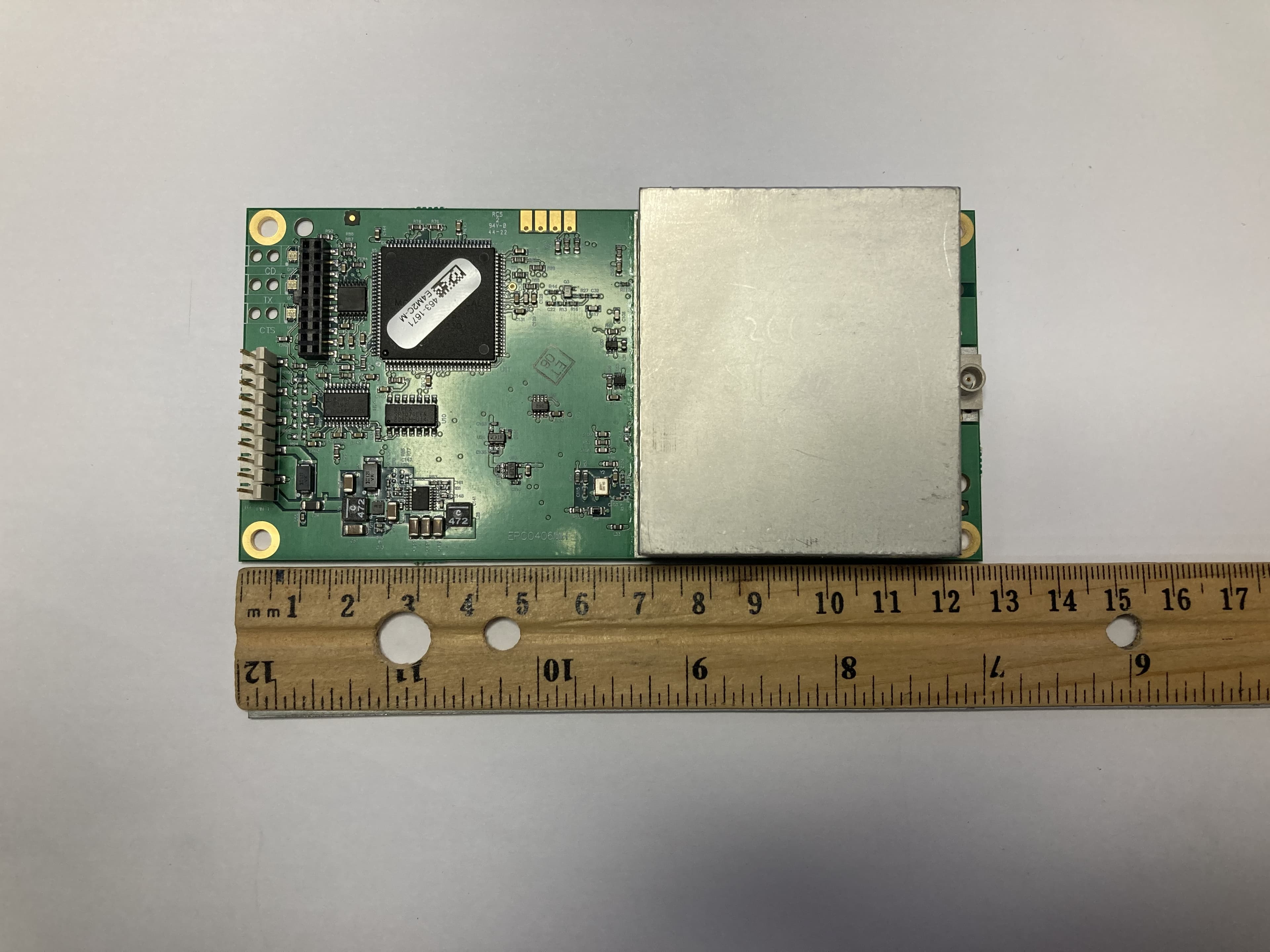
KNYLRS455C
Oct 01, 2023LR455C
Equipment Class
TNB - Licensed Non-Broadcast Station Transmitter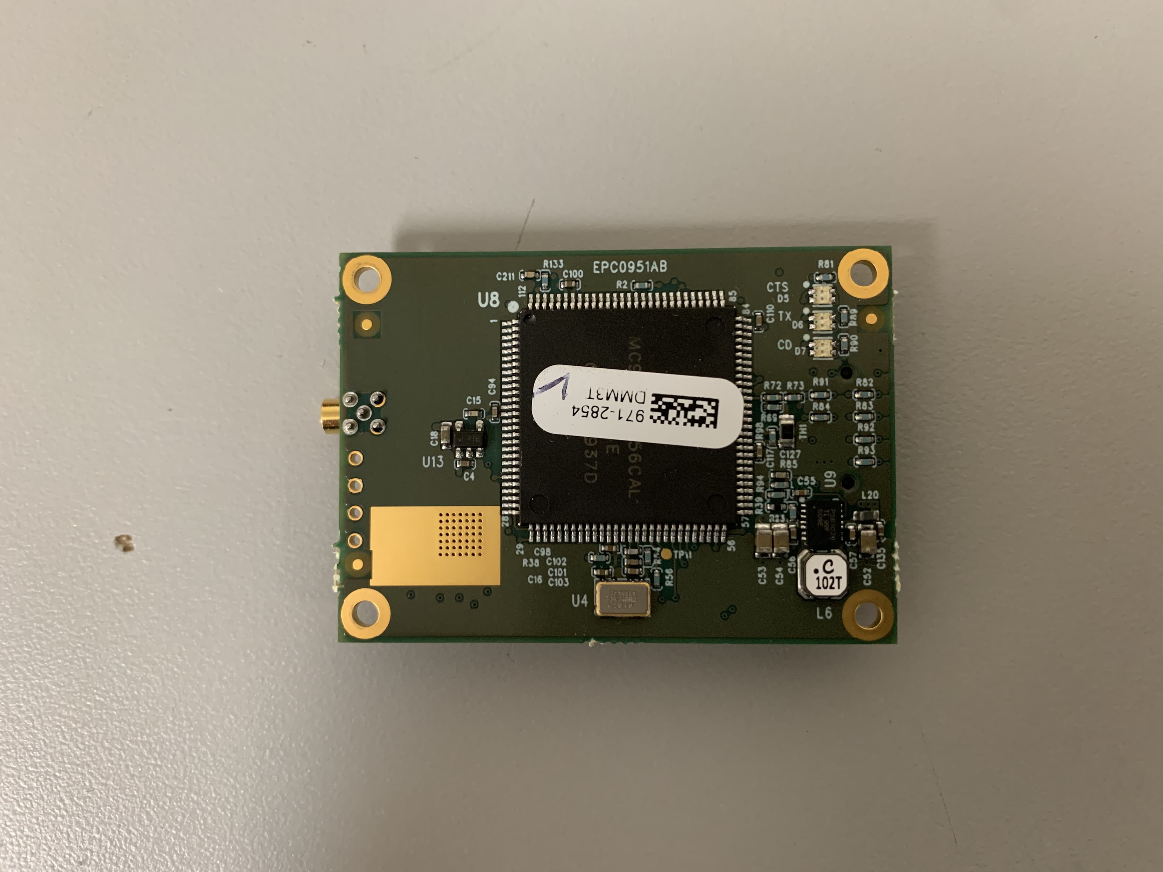
KNYMM3
Aug 25, 2020FHSS 902 - 928 MHz ISM band radio
Equipment Class
DSS - Part 15 Spread Spectrum Transmitter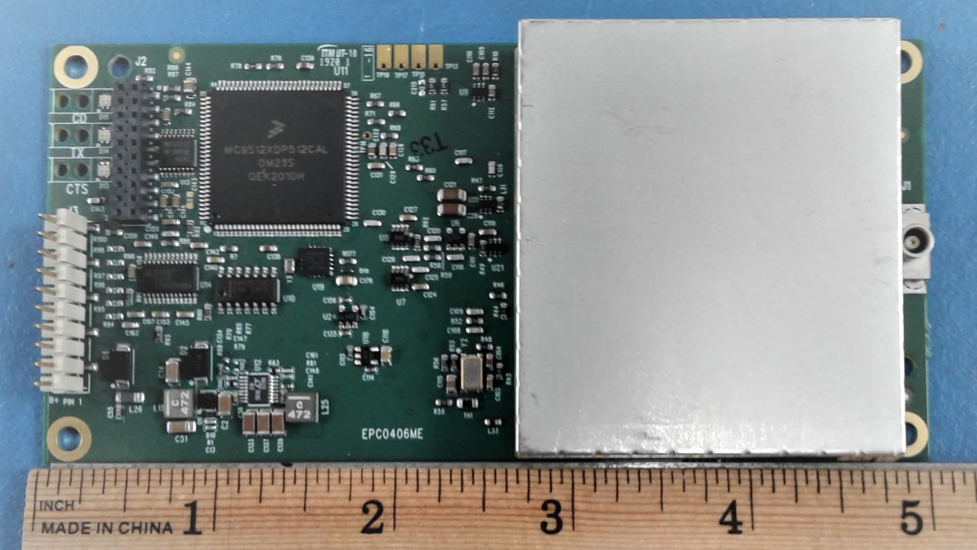
KNYLRS455A
Aug 04, 2020435-470 MHz Licensed Band Transceiver,
Equipment Class
TNB - Licensed Non-Broadcast Station Transmitter
KNYPRW5000AA
Oct 22, 2015Wireless 802.11ac/b/g/n access point
Equipment Class
DTS - Digital Transmission System
KNYAMM0921TT
Jan 14, 2014MM2
Equipment Class
DSS - Part 15 Spread Spectrum Transmitter