KNYARN2110ATFGRM
FreeWave Technologies Inc.
Click to zoom
Application Details
- Equipment Class
- DSS - Part 15 Spread Spectrum Transmitter
- Date of Grant
- Oct 24, 2013
- Application Purpose
- Original Equipment
- Date of Application
- Oct 24, 2013
- Equipment Note
- FGRM
- Frequency Range
- 902.25000000 - 927.82000000
- Company
- FreeWave Technologies Inc.
- Country
- United States
Documents & Files
Document Text
Text extracted from the exhibit documents filed with the FCC. Open a document above to read the original.
Users Manual
FreeWave Technologies October 22, 2013 900 MHz Spread Spectrum Installation Manual V5.3 LIG0003AC Rev D 1 of 11 FreeWave Technologies, Inc. 900 MHz Wireless Modem Installation Guide This installation guide covers all models of the FreeWave Technologies 900 MHz spread spectrum transceiver sold under FCC ID KNY-6231812519 and KNYARN2110AT. All transceiver models sold under FCC ID KNY-6231812519 and KNYARN2110AT must be installed professionally. These transceivers are only approved for use when installed in devices produced by FreeWave Technologies or third party OEMs approved by FreeWave Technologies. The antenna(s) to be used must be installed to provide a separation distance of at least 23 cm from all persons and must not be co-located or operating in conjunction with any other antenna or transmitter. This transceiver must be installed in a NEMA enclosure. FreeWave Technologies October 22, 2013 900 MHz Spread Spectrum Installation Manual V5.3 LIG0003AC Rev D 2 of 11 FCC Notification This device complies with part 15 of the FCC rules. Operation is subject to the following two conditions: 1) This device may not cause harmful interference and 2) this device must accept any interference received, including interference that may cause undesired operation. This device must be operated as supplied by FreeWave Technologies, Inc. Any changes or modifications made to the device without the express written approval of FreeWave Technologies may void the user's authority to operate the device. CAUTION: This device has a maximum transmitted output power of 955 mW. It is required that the transmit antenna be kept at least 23 cm away from nearby persons to satisfy FCC RF exposure requirements. Note: This equipment has been tested and found to comply with the limits for a Class B digital device, pursuant to part 15 of the FCC Rules. These limits are designed to provide reasonable protection against harmful interference in a residential installation. This equipment generates, uses and can radiate radio frequency energy and, if not installed and used in accordance with the instructions, may cause harmful interference to radio communications. However, there is no guarantee that interference will not occur in a particular installation. If this equipment does cause harmful interference to radio or television reception, which can be determined by turning the equipment off and on, the user is encouraged to try to correct the interference by one or more of the following measures: ♦ Reorient or relocate the receiving antenna. ♦ Increase the separation between the equipment and receiver. ♦ Connect the equipment into an outlet on a circuit different from that to which the receiver is connected. ♦ Consult the dealer or an experienced radio/TV technician for help. Note: Whenever any FreeWave Technologies module is placed inside an enclosure a label must be placed on the outside of that enclosure which includes the module's FCC ID. UL Notification Model DGRO9RFS: GENERAL: The device covered by this Report is a wireless data transceiver. It must be installed in a suitable enclosure. FreeWave Technologies October 22, 2013 900 MHz Spread Spectrum Installation Manual V5.3 LIG0003AC Rev D 3 of 11 RATINGS: The device is supplied by a NEC Class 2 Power Supply supplying: 6 V dc to 14 V dc at 600 mA @ 57.6 KBAUD max. 6 V dc to 18 V dc at 600 mA @ 19.2 KBAUD max. Conditions of Acceptability – When installed in the end use equipment, the following considerations are to be examined: 1. The transceivers shall be mounted within an enclosure which is suitable for the intended application. The enclosure shall also have provisions for Division 2 wiring methods as specified in the National Electrical Code or Canadian Electrical Code, as applicable. 2. The transceivers must be used within their Recognized “Ratings” at an acceptable transmission rate. “Increasing the baud rate may impair the safety characteristics for Class I, Division 2 Hazardous Locations.” 3. Installations and use should be in accordance with the National Electrical Code or Canadian Electrical Code, as applicable. 4. The connectors shall not be connected or disconnected while circuit is alive unless area is known to be nonhazardous. 5. The end product shall be marked with a warning for the end user indicating that changes to the baud rate may impair the safety characteristics for Class I, Division 2 Hazardous Locations. Input voltages for Model# DGRO9RFS are determined by the label on the bottom of the board. If the board has Label A shown below the input voltage is 6 to 14 volts DC. If the board has Label B shown below the input voltage is 6 to 14 volts DC at a maximum baud rate of 57.6 KBaud or 6 to 18 volts DC at a maximum baud rate of 19.2 KBaud, operation mode of multipoint slave or multipoint slave/repeater only. Class 1 Div 2 Label A Class 1 Div 2 Label B FreeWave Technologies October 22, 2013 900 MHz Spread Spectrum Installation Manual V5.3 LIG0003AC Rev D 4 of 11 Models FGR2-IOS-T-U*, FGR2-IOS-TE-U*, FGR2-IOS-C-U, FGR2-IOS-CE-U, FGR2-TE-U*, FGR2-CE-U, FGR2-RE-U*, FGR2-C-U, FGR2-T-U*, FGR2-R-U* FGRM-C2, and FGRM-C3. * Model not currently in production GENERAL: The devices covered by this Report are wireless data transceivers. These devices are intended to be installed in a suitable enclosure. RATINGS: The devices are powered by a NEC Class 2 Power Supply: Operating voltage range 6 V dc to 30 V dc at 500 mA(Avg) Maximum operating ambient temperature is 40° C. Conditions of Acceptability – When installed in the end use equipment, the following considerations are to be examined: 1. The transceivers shall be mounted within an enclosure which is suitable for the intended application. The enclosure shall also have provisions for Division 2 wiring methods as specified in the National Electrical Code or Canadian Electrical Code, as applicable. 2. The transceivers must be used within their Recognized “Ratings” and conditions of acceptability as referenced in Users Manu…
Text truncated - open the document above for the full version.
Cover Letter(s)
WTD 13.4.9 FCC Compliance Opinion FREW0013 Information about the Applicant Grantee (Company Name) FreeWave Technologies, Inc. FCC Contact Person Dean Busch Address 5395 Pearl Parkway, Suite 100 City, State, Zip Boulder, CO 80301 Job Number FREW0013 Model FGRM FCC ID KNYARN2110AT Agent NA Approval Type Original Equipment Class DSS Part 15, Spread Spectrum Transmitter Rule Part 15.247 Overview This application is for the certification of a FHSS Industrial radio that operates at 902 - 928 MHz. The radio must be professionally installed and is not available to the public through normal marketing channels. The MPE report shows that the necessary separation distance for safe operation is 23 cm. Confidentiality requested for allowed files. Request is properly addressed and referenced. No short term confidentiality requested. Recommendation All items have been resolved and completed to my satisfaction; therefore I recommend this application for approval. Signature Dave Tolman, TCB Committee 10/24/2013
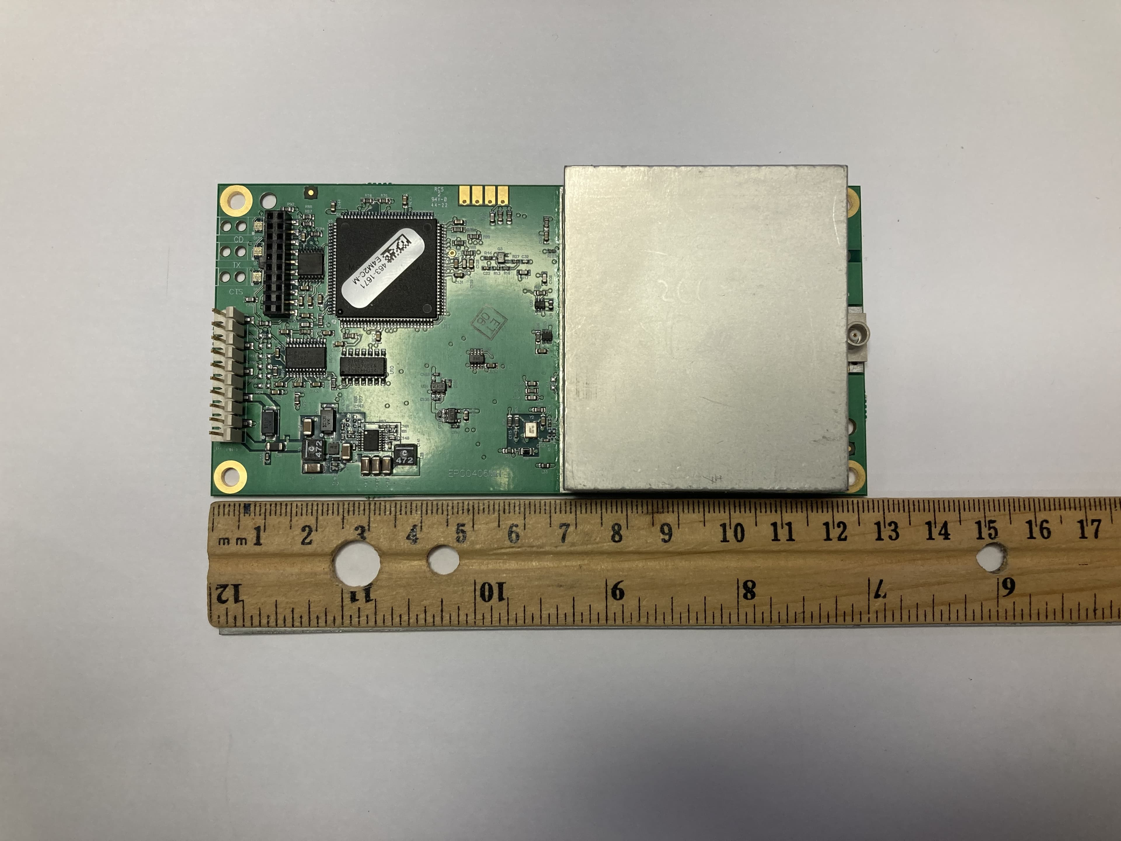
External Photos
Radio Top 2 Radio Bottom
Internal Photos
2 Radio Bottom 3 Radio without Cover
Operational Description
OMNI-DIRECTIONAL ANTENNAS FG9026 (902 - 928 MHz) 0 8 0 ° 7 0 ° 6 0 ° 5 0 ° 4 0 ° 3 0 ° 2 0 ° 1 0 ° 3 5 0 ° 3 4 0 ° 3 3 0 ° 3 2 0 ° 3 1 0 ° 3 0 0 ° 2 9 0 ° 2 8 0 ° 270° 2 6 0 ° 2 5 0 ° 2 4 0 ° 2 3 0 ° 2 2 0 ° 2 1 0 ° 2 0 0 ° 1 9 0 ° 180° 1 7 0 ° 1 6 0 ° 1 5 0 ° 1 4 0 ° 1 3 0 ° 1 2 0 ° 1 1 0 ° 1 0 0 ° 90° -2 -6 -8 -10 -20 -30 -40 -50 -4 Normalized to 6dBd FEATURES ● High Performance ● Easy installation /w optional FM2 ● Special UV treated radome, resists sun damage ● N Female industry standard connector ● 100% tested on a network analyzer Elevation Pattern (Y, Z or H-plane) MECHANICAL SPECIFICATIONS Height: 61” Diameter: 1.310” Weight: 0.5 lb Rated Wind Velocity: 125mph (210kph) Rated Wind Velocity (with 0.5” radial ice) 85mph (137kph) Lateral Thrust @ 125mph WIND VELOCITY 57 lbs. (26kg) Wind Resistance in Sq. Feet: 0.5549 Mounting Information: FM2 Mounting Kit (Sold separately) ELECTRICAL SPECIFICATIONS Frequency Range: 902 - 928 MHz VSWR: < 1.5:1 Max Nominal Gain: 6dBd Maximum Power: 100 W Nominal Impedance: 50Ω Polarization: Vertical Pattern: Omni-Directional Half-Power Beamwidth: 30° x 360° (Elevation° x Azimuth°) Coaxial Cable Length & Type: None Termination: N-Female connector Lightning Protection: Lightning Arrestor LABH350NN (Sold Separately) 2000-205 Bloomingdale Road • Glendale Heights, Illinois 60139 U.S.A. • Web Site: Http://www.antenex.com 630-351-9007 • Fax: 630-351-9009 • Order line: 800-323-3757 Page 1 of 1 Confidential Information N:\Antenex\Engineering Dept\Web Data\Product Information by Family\Fiberglass Omnidirectional\Spec\FG9026_Spec\FG9026_Spec.doc
RF Exposure Info
FreeWave Technologies, Inc. FGRM Report No. FREW0013.2 FCC 2.1091:2013 Maximum Permissible Exposure Level Report Prepared By Northwest EMC Inc. NORTHWEST EMC – (888) 364-2378 – www.nwemc.com California – Minnesota – Oregon – New York – Washington 22975 NW Evergreen Parkway Suite 400 Hillsboro, Oregon 97124 Certificate of Evaluation Date of Evaluation: October 22, 2013 FreeWave Technologies, Inc. Model: FGRM Emissions Description of Evaluation Specification Evaluation Method Pass/Fail Maximum Permissible Exposure FCC 2.1091:2013 OET Bulletin 65, Supplement C Ed 01-01 Pass Approved By: Don Facteau, IS Manager NVLAP Lab Code: 200630-0 This report must not be used to claim product certification, approval, or endorsement by NVLAP, NIST, or any agency of the federal government of the United States of America. Product compliance is the responsibility of the client, therefore the tests and equipment modes of operation represented in this report were agreed upon by the client, prior to testing. This Report may only be duplicated in its entirety. The results of this test pertain only to the sample(s) tested. The specific description is noted in each of the individual sections of the test report supporting this certificate of test. Report No. FREW0013.22/9 REV 2012.08.02 REVISION HISTORY Revision Number Description Date Page Number 00 None Barometric Pressure The recorded barometric pressure has been normalized to sea level. Report No. FREW0013.23/9 REV 2012.05.24 ACCREDITATIONS AND AUTHORIZATIONS United States FCC - Designated by the FCC as a Telecommunications Certification Body (TCB). Certification chambers, Open Area Test Sites, and conducted measurement facilities are listed with the FCC. A2LA - Accredited by A2LA to ISO / IEC Guide 65 as a product certifier. This allows Northwest EMC to certify transmitters to FCC and IC specifications. NVLAP - Each laboratory is accredited by NVLAP to ISO 17025 Canada IC - Recognized by Industry Canada as a Certification Body (CB). Certification chambers and Open Area Test Sites are filed with IC. European Union European Commission – Validated by the European Commission as a Conformity Assessment Body (CAB) under the EMC directive and as a Notified Body under the R&TTE Directive. Australia/New Zealand ACMA - Recognized by ACMA as a CAB for the acceptance of test data. Korea KCC / RRA - Recognized by KCC’s RRA as a CAB for the acceptance of test data. Japan VCCI - Associate Member of the VCCI. Conducted and radiated measurement facilities are registered. Taiwan BSMI – Recognized by BSMI as a CAB for the acceptance of test data. NCC - Recognized by NCC as a CAB for the acceptance of test data. Singapore IDA – Recognized by IDA as a CAB for the acceptance of test data. Hong Kong OFTA – Recognized by OFTA as a CAB for the acceptance of test data. Vietnam MIC – Recognized by MIC as a CAB for the acceptance of test data. Russia GOST – Accredited by Certinform VNIINMASH, CERTINFO, SAMTES, and Federal CHEC to perform EMC and Hygienic testing for Information Technology products to GOST standards. SCOPE For details on the Scopes of our Accreditations, please visit: http://www.nwemc.com/accreditations/ Report No. FREW0013.24/9 REV 2013.02.26 LOCATIONS Oregon Labs EV01-12 22975 NW Evergreen Pkwy Hillsboro, OR 97124 (503) 844-4066 California Labs OC01-13 41 Tesla Irvine, CA 92618 (949) 861-8918 New York Labs NY01-04 4939 Jordan Rd. Elbridge, NY 13060 (315) 685-0796 Minnesota Labs MN01-08 9349 W Broadway Ave. Brooklyn Park, MN 55445 (763) 425-2281 Washington Labs NC01-05,SU02,SU07 19201 120 th Ave. NE Bothell, WA 98011 (425) 984-6600 VCCI A-0108 A-0029 A-0109 A-0110 Industry Canada 2834D-1, 2834D-2 2834B-1, 2834B-2, 2834B-3 2834E-1 2834C-1 NVLAP NVLAP Lab Code: 200630-0 NVLAP Lab Code: 200676-0 NVLAP Lab Code: 200761-0 NVLAP Lab Code: 200881-0 NVLAP Lab Code: 200629-0 Report No. FREW0013.25/9 Product Description Revision 09/01/11 Client and Equipment Under Test (EUT) Information Company Name: FreeWave Technologies, Inc. Address: 5395 Pearl Parkway, Suite 100 City, State, Zip: Boulder, CO 80301 Test Requested By: Dean Busch Model: FGRM Date of Evaluation: October 22, 2013 Information Provided by the Party Requesting the Test Functional Description of the EUT (Equipment Under Test): 900 MHz FHSS radio module with 1 antenna(s). Max power is 1 W Objective: To demonstrate compliance with FCC requirements for RF exposure for 2.1091 mobile devices Report No. FREW0013.26/9 WD.12.29.11 Maximum Permissible Exposure (MPE) OVERVIEW Human exposure to RF emissions from mobile devices (47 CFR §2.1091) may be evaluated based on the MPE limits adopted by the FCC for electric and magnetic field strength and/or power density, as appropriate, since exposures are assumed to occur at distances of 20 cm or more from persons. ANSI C95.1-1992 specifies a minimum separation distance of 20 cm for performing reliable field measurements to determine adherence to MPE limits. If the minimum separation distance between a transmitter and nearby persons is more than 20 cm under normal operating conditions, compliance with MPE limits may be determined at such distance from the transmitter. When applicable, operation instructions and prominent warning labels may be used to alert the exposed persons to maintain a specified distance from the transmitter or to limit their exposure durations and usage conditions to ensure compliance. If the use of warning labels on a transmitter is not effective or desirable, the alternative of performing SAR evaluation with the device at its closest range to persons under normal operating conditions may be used. The field strength and power density limits adopted by the FCC are based on whole-body averaged exposure and the assumption of RF field levels relate most accurately to estimating whole-body averaged SAR. This means some local values of exposures exceeding the stated field strength and power density limits may not necessarily imply non-compliance if the spatial average…
Text truncated - open the document above for the full version.
Test Report
FreeWave Technologies, Inc. FGRM FCC 15.247:2013 FCC 15.207:2013 Report #: FREW0013 Report Prepared By Northwest EMC Inc. NORTHWEST EMC – (888) 364-2378 – www.nwemc.com California – Minnesota – Oregon – New York – Washington WTD 12.5.23 CERTIFICATE OF TEST Last Date of Test: October 15, 2013 FreeWave Technologies, Inc. Model: FGRM Emissions Test Description Specification Test Method Pass/Fail Duty Cycle FCC 15.247:2013 ANSI C63.10:2009 Pass Output Power FCC 15.247:2013 ANSI C63.10:2009 Pass Occupied Bandwidth FCC 15.247:2013 ANSI C63.10:2009 Pass Spurious Conducted Emissions FCC 15.247:2013 ANSI C63.10:2009 Pass Band Edge Compliance FCC 15.247:2013 ANSI C63.10:2009 Pass Channel Separation FCC 15.247:2013 ANSI C63.10:2009 Pass Number of Hopping Channels FCC 15.247:2013 ANSI C63.10:2009 Pass Dwell Time FCC 15.247:2013 ANSI C63.10:2009 Pass Band Edge Compliance-Hopping Mode FCC 15.247:2013 ANSI C63.10:2009 Pass Spurious Radiated Emissions FCC 15.247:2013 ANSI C63.10:2009 Pass Powerline Conducted Emissions FCC 15.207:2013 ANSI C63.10:2009 Pass Deviations From Test Standards None Approved By: Tim O'Shea, Operations Manager NVLAP Lab Code: 200629-0 NVLAP Lab Code: 200630-0 This report must not be used to claim product certification, approval, or endorsement by NVLAP, NIST, or any agency of the federal government of the United States of America. Product compliance is the responsibility of the client, therefore the tests and equipment modes of operation represented in this report were agreed upon by the client, prior to testing. This Report may only be duplicated in its entirety. The results of this test pertain only to the sample(s) tested. The specific description is noted in each of the individual sections of the test report supporting this certificate of test. REV 2012.08.02 REVISION HISTORY Revision Number Description Date Page Number 00 None Barometric Pressure The recorded barometric pressure has been normalized to sea level. REV 2012.05.24 ACCREDITATIONS AND AUTHORIZATIONS United States FCC - Designated by the FCC as a Telecommunications Certification Body (TCB). Certification chambers, Open Area Test Sites, and conducted measurement facilities are listed with the FCC. A2LA - Accredited by A2LA to ISO / IEC Guide 65 as a product certifier. This allows Northwest EMC to certify transmitters to FCC and IC specifications. NVLAP - Each laboratory is accredited by NVLAP to ISO 17025 Canada IC - Recognized by Industry Canada as a Certification Body (CB). Certification chambers and Open Area Test Sites are filed with IC. European Union European Commission – Validated by the European Commission as a Conformity Assessment Body (CAB) under the EMC directive and as a Notified Body under the R&TTE Directive. Australia/New Zealand ACMA - Recognized by ACMA as a CAB for the acceptance of test data. Korea KCC / RRA - Recognized by KCC’s RRA as a CAB for the acceptance of test data. Japan VCCI - Associate Member of the VCCI. Conducted and radiated measurement facilities are registered. Taiwan BSMI – Recognized by BSMI as a CAB for the acceptance of test data. NCC - Recognized by NCC as a CAB for the acceptance of test data. Singapore IDA – Recognized by IDA as a CAB for the acceptance of test data. Hong Kong OFTA – Recognized by OFTA as a CAB for the acceptance of test data. Vietnam MIC – Recognized by MIC as a CAB for the acceptance of test data. Russia GOST – Accredited by Certinform VNIINMASH, CERTINFO, SAMTES, and Federal CHEC to perform EMC and Hygienic testing for Information Technology products to GOST standards. SCOPE For details on the Scopes of our Accreditations, please visit: http://www.nwemc.com/accreditations/ REV 2013.03.8 MEASUREMENT UNCERTAINTY Measurement Uncertainty When a measurement is made, the result will be different from the true or theoretically correct value. The difference is the result of tolerances in the measurement system that cannot be completely eliminated. To the extent that technology allows us, it has been our aim to minimize this error. Measurement uncertainty is a statistical expression of measurement error qualified by a probability distribution. A measurement uncertainty estimation has been performed for each test per our internal quality document WP 342. The estimation is used to compare the measured result with its "true" or theoretically correct value. The expanded measurement uncertainty (K=2) for each test is listed below. Our measurement data meets or exceeds the measurement uncertainty requirements of the applicable specification; therefore, the test data can be compared directly to the specification limit to determine compliance. The calculations for estimating measurement uncertainty are based upon ETSI TR 100 028 (or CISPR 16-4-1 as applicable), and are available upon request. The following table represents the Measurement Uncertainty (MU) budgets for each of the tests that may be contained in this report. Test + MU - MU Frequency Accuracy (Hz) 0.12 -0.01 Amplitude Accuracy (dB) 0.49 -0.49 Conducted Power (dB) 0.41 -0.41 Radiated Power via Substitution (dB) 0.69 -0.68 Temperature (degrees C) 0.81 -0.81 Humidity (% RH) 2.89 -2.89 Field Strength (dB) 3.80 -3.80 AC Powerline Conducted Emissions (dB) 2.94 -2.94 REV 2013.06.28 FACILITIES Oregon Labs EV01-12 22975 NW Evergreen Pkwy Hillsboro, OR 97124 (503) 844-4066 California Labs OC01-13 41 Tesla Irvine, CA 92618 (949) 861-8918 New York Labs NY01-04 4939 Jordan Rd. Elbridge, NY 13060 (315) 685-0796 Minnesota Labs MN01-08 9349 W Broadway Ave. Brooklyn Park, MN 55445 (763) 425-2281 Washington Labs NC01-05,SU02,SU07 19201 120 th Ave. NE Bothell, WA 98011 (425) 984-6600 VCCI A-0108 A-0029 A-0109 A-0110 Industry Canada 2834D-1, 2834D-2 2834B-1, 2834B-2, 2834B-3 2834E-1 2834C-1 NVLAP NVLAP Lab Code: 200630-0 NVLAP Lab Code: 200676-0 NVLAP Lab Code: 200761-0 NVLAP Lab Code: 200881-0 NVLAP Lab Code: 200629-0 WTD 12.5.23 PRODUCT DESCRIPTION Client and Equipment Under Test (EUT) Information Company Name: FreeWave Tech…
Text truncated - open the document above for the full version.
Test Setup Photos
Duty Cycle XMit 2013.08.15 NORTHWEST Duty Cycle PsaTx 2013.07.11 EMC EV06 001.JPG EV06 002.JPG Duty Cycle Report-FREW00131/21 Duty Cycle XMit 2013.08.15 NORTHWEST Duty Cycle PsaTx 2013.07.11 EMC EV06 003.JPG Duty Cycle Report-FREW00132/21 Output Power XMit 2013.08.15 NORTHWEST Output Power PsaTx 2013.07.11 EMC EV06 001.JPG EV06 002.JPG Output Power Report-FREW00133/21 Output Power XMit 2013.08.15 NORTHWEST Output Power PsaTx 2013.07.11 EMC EV06 003.JPG Output Power Report-FREW00134/21 Occupied Bandwidth XMit 2013.08.15 NORTHWEST Occupied Bandwidth PsaTx 2013.07.11 EMC EV06 001.JPG EV06 002.JPG Occupied Bandwidth Report-FREW00135/21 Occupied Bandwidth XMit 2013.08.15 NORTHWEST Occupied Bandwidth PsaTx 2013.07.11 EMC EV06 003.JPG Occupied Bandwidth Report-FREW00136/21 Spurious Conducted Emissions XMit 2013.08.15 NORTHWEST Spurious Conducted PsaTx 2013.07.11 EMC EV06 001.JPG EV06 002.JPG Spurious Conducted Emissions Report-FREW00137/21 Spurious Conducted Emissions XMit 2013.08.15 NORTHWEST Spurious Conducted PsaTx 2013.07.11 EMC EV06 003.JPG Spurious Conducted Emissions Report-FREW00138/21 Band Edge Compliance XMit 2013.08.15 NORTHWEST Band Edge Complian PsaTx 2013.07.11 EMC EV06 001.JPG EV06 002.JPG Band Edge Compliance Report-FREW00139/21 Band Edge Compliance XMit 2013.08.15 NORTHWEST Band Edge Complian PsaTx 2013.07.11 EMC EV06 003.JPG Band Edge Compliance Report-FREW001310/21 Channel Separation XMit 2013.08.15 NORTHWEST Channel Separation PsaTx 2013.07.11 EMC EV06 001.JPG EV06 002.JPG Channel Separation Report-FREW001311/21 Channel Separation XMit 2013.08.15 NORTHWEST Channel Separation PsaTx 2013.07.11 EMC EV06 003.JPG Channel Separation Report-FREW001312/21 Number of Hopping Channels XMit 2013.08.15 NORTHWEST Number of Hopping C EMC EV06 001.JPG EV06 002.JPG Number of Hopping Channels Report-FREW001313/21 Number of Hopping Channels XMit 2013.08.15 NORTHWEST Number of Hopping C EMC EV06 003.JPG Number of Hopping Channels Report-FREW001314/21 Dwell Time XMit 2013.08.15 NORTHWEST Dwell Time PsaTx 2013.07.11 EMC EV06 001.JPG EV06 002.JPG Dwell Time Report-FREW001315/21 Dwell Time XMit 2013.08.15 NORTHWEST Dwell Time PsaTx 2013.07.11 EMC EV06 003.JPG Dwell Time Report-FREW001316/21 Band Edge Compliance- Hopping Mode XMit 2013.08.15 NORTHWEST Band Edge Complian PsaTx 2013.07.11 EMC EV06 001.JPG EV06 002.JPG Band Edge Compliance- Hopping Mode Report-FREW001317/21 Band Edge Compliance- Hopping Mode XMit 2013.08.15 NORTHWEST Band Edge Complian PsaTx 2013.07.11 EMC EV06 003.JPG Band Edge Compliance- Hopping Mode Report-FREW001318/21 photo SRE - Flat.JPG SRE - Horz.JPG SPURIOUS RADIATED EMISSIONS PSA-ESCI 2012.12.14 Report-FREW001319/21 photo SRE - Vert.JPG SRE (2).JPG SPURIOUS RADIATED EMISSIONS PSA-ESCI 2012.12.14 Report-FREW001320/21 photo SRE (3).JPG SPURIOUS RADIATED EMISSIONS PSA-ESCI 2012.12.14 Report-FREW001321/21
Contact Information
Applicant
Richard Reisbick(VP Engineering)
Test Firm
Northwest EMC, Inc.Greg Kiemel
Technical Specifications
| # | Rule Parts | Frequency Range | Power Output |
|---|---|---|---|
| 1 | 15C | 902.25 MHz - 927.82 MHz | 965.00 mW |
Other Applications from FreeWave Technologies Inc.
KNYLRS455C
Oct 01, 2023LR455C
Equipment Class
TNB - Licensed Non-Broadcast Station Transmitter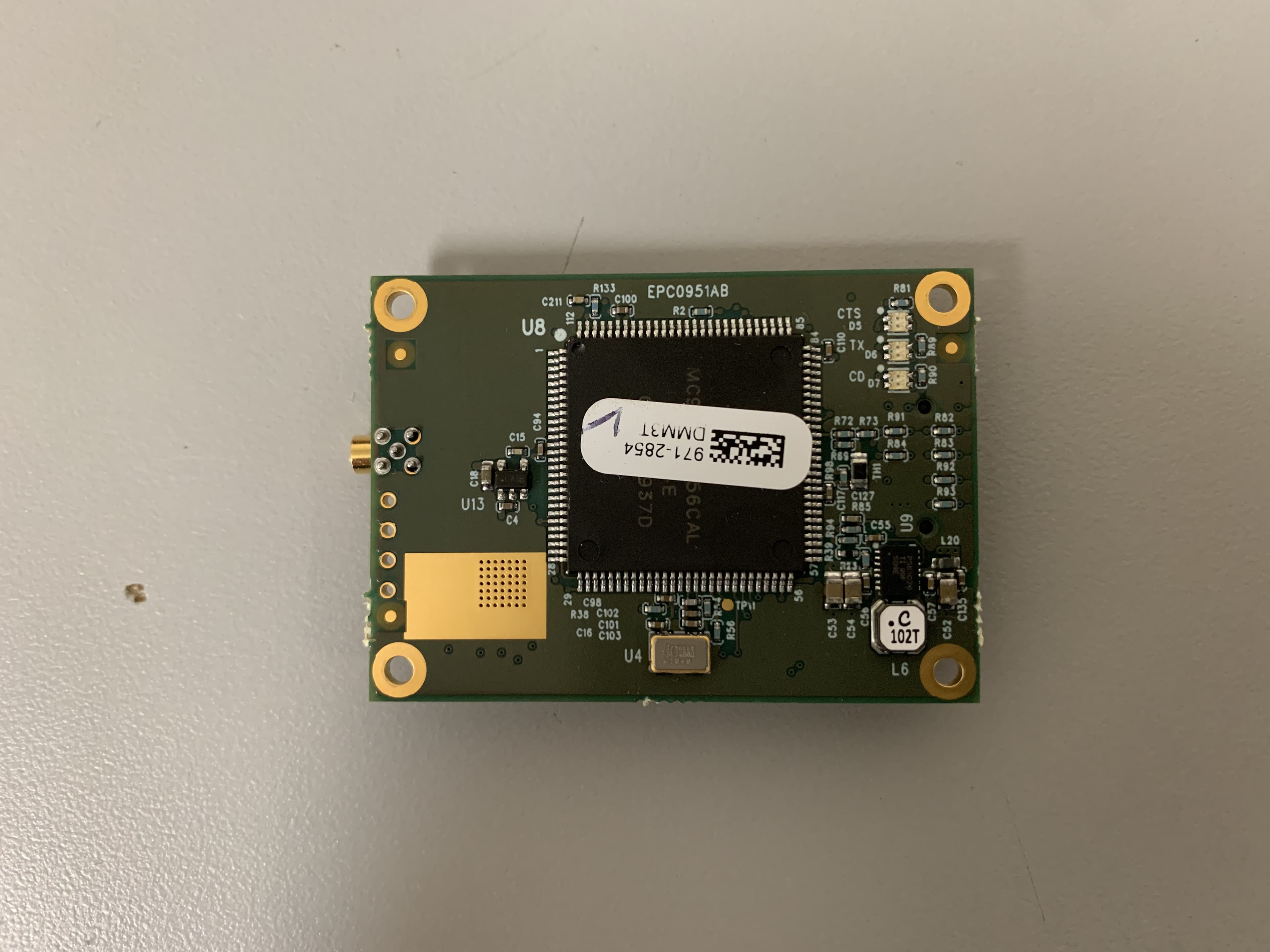
KNYMM3
Aug 25, 2020FHSS 902 - 928 MHz ISM band radio
Equipment Class
DSS - Part 15 Spread Spectrum Transmitter
KNYLRS455A
Aug 04, 2020435-470 MHz Licensed Band Transceiver,
Equipment Class
TNB - Licensed Non-Broadcast Station Transmitter
KNYPRW5000AA
Oct 22, 2015Wireless 802.11ac/b/g/n access point
Equipment Class
DTS - Digital Transmission System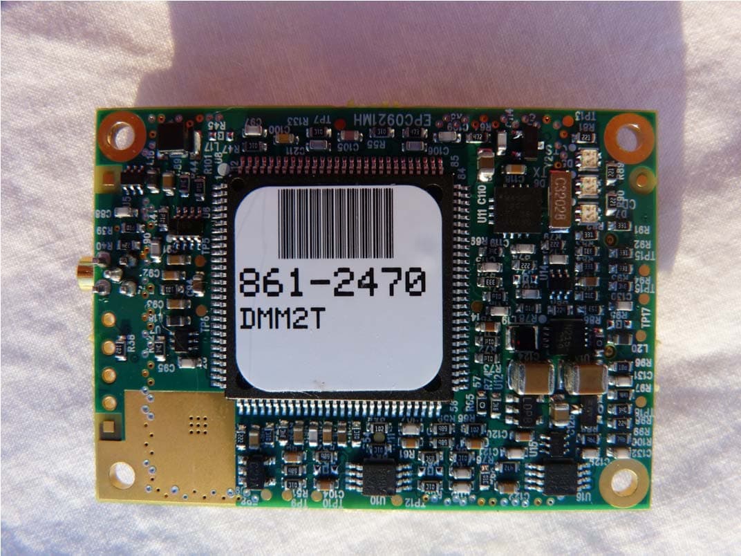
KNYAMM0921TT
Jan 14, 2014MM2
Equipment Class
DSS - Part 15 Spread Spectrum Transmitter