KOC-901782Bluetooth RS232 DTE adapter
Smart Modular Technologies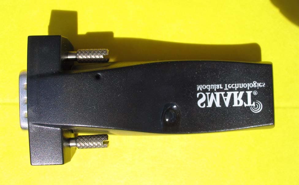
Click to zoom
Application Details
- Equipment Class
- DSS - Part 15 Spread Spectrum Transmitter
- Date of Grant
- Jul 04, 2004
- Application Purpose
- Original Equipment
- Date of Application
- Jul 04, 2004
- Equipment Note
- Bluetooth RS232 DTE adapter
- Frequency Range
- 2402.00000000 - 2480.00000000
- Company
- Smart Modular Technologies
- Country
- United States
Documents & Files
Document Text
Text extracted from the exhibit documents filed with the FCC. Open a document above to read the original.
Users Manual
User’s Guide RS232 Bluetooth Adapter Version: 2.8 SMART Modular Technologies, Inc., 4211 Starboard Drive, Fremont, CA 94538 Web: www.smartm.com Technical support: www.smartm.com/btsupport STBTIOBxXXPARSM User Guide 2.8 © Copyright SMART Modular Technologies 2004 Page 1 of 30 Table of Contents 1. Introduction ....................................................................................................................................4 2. Products and Firmware .....................................................................................................................4 3. Physical Product Features .................................................................................................................4 3.1. ADAPTER ...............................................................................................................................4 4. Changing Settings ...........................................................................................................................5 4.1. Configuration features at a glance ................................................................................................5 4.2. Accessing the configuration menus ...............................................................................................5 5. Configuration Menu .........................................................................................................................6 5.1. Navigation ...............................................................................................................................6 5.2. Main Menu ..............................................................................................................................6 5.3. Communications Parameters ......................................................................................................7 5.3.1. Baud Rate .........................................................................................................................7 5.3.2. Entering your own baud rate ..................................................................................................8 5.3.3. Data bits ............................................................................................................................9 5.3.4. Parity ...............................................................................................................................9 5.3.5. Stop Bits ...........................................................................................................................9 5.3.6. Handshaking .....................................................................................................................10 5.3.7. Applying Communications Settings ........................................................................................10 5.4. Bluetooth Parameters ..............................................................................................................10 5.4.1. Discoverability ...................................................................................................................11 5.4.2. Security Mode ...................................................................................................................11 5.4.3. Encryption ........................................................................................................................13 5.4.4. PIN .................................................................................................................................13 5.4.5. Partner Device ..................................................................................................................15 5.4.6. Client Server ....................................................................................................................16 5.4.7. Local Device Name ............................................................................................................17 5.4.8. Device Class .....................................................................................................................18 5.5. Display Factory Settings ...........................................................................................................19 5.5.1. Updating Factory Settings ...................................................................................................19 5.6. Restoring Factory Settings ........................................................................................................20 5.7. Disabling Interactive Menu ........................................................................................................21 5.8. Resetting ADAPTER ................................................................................................................22 6. Physically connecting to your RS232 device ........................................................................................22 6.1. Configuring the communications parameters .....................................................................................22 6.2. Physically connecting your device to ADAPTER via the RS232 cable .................................................22 STBTIOBxXXPARSM User Guide 2.8 © Copyright SMART Modular Technologies 2004 Page 2 of 30 7. Connecting adapters over Bluetooth ..................................................................................................23 7.1. Client/Server Pair: “Cable Replacement” ..................................................................................23 7.2. Server : Connecting TO ADAPTER from a remote Bluetooth device ..................................................25 7.2.1. Configure and connect .........................................................................................................25 7.2.2. Bluetooth Enable your PC ....................................................................................................25 7.2.3. Discover the device ..............................................…
Text truncated - open the document above for the full version.
Cover Letter(s)
Corporate Headquarters: P.O.Box 1757,Fremont,CA 94538,USA •Tel:(510)623-1231 •Fax:(510)623-1434 •Email:[email protected] Asia/Pacific: Plot 18,Lrg Jelawat 4,Kawasan Perindustrian Seberang Jaya 13700,Prai,Penang,Malaysia •Tel:+604-3992909 •Fax:+604-3992903 PHOENIX TESTLAB GmbH Koenigswinkel 10 D-32825 Blomberg June 28, 2004 I would like to apply for an FCC certification of our new Bluetooth product: Product: Bluetooth RS232 DTE Class 2 Model number: ASY90178-2 Certification number: FCC: KOC-901782 Test site FCC number: 96716 SMART Mod. TIN number: 77-0200166 SMART Mod. FRN number: 0007066095 The radio section of the Bluetooth RS232 DTE Class 2 adapter consists of a Power Class 2 (2.5 mW max.) Bluetooth transmitter with an internal antenna. It is fully compliant with the FCC Part 15 standard and Bluetooth 1.1 specifications. The following documents in PDF format (version 5.0) have been emailed to Phoenix Testlabs: ASY90178-2.Phoenix.Cover.letter.doc” (this letter with hyperlinks to uploaded documents) FCC 731 Form Product Labeling External and Internal Photos Test Set-up Photos Test Report Operational Description Block Diagram Schematic User’ Manual (Regulatory Statements – pages 29 - 30) RF Exposure Calculations Confidentiality Request Letter from Cincon regarding North American and European versions of the AC/DC adapter Please do contact me should you have any questions or need additional documentation. Best regards, Lubos Honzik Regulatory Compliance Engineer SMART Modular Technologies, Inc. 130 Katherine Court #4 San Antonio, TX 78209, USA Tel: +1-210-824-4873 Fax: +1-210-822-1095 Email: [email protected]
External Photos
Corporate Headquarters: P.O.Box 1757,Fremont,CA 94538,USA •Tel:(510)623-1231 •Fax:(510)623-1434 •Email:[email protected] Asia/Pacific: Plot 18,Lrg Jelawat 4,Kawasan Perindustrian Seberang Jaya 13700,Prai,Penang,Malaysia •Tel:+604-3992909 •Fax:+604-3992903 Bluetooth RS232 DTE Class 2 Model ASY90178-2 June 10, 2004 External View - Top External View - Bottom Corporate Headquarters: P.O.Box 1757,Fremont,CA 94538,USA •Tel:(510)623-1231 •Fax:(510)623-1434 •Email:[email protected] Asia/Pacific: Plot 18,Lrg Jelawat 4,Kawasan Perindustrian Seberang Jaya 13700,Prai,Penang,Malaysia •Tel:+604-3992909 •Fax:+604-3992903 Bluetooth RS232 DTE Class 2 Model ASY90178-2 June 10, 2004 PCB - Top PCB - Bottom Corporate Headquarters: P.O.Box 1757,Fremont,CA 94538,USA •Tel:(510)623-1231 •Fax:(510)623-1434 •Email:[email protected] Asia/Pacific: Plot 18,Lrg Jelawat 4,Kawasan Perindustrian Seberang Jaya 13700,Prai,Penang,Malaysia •Tel:+604-3992909 •Fax:+604-3992903 Bluetooth RS232 DTE Class 2 Model ASY90178-2 June 10, 2004 l ASY90178-2 with Cincon AC/DC Adapter
ID Label/Location Info
Corporate Headquarters: P.O.Box 1757,Fremont,CA 94538,USA •Tel:(510)623-1231 •Fax:(510)623-1434 •Email:[email protected] Asia/Pacific: Plot 18,Lrg Jelawat 4,Kawasan Perindustrian Seberang Jaya 13700,Prai,Penang,Malaysia •Tel:+604-3992909 •Fax:+604-3992903 Bluetooth RS232 DTE Class 2 Model ASY90178-2 June 10, 2004 Product Labeling Bottom View - Bluetooth RS232 DTE Class 2, Model ASY90178-2 Label Material Manufacturer:Brady Worldwide Material:Bradybondz B-423 Polyester Regulatory Approval: UL MH17154 and CSA 041833 31.75 mm 12.70 mm 71.00 mm 22.50 mm 22.50 mm
Internal Photos
Corporate Headquarters: P.O.Box 1757,Fremont,CA 94538,USA •Tel:(510)623-1231 •Fax:(510)623-1434 •Email:[email protected] Asia/Pacific: Plot 18,Lrg Jelawat 4,Kawasan Perindustrian Seberang Jaya 13700,Prai,Penang,Malaysia •Tel:+604-3992909 •Fax:+604-3992903 Bluetooth RS232 DTE Class 2 Model ASY90178-2 June 10, 2004 External View - Top External View - Bottom Corporate Headquarters: P.O.Box 1757,Fremont,CA 94538,USA •Tel:(510)623-1231 •Fax:(510)623-1434 •Email:[email protected] Asia/Pacific: Plot 18,Lrg Jelawat 4,Kawasan Perindustrian Seberang Jaya 13700,Prai,Penang,Malaysia •Tel:+604-3992909 •Fax:+604-3992903 Bluetooth RS232 DTE Class 2 Model ASY90178-2 June 10, 2004 PCB - Top PCB - Bottom Corporate Headquarters: P.O.Box 1757,Fremont,CA 94538,USA •Tel:(510)623-1231 •Fax:(510)623-1434 •Email:[email protected] Asia/Pacific: Plot 18,Lrg Jelawat 4,Kawasan Perindustrian Seberang Jaya 13700,Prai,Penang,Malaysia •Tel:+604-3992909 •Fax:+604-3992903 Bluetooth RS232 DTE Class 2 Model ASY90178-2 June 10, 2004 l ASY90178-2 with Cincon AC/DC Adapter
RF Exposure Info
Corporate Headquarters: P.O.Box 1757,Fremont,CA 94538,USA •Tel:(510)623-1231 •Fax:(510)623-1434 •Email:[email protected] Asia/Pacific: Plot 18,Lrg Jelawat 4,Kawasan Perindustrian Seberang Jaya 13700,Prai,Penang,Malaysia •Tel:+604-3992909 •Fax:+604-3992903 HP Bluetooth USB Adapter Model bt300 June 1, 2004 Estimate of RF Field Maximum Exposure OET Bulletin 65, Edition 97-1, August 1997 Calculations can be made to predict RF power density levels around typical RF sources. For example, in the case of a single radiating antenna, a prediction for power density in the far-field of the antenna can be made by use of the equation below. This equation is generally accurate in the far-field of an antenna but will over-predict power density in the near field, where it could be used for making a "worst case" or conservative prediction.: where: S = power density (in appropriate units, e.g. mW/cm 2 ) R = distance to the center of radiation of the antenna (appropriate units, e.g., cm) EIRP = equivalent (or effective) isotropically radiated power (in appropriate units, e.g., mW) Power Density Calculations Using EIRP Value From 7-Layers Test Report The Bluetooth RS232 DCE and DTE Class 2 adapters, models ASY90178-1 and ASY90178-2 can classified as a Portable Device. As per 47 CFR §2.1091 Portable Devices have their radiating elements operating 20 cm or less from the body of the user or of a nearby person. FCC power den- sity limit for MPE for General Population/Uncontrolled Exposure is S max = 1.0 mW/cm 2 (OET Bulletin 65 Supplement C, Edition 97-01). The maximum EIRP of a Bluetooth transmitter Class 2 is 2.5 mW. The power density at the dis- tance of r = 2.5 cm from the antenna is: The power density of the Bluetooth ASY90178-1 and ASY90178-2 transmitter at 2.5 cm distance is still more than an order of magnitude below the FCC exposure limit for General Population. The maximum power density of 10 W/m 2 would theoretically be exceeded at a distance of less than 4.5 mm: S EIRP 4πR 2 -------------- = W EIRP 4πr 2 -------------- 2.510 3– × 4π0.025 2 × ---------------------------- 0.32Wm 2 ⁄[]=== r EIRP 4πW -------------- 2.510 3– × 4π10× ------------------------4 . 5 3– ×10m[]===
Test Report
Registergerichth registered in:Vorstandh Board of Directors:7 layers AG, Borsigstrasse 11 Ratingen HRB 3264Dr. Wolfgang Dahm40880 Ratingen, Germany AufsichtsratsvorsitzendehDr. Hans-Jürgen MeckelburgPhone: +49 (0) 2102 749 0 Chairman of the Supervisory Board:Fax: +49 (0) 2102 749 350 Dr. Sabine Grobeckerwww.7layers.com Annex Additional declaration part according FCC 15.247 for Bluetooth TM Devices Version: 2002-06-01 Annex - Additional declaration part according FCC 15.247 for Bluetooth devices Page 2 of 5 pages 1 Output power and channel separation of a Bluetooth device in the different operating modes: The different operating modes (data-mode, acquisition-mode) of a Bluetooth device don’t influence the output power and the channel spacing. There is only one transmitter which is driven by identical input parameters concerning these two parameters. Only a different hopping sequence will be used. For this reason the check of these RF parameters in one op-mode is sufficient. 2 Frequency range of a Bluetooth device: Hereby we declare that the maximum frequency of this device is: 2402 – 2480 MHz. This is according the Bluetooth Core Specification (+ critical errata) for devices which will be operated in the USA. This was checked during the Bluetooth Qualification tests (Test Case: TRM/CA/04-E). Other frequency ranges ( e.g. for Spain, France, Japan) which are allowed according the Core Specification are not supported by this device. 3 Co-ordination of the hopping sequence in data mode to avoid simultaneous occupancy by multiple transmitters: Bluetooth units which want to communicate with other units must be organised in a structure called piconet. This piconet consist of max. 8 Bluetooth units. One unit is the master the other seven are the slaves. The master co-ordinates frequency occupation in this piconet for all units. As the master hop sequence is derived from its BD address which is unique for each Bluetooth device, additional masters intending to establish new piconets will always use different hop sequences. 4 Example of a hopping sequence in data mode: Example of a 79 hopping sequence in data mode: 40, 21, 44, 23, 42, 53, 46, 55, 48, 33, 52, 35, 50, 65, 54, 67, 56, 37, 60, 39, 58, 69, 62, 71, 64, 25, 68, 27, 66, 57, 70, 59, 72, 29, 76, 31, 74, 61, 78, 63, 01, 41, 05, 43, 03, 73, 07, 75, 09, 45, 13, 47, 11, 77, 15, 00, 64, 49, 66, 53, 68, 02, 70, 06, 01, 51, 03, 55, 05, 04 Annex - Additional declaration part according FCC 15.247 for Bluetooth devices Page 3 of 5 pages 5 Equally average use of frequencies in data mode and behaviour for short transmissions: The generation of the hopping sequence in connection mode depends essentially on two input values: 1. LAP/UAP of the master of the connection 2. Internal master clock The LAP (lower address part) are the 24 LSB’s of the 48 BD_ADDRESS. The BD_ADDRESS is an unambiguous number of every Bluetooth unit. The UAP (upper address part) are the 24 MSB’s of the 48 BD_ADDRESS. The internal clock of a Bluetooth unit is derived from a free running clock which is never adjusted and is never turned off. For synchronisation with other units only offset are used. It has no relation to the time of the day. Its resolution is at least half the RX/TX slot length of 312.5 μs. The clock has a cycle of about one day (23h30). In most case it is implemented as 28 bit counter. For the deriving of the hopping sequence the entire LAP (24 bits), 4 LSB’s (4 bits) (Input 1) and the 27 MSB’s of the clock (Input 2) are used. With this input values different mathematical procedures (permutations, additions, XOR- operations) are performed to generate the sequence. This will be done at the beginning of every new transmission. Regarding short transmissions the Bluetooth system has the following behaviour: The first connection between the two devices is established, a hopping sequence was generated. For transmitting the wanted data the complete hopping sequence was not used. The connection ended. The second connection will be established. A new hopping sequence is generated. Due to the fact that the Bluetooth clock has a different value, because the period between the two transmission is longer (and it cannot be shorter) than the minimum resolution of the clock (312.5 μs). The hopping sequence will always differ from the first one. 6 Receiver input bandwidth and behaviour for repeated single or multiple packets: The input bandwidth of the receiver is 1 MHz. In every connection one Bluetooth device is the master and the other one is the slave. The master determines the hopping sequence (see chapter 5). The slave follows this sequence. Both devices shift between RX and TX time slot according to the clock of the master. Additionally the type of connection (e.g. single or multislot packet) is set up at the beginning of the connection. The master adapts its hopping frequency and its TX/RX timing according to the packet type of the connection. Also the slave of the connection will use these settings. Repeating of a packet has no influence on the hopping sequence. The hopping sequence generated by the master of the connection will be followed in any case. That means, a repeated packet will not be send on the same frequency, it is send on the next frequency of the hopping sequence. Annex - Additional declaration part according FCC 15.247 for Bluetooth devices Page 4 of 5 pages 7 Dwell time in data mode The dwell time of 0.3797s within a 30 second period in data mode is independent from the packet type (packet length). The calculation for a 30 second period is a follows: Dwell time = time slot length * hop rate / number of hopping channels *30s Example for a DH1 packet (with a maximum length of one time slot) Dwell time = 625 μs * 1600 1/s / 79 * 30s = 0.3797s (in a 30s period) For multislot packet the hopping is reduced according to the length of the packet. Example for a DH5 packet (with a maximum length of five time slots) Dwell time = 5 * 625 μs * 1600 * 1/5 *1/s / 79 * 30s = …
Text truncated - open the document above for the full version.
Test Report
EMC Measurement/Technical Report on 4_SMART_IRV_0204_ERF_FCCg 7 Layers AG Borsigstr. 11 40880 Ratingen Germany Note: The following test results relate only to the devices specified in this document. This report shall not be reproduced in parts without the written approval of the testing laboratory. Bluetooth (R) transceiver ASY90178-2 Registergericht - registered in: Düsseldorf, HRB 44096 Aufsichtratsvorsitzende - Chairman of the Supervisory Board: Dr. Sabine Grobecker Vorstand - Board of Directors: Dr. Hans-Jürgen Meckelburg 7 layers AG, Borsigstrasse 11 40880 Ratingen, Germany Phone: +49 (0) 2102 749 0 Fax: +49 (0) 2102 749 350 http://www.7Layers.com Report Reference: TTI-P-G 178/99 Test Laboratory (Headquarter): Interlab is a registered trademark of 7 layers AG Table of Contents 0. Summary 0.1 Technical Report Summary 0.2 Measurement Summary 1. Administrative Data 1.1 Testing Laboratory 1.2 Project Data 1.3 Applicant Data 1.4 Manufacturer Data 3. Testobject Data 3.1 General EUT Description 3.2 EUT Main Components 3.3 Ancillary Equipment 3.4 EUT Setups 3.5 Operating Modes 4. Test Results Conducted Emissions Occupied Bandwidth Peak Power Output Spurious RF Conducted Emissions 5. Testequipment 6. Foto Report 7. Setup Drawings 3 3 4 6 6 6 6 6 8 8 9 9 9 10 11 11 13 16 19 30 33 35 37 Spurious RF Radiated Emissions 21 2. Product Labeling 2.1 FCC ID Label 2.2 Location of Label on the EUT 7 7 7 Dwell Time Power Density Channel Separation 25 27 29 4.1 4.2 4.3 4.4 4.5 4.6 4.7 4.8 8. Annex measurement plots25 Pages Page 2 of 61 Testreport Reference: 4_SMART_IRV_0204_ERF_FCCg 0 Summary 0.1 Technical Report Summary Type of Authorization Certification for an Intentional Radiator (Frequency Hopping Spread Spectrum) Applicable FCC Rules: Prepared in accordance with the requirements of FCC Rules and Regulations as listed in 47 CFR Ch.1 Parts 0 to 19 (10-1-98 Edition). The following subparts are applicable to the results in this test report. Part 2, Subpart J - Equipment Authorization Procedures, Certification Sections Part 15, Subpart C - Intentional Radiators § 15.201 Equipment authorization requirement § 15.207 Conducted limits § 15.209 Radiated emission limits; general requirements § 15.247 Operation within the bands 902-928 MHz, 2400-2483,5 MHZ and 5725-5850 MHz Summary Test Results: The EUT complied with all performed tests as listed in chapter 0.2 Measurement Summary Note: The tests were selected and performed with reference to the FCC Public Notice DA 00- 705, released March 30, 2000 Page 3 of 61 Testreport Reference: 4_SMART_IRV_0204_ERF_FCCg 0.2 Measurement Summary § 15.207FCC Part 15, Subpart C ANSI C63.41992 The measurement was performed according to Conducted Emissions (AC Power Line) OP-ModeSetupPortFinal Result 4T040e01op-mode 2AC portpassed § 15.247 (a) (1) (ii)FCC Part 15, Subpart C ANSI C63.41992 The measurement was performed according to Occupied Bandwidth OP-ModeSetupPortFinal Result 4T040b01op-mode 1temp.ant.connectorpassed 4T040b01op-mode 2temp.ant.connectorpassed 4T040b01op-mode 3temp.ant.connectorpassed 4T040b01op-mode 4temp.ant.connectorpassed 4T040b01op-mode 5temp.ant.connectorpassed § 15.247 (b) (1)FCC Part 15, Subpart C FCC §15.3110-1-1998 The measurement was performed according to Peak Power Output OP-ModeSetupPortFinal Result 4T040b01op-mode 1temp.ant.connectorpassed 4T040b01op-mode 2temp.ant.connectorpassed 4T040b01op-mode 3temp.ant.connectorpassed 4T040b01op-mode 4temp.ant.connectorpassed 4T040b01op-mode 5temp.ant.connectorpassed § 15.247 (c)FCC Part 15, Subpart C FCC §15.3110-1-1998 The measurement was performed according to Spurious RF Conducted Emissions OP-ModeSetupPortFinal Result 4T040b01op-mode 1temp.ant.connectorpassed 4T040b01op-mode 2temp.ant.connectorpassed 4T040b01op-mode 3temp.ant.connectorpassed § 15.247 (c), §15.35 (b), § 15.209FCC Part 15, Subpart C ANSI C63.41992 The measurement was performed according to Spurious Radiated Emissions OP-ModeSetupPortFinal Result 4T040c01op-mode 1enclosurepassed 4T040c01op-mode 2enclosurepassed 4T040c01op-mode 3enclosurepassed § 15.247(f)FCC Part 15, Subpart C Page 4 of 61Testreport Reference: 4_SMART_IRV_0204_ERF_FCCg FCC §15.3110-1-1998 The measurement was performed according to Dwell Time OP-ModeSetupPortFinal Result 4T040b01op-mode 4temp.ant.connectorpassed 4T040b01op-mode 5temp.ant.connectorpassed § 15.247 (d)FCC Part 15, Subpart C FCC §15.3110-1-1998 The measurement was performed according to Power Density OP-ModeSetupPortFinal Result 4T040b01op-mode 4temp.ant.connectorpassed 4T040b01op-mode 5temp.ant.connectorpassed § 15.247 (a) (1)FCC Part 15, Subpart C FCC §15.3110-1-1998 The measurement was performed according to Channel Separation OP-ModeSetupPortFinal Result 4T040b01op-mode 6temp.ant.connectorpassed Responsible for Accreditation Scope: Responsible for Test Report: This report replaces the report 4_SMART_IRV_0204_ERF_FCCc Page 5 of 61 Testreport Reference: 4_SMART_IRV_0204_ERF_FCCg 1. Administrative Data 1.1 Testing Laboratory Company Name: Address: The test facility is also accredited by the following accreditation organisation: Responsible for Accreditation Scope: 7 Layers AG Borsigstr. 11 40880 Ratingen Germany DAR-Registration no. TTI-P-G 178/99 Dipl.-Ing Bernhard Retka Dipl.-Ing Arndt Stöcker Dipl.-Ing Thomas Hoell This facility has been fully described in a report submitted to the FCC and accepted under the registration number 96716. - Deutscher Akkreditierungs Rat 13.03.2004 Robert Machulec 01.07.2004 13.03.2004 - 29.04.2004 Responsible for testing and report: Receipt of EUT: Date of Test(s): Date of Report: 1.2 Project Data SMART Modular Technologies, Inc. Lubos Honzik 4211 Starboard Drive Fremont, CA 94538 USA please see Applicant data 1.4 Manufacturer Data Company Name: Address: Contact Person: Company Name: Address: Contact Person: 1.3 Applicant Data Page 6 of 61 Testreport Reference: 4_SMART_IRV_0204_ERF_FCCg 2.0 Product Labeling 2.1 FCC ID Label: At the time of the report there was no FCC label avail…
Text truncated - open the document above for the full version.
Test Setup Photos
6. Foto Report Picture1EUT: Picture2Setup for the test "Conducted Emissions (AC Power Line)": Page 33 of 61Testreport Reference: 4_SMART_IRV_0204_ERF_FCCg Picture3Setup for the test "Spurious Radiated Emissions" f<1GHz: Picture4Setup for the test "Spurious Radiated Emissions" f>1GHz: Page 34 of 61Testreport Reference: 4_SMART_IRV_0204_ERF_FCCg
Contact Information
Applicant
Lubos Honzik(Regulatory Compliance Engineer)
Technical Contact
SMART Modular Technologies, Inc.Lubos Honzik
[email protected]+1 210 824 4873
130 Katherine Court #4 · San Antonio, Texas · United States
Non-Technical Contact
SMART Modular Technologies, Inc.Lubos Honzik
[email protected]+1 210 824 4873
Test Firm
7layers AGRobert Machulec
Technical Specifications
| # | Rule Parts | Frequency Range | Power Output |
|---|---|---|---|
| 1 | 15C | 2.40 GHz - 2.48 GHz | 1.80 mW |
Other Applications from Smart Modular Technologies
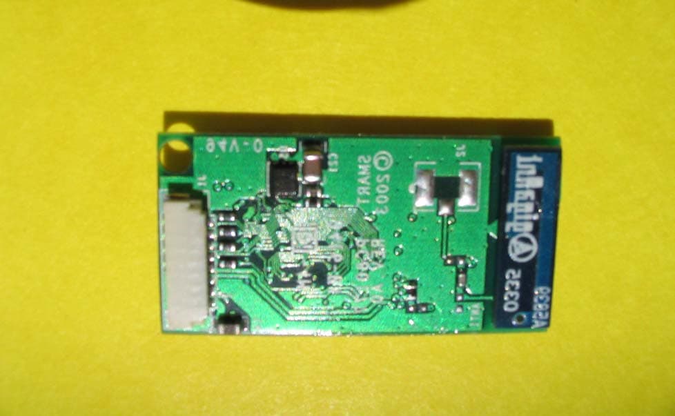
KOC-901773
Aug 19, 2004Bluetooth UART SPP Module
Equipment Class
DSS - Part 15 Spread Spectrum Transmitter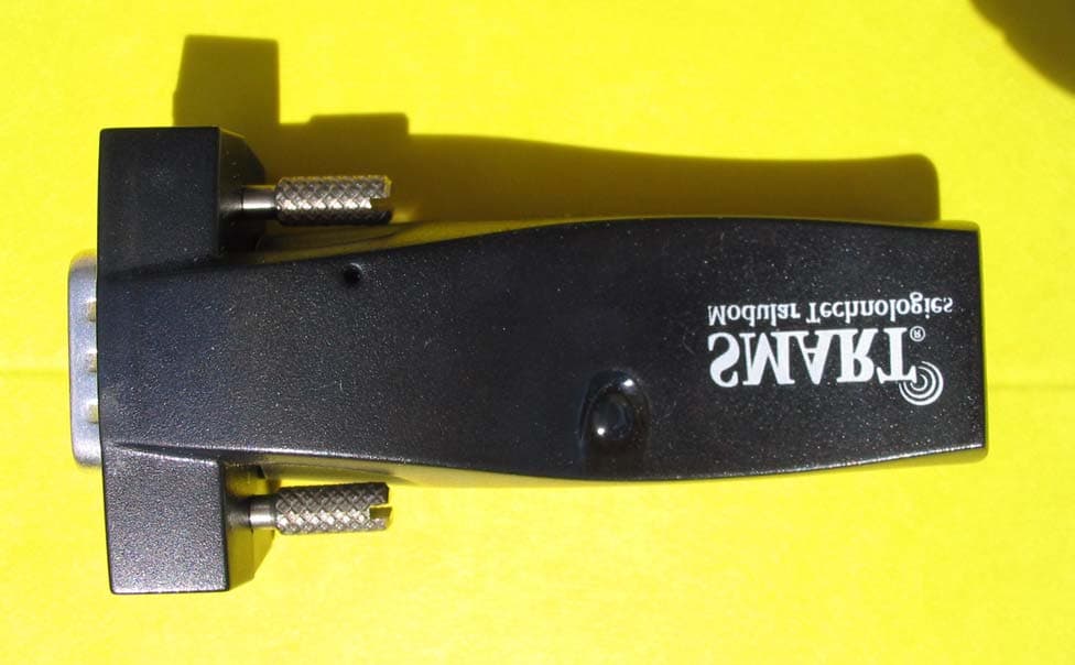
KOC-901781
Jul 04, 2004Bluetooth RS232 DCE adapter
Equipment Class
DSS - Part 15 Spread Spectrum Transmitter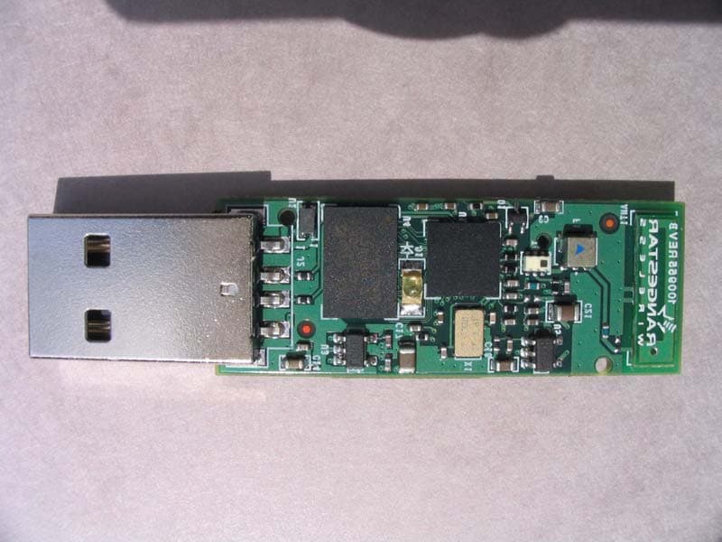
KOC-90183
Jun 10, 2004Bluetooth to USB bridge
Equipment Class
DSS - Part 15 Spread Spectrum Transmitter
KOC-100106
May 05, 2004Bluetooth Messaging Terminal
Equipment Class
DSS - Part 15 Spread Spectrum TransmitterKOC-90137
Jan 07, 2003USB Bluetooth Adapter
Equipment Class
DSS - Part 15 Spread Spectrum Transmitter