KQ9903Remote Eagle Module (REM) for radio telemetry
Sercel Inc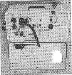
Click to zoom
Application Details
- Equipment Class
- TNB - Licensed Non-Broadcast Station Transmitter
- Date of Grant
- Aug 04, 2002
- Application Purpose
- Original Equipment
- Date of Application
- Aug 04, 2002
- Equipment Note
- Remote Eagle Module (REM) for radio telemetry
- Frequency Range
- 216.05000000 - 219.95000000
- Company
- Sercel Inc
- Country
- United States
Documents & Files
Document Text
Text extracted from the exhibit documents filed with the FCC. Open a document above to read the original.
Users Manual
Exhibit C-Operators Manual Installation Manual Description of the radio telemetry equipment Description of the radio telemetry equipment Remote Eagle Module (REM) The REM connects to the Left or Right Transverse connector of an LAUX, or a 408UL control module or another REM. It interfaces a radio cell with a wireline telemetry section or with the CM408 or 408XL. It is used to control the digitizer units (SU6-R) in a radio cell and retrieve the seismic data from it. 12 VDC XDEV Audio RF Power power supply output input to antenna Transverse connectors 12 VDC Multi-REM power supply output input Main specifications of the REM: · Operates from 12 VDC (a standard 12 V battery). · Data reception rate: 400 kbit/s. · 16 000 sample buffer per channel; acquisition capacity: 32 s@2 1T2S. · Transmit/receive frequencies: 216 to 230 MHz in 50-kHz steps; 0311400 8-3 Spectru m analyzer Description of the radio telemetry equipment l0 W RF output~ power (rain); One REM in each RF cell (1 retrieve frequency); Up to six REMs can be used on one antenna; Maximum number of REMs in a network: 16; Typical range: 16 to 24 km (10 to 15 miles). The REM has a built-in signal strength meter used to monitor the RF Spectrum on the HCI workstation, and an output for connection to an external spectrum analyzer with a finer resolution. The signal available on the Spectrum Analyzer output is picked up at the antenna with a 20 dB gain. Preamplifier If a preamplifier is used between the antenna and the Antenna connector on a REM, then the REM Layout Setup on the HCI workstation must let the REM supply a 12 V DC voltage to the preamplifier over the antenna downlead in receive mode. If any filter is used that does not relay DC voltage, then a DC Block must be used to supply power to the preamplifier. 8-4 March 2001 Installation Manual Description of the radio telemetry equipment SU6-R The SU6-R is a six-channel field digitizer unit used in radio telemetry cells. It uses a radio link to communicate with a REM. All the SU6-Rs are completely independent and can coyer any type of field. In the event of obstruction along an RF radio path to the REM, a simple wire telemetry link can be used in place of the RF link. The SU6-R uses a small, light-weight, ragged aluminum package for reliability and reduced transportation effort. Its main features are the following: · A rechargeable nickel-cadmium 0NJ-Cad) battery pack. · Analog-filter-free and ideal seismic response. Taking advantage of the large dynamic range and the very low distortion of the SU6-Rs 24-bit-stream A/D converter, the seismic channels are free from any analog filters. With this design, idem seismic response with linear phase shift is achieved, as undesirable phase shifts and temperature drifts otherwise associated with analog components are eliminated. Also, no filter setting is required at the field level, which precludes any unrecoverable error that might otherwise arise from incorrect filter settings. · A low distortion built-in test generator is integrated into every SU6-R, in order to performance a remote check of the complete acquisition performance, at full specification, from the central control unit without any external oscillator. · Internal memory that allows simultaneous collection and retrieval of seismic data. Shot stacking may also be performed by the SU6-R. · Each field unit is assigned to a specific frequency upon deployment by the control unit. NOTE: The SU6-R is fully compatible with SERCEL-OPSEIS SARs. 0311400 8-5 Installation Manual Description of the radio telemetry equipment FDPA (Field Deployment aid) The FDPA is a small hand-held terminal that allows you to program, monitor and test certain aspects of the setup for an SU6-R. Typically the checks are performed at the time of physical SU6-R deployment in order to speed up deployment. The FDPA activates the SU6-Rs power-up self-test, can evaluate cable leakage and continuity tests, and assign the SU6-R address and SU6-R wire-line function. The FDPA receives its power from the connected SU6-R. The test results are displayed on a 4-line, 20-column LCD screen. Multi-frequency RF Blaster The RF Blaster Unit, is a portable, internally battery- powered unit the shooter uses 'to initiate shot point operations. The RF Blaster sends and receives commands, and transmits data to the central control unit via its own RF transceiver. 0311400 8-7 Radio telemetry equipment (REM, SU6-R) Description of the radio telemetry equipment Battery charger It's a portable 8-hour charger designed to simultaneously charge 1 to 36 SU6-Rs. There are 6 charging cables. Each cable can charge up to six SU6-R units. LED circuits provide a visual indication of the charging process. Since each of the chargers is fully automatic, a battery can be connected to or disconnected from the charger independently of the others. A battery does not have to be fully discharged before it can be connected to the charger. Power Unit Capacity Tester. The Power Unit Capacity Tester (PUCT) can perform capacity testing on SU6-R Power Units to verify their performance before use on the field. It's basically a capacity tester with control circuitry to improve operation. It lets a user view the test and status results. The PUCT can also help rejuvenate battery packs suffering from "voltage depression". 8-8 March 2001 Radio telemetry equipment (REM, SU6-R) Connecting REMs Connecting REMs Minimum distance requirements In order not to overload the receiving stage in REMs and SU6-Rs, the following minimum distances are required: between REM and SU6-R: 100 m (300 ft); between REMs: 300 m (1000 ft); between SU6-Rs: 100 m (300 ft). These are approximate values, depending on the type and direction of the antenna and on various RF transmission parameters. 8-10 March 2001 Installation Manual Cab-mount aerial installation Compressor setting For in-depth information, please refer to the manufacturer's document. Before using the air compressor on the field, the primary …
Text truncated - open the document above for the full version.
Block Diagram
FCC ID KQ9903 Exhibit E- Block Diagram FCC ID KQ9903 Opseis Remote Eagle Module (REM) Block Diagram
Cover Letter(s)
FCC ID# KQ9903 Exhibit I- Agent Authorization Letter and Anti-Drug Statement) FCC ID# KQ9903
Cover Letter(s)
American Telecommunications Certification Body Inc. 6731 Whittier Ave, McLean, VA 22101 April 30, 2002 RE: FCC ID: KQ9903 I have a few comments on this Application. 1 External photos are used to give a clear view of the device and its’ operating control, switches and any external markings so an unambiguous identification of the device can be made in the application. The external photos provided do not give this clear identity. It is not clear if the photos provided appear to be showing the same devices. Please note the photos shown in exhibits D and H. while these appear to be the front panel of something, they do not appear to be the same something. Please provide external photos that show a clear an unambiguous identity of the device, its operator controls, switches etc. xx 2 The photo of the label is indistinguishable and not clear. Please note that photos are to be unambiguous and are to be identifiable. Please provide a clear drawing or photo of the FCC ID label. xx 3 No warnings to the installer/operator about MPE is provided. Please provide a statement to be included in the installation or operator’s manual warning installers and/or users of the potential MPE hazards. xx 4 Please note F1D is only a part of an Emissions Designator. The other part is the necessary bandwidth IAW 2.202 (i.e. 20K0, 400K, etc.). However, IAW 90.209 where the necessary BW is not easily obtainable, the occupied bandwidth can be used. The occupied Bandwidth from the report is 20KHz. This then could mean that the emissions designator might be 20K0F1D. Please provide/verify the complete emissions designator for this device including the calculated necessary or measured occupied bandwidth. xx 5 No manufacturers tune up procedure has been provided. Please provide the tune up procedure for this device. If one does not exist, please clarify how the manufacturer sets the power out of this device at the time of manufacture. 6 The application must reflect the actual measured power not the power listed in the manufacturers specifications. In this case it is 12.77 Watts. The grant would then say 13Watts. This is for your information only, no action need take place. If however, the manufacturer desires to have 15 watts listed on the grant then a device that conducts 15 watts to the antenna terminals needs to be tested. xx 7 Please note that the FCC specifies radiated spurious emissions for licensed devices are to be made using the antenna substitution method. TIA/EIA 603 is the accepted FCC procedure. Please provide antenna substitution data for radiated spurious emissions. xx Dennis Ward mailto:[email protected] The items indicated above must be submitted before processing can continue on the above referenced application. Failure to provide the requested information may result in application termination. Correspondence should be considered part of the permanent submission and may be viewed from the Internet after a Grant of Equipment Authorization is issued. Please do not respond to this correspondence using the email reply button. In order for your response to be processed expeditiously, you must submit your documents through the AmericanTCB.com website. Also, please note that partial responses increase processing time and should not be submitted. Any questions about the content of this correspondence should be directed to the sender.
Cover Letter(s)
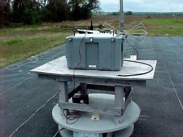
Subject: Sercel questions Date: Sun, 28 Jul 2002 23:27:18 -0500 From: "Brad Rehm" <[email protected]> To: <[email protected]> Dennis, Nicole brought a copy of your email to me a few minutes ago. I can answer both of the questions you ask, but you may want to suggest other ways of handling them. The RF exposure statement is at the end of Section 7 of the report. It reads: "Warning: Maximum Permissible Exposure to RF energy may be exceeded if the transmitter is activated while personnel are within two (2) meters of the antenna. Do not operate the transmitter while personnel are within two (2) meters of the antenna." You may already have seen this text, and you may be asking why it doesn't appear in the excerpts we've included of the manual. The reason is that although the new text has been added to the source version of the manual, the printed version isn't available yet. I can find out when this will be available if you need it. The tune-up procedure is in Appendix F. There is a reference to it at the end of Section 3: "To achieve this occupied bandwidth, the transmitter deviation is adjusted to 7 kHz. The manufacturing procedure used at Sercel is presented in Appendix D." As you can see, it is incorrectly labeled Appendix D. This is my fault, and I've corrected the error. The change will be in the final version of the report, which will also contain some text and the photograph of the equipment configuration on the OATS. Hope this helps. Brad [email protected] PTI
Cover Letter(s)
Subject: KQ9903 request for information Date: Tue, 09 Jul 2002 12:15:33 -0700 From: Dennis Ward <[email protected]> Organization: dt Associates To: Nicole Golden <[email protected]> > Hi Nicole I got a file from Brad Rehm on the above ID. He asked for a reference to TIA603-1 in CFR 47. I do not have brad's email address, so I would appreciate it if you could forward the following response on his question about antenna substitution measurements. HI Brad There is no direct reference to TIA/EIA603 in the CFR. However, what you do find in 2.947 (Measurement procedure) is: (a) The Commission will accept data which have been measured in accordance with the following standards or measurement procedures: (1) Those set forth in bulletins or reports prepared by the Commission's Office of Engineering and Technology. These will be issued as required, and specified in the particular part of the rules where applicable. (2) Those acceptable to the Commission and published by national engineering societies such as the Electronic Industries Association, the Institute of Electrical and Electronics Engineers, Inc., and the American National Standards Institute. (3) Any measurement procedure acceptable to the Commission may be used to prepare data demonstrating compliance with the requirements of this chapter. (b) Information submitted pursuant to paragraph (a) of this section shall completely identify the specific standard or measurement procedure used. (c) In the case of equipment requiring measurement procedures not specified in the references set forth in paragraphs (a)(1) and (2) of this section, the applicant shall submit a detailed description of the measurement procedures actually used. (d) A listing of the test equipment used shall be submitted. (e) If deemed necessary, the Commission may require additional information concerning the measurement procedures employed in obtaining the data submitted for equipment authorization purposes. The Office of Engineering and Technology has interpreted the above to mean that if a manufacturer uses a test method that is not known or readily accepted by the OET, that manufacturer must completely and fully explain how the measurements were made. If the manufacturer does not want to provide a full and detailed explanation, then they must use test methodologies that are accepted by the OET. These test methods being those produced by the recognized agencies (i.e. IEEE, ANSI, EIA, etc.) When the test methodology deals with a specific type of measurement (i.e. a specified ERP or EIRP measurements), the FCC does not accept other than the type measurements specified (i.e. ERP or EIRP) unless it can be shown by solid evidence that the levels are greater than 20 dB below the cited level. In the case of Part 90 and other licensed devices, both the FCC and TIA agree on how ERP or EIRP measurements are to be made. The OET has issued bulletins and other documentation (interpretations database) which provide guidance on what is an already acceptable test procedures for the various rule parts. In the FCC interpretation data base, the FCC states that the substitution method ALWAYS takes precedence over field strength measurements. It goes on to say that FOR CONSISTENCY, WE WANT EVERYONE TO USE THE SUBSTITUTION METHOD. The reason the request spoke to the substitution mehtod is that the report in question presents a single measured value and states that all other readings are more than 20dB below the cited level yet gives no evidence that this is the actual case. It states that spectrum analyzer plots of the spurious emissions is provided in figures 1, 2 and 3 in the appendix. However, no such appendix was provided, thus drawing question how verification of the statement is possible. Therefore, because no plots were provided as indicated, and because the substitution method always takes precedence, the request as stated in the document was made. In this case, even if antenna substitution is not used because levels are more than 20dB below the limit, it is good practice to show more than one reading as 'evidence' of compliance. Hope this helps.
External Photos
FCC ID# KQ9903 Exhibit H- External Photographs FCC ID# KQ9903 Opseis Remote Eagle Module (REM) External Photographs
ID Label/Location Info
Appendix B Equipment Label REM equipment label.
Internal Photos
______________________________________________________________________________________ Professional Testing (EMI), Inc. 1 Appendix C Photographs Photo 1. REM enclosure front view. ______________________________________________________________________________________ Professional Testing (EMI), Inc. 2 Photo 2. REM front panel. ______________________________________________________________________________________ Professional Testing (EMI), Inc. 3 Photo 3. Reference Oscillator, top view. Photo 4. Reference Oscillator, bottom view. ______________________________________________________________________________________ Professional Testing (EMI), Inc. 4 Photo 5. T/R Switch & Preamp, top view. Photo 6. T/R Switch & Preamp, bottom view. ______________________________________________________________________________________ Professional Testing (EMI), Inc. 5 Photo 7. T/R Switch Controller, top view. Photo 8. T/R Switch Controller, bottom view.
Internal Photos
______________________________________________________________________________________ Professional Testing (EMI), Inc. 1 Appendix C Photographs Photo 9. Transmit Interface, top view. Photo 10. Transmit Interface, bottom view. ______________________________________________________________________________________ Professional Testing (EMI), Inc. 2 Photo 11. Transmit Power Amp, top view. Photo 12. Transmit Power Amp, bottom view. ______________________________________________________________________________________ Professional Testing (EMI), Inc. 3 Photo 13. Transmit Power Control, top view. Photo 14. Transmit Power Control, bottom view. ______________________________________________________________________________________ Professional Testing (EMI), Inc. 4 Photo 15. Transmit Synthesizer, top view. Photo 16. Transmit Synthesizer, bottom view.
Operational Description
FCC ID KQ9903 Exhibit B- Operational Description FCC ID KQ9903 The Sercel Opseis Remote Eagle Module (REM) for radio telemetry Model 903 transceiver is a component in a seismic data-gathering system used in oil and natural gas exploration. In the field, such a system would include a portable seismic array of up to 1000 seismic sensors connected to 260 seismic acquisition remote units. The REM Model 903 receives data from other devices in the system and transmits this data in real-time or non-real-time to a Central Recording Station. The REM transmitter operates in the 216 to 220 MHz band, which is allocated for telemetering data. The operating frequency is determined by a synthesizer that references a temperature-compensated, 12.80 MHz crystal oscillator. The synthesizer operates under software control and is capable of changing the transmit frequency in 50 kHz steps. The system defaults to the factory pre-set 217.500 MHz on power-up. The user may select other operating frequencies using a local computer port. Operating frequencies may be set at intervals of 50 kHz, in the range, 216.050 to 219.950 MHz. The REM transmitter generates single-level FSK output using either Manchester or non-return-to-zero (NRZ) encoded FM. The data rate is 400 kilobits per second, resulting in a bit-rate frequency of 400 kHz. Transitions occur at least once per bit period. Peak deviation is 200 kHz, and the maximum output power is 15 Watts.
Parts List/Tune Up Info
FCC ID KQ9903 __________________________________________________________________________________ Professional Testing (EMI), Inc. 28 Appendix D Installation Manual Excerpts Sercel Opseis Remote Eagle Module (REM) for Radio Telemetry Excerpts from Installation Manual (Note: The User and Installation manuals for the REM and its associated components are lengthy documents and contain more information than is required in this report. For this reason, sections of the Installation Manual pertaining to the installation and operation of the REM have been excerpted for inclusion in this appendix.) FCC ID KQ9903 __________________________________________________________________________________ Professional Testing (EMI), Inc. 29 Installation Manual Description of the radio telemetry equipment FCC ID KQ9903 __________________________________________________________________________________ Professional Testing (EMI), Inc. 30 Description of the radio telemetry equipment Remote Eagle Module (REM) The REM connects to the Left or Right Transverse connector of an LAUX, or a 408UL control module or another REM. It interfaces a radio cell with a wireline telemetry section or with the CM408 or 408XL. It is used to control the digitizer units (SU6-R) in a radio cell and retrieve the seismic data from it. 12 VDC XDEV Audio RF Power power supply output input to antenna Transverse connectors 12 VDC Multi-REM power supply output/input Main specifications of the REM: · Operates from 12 VDC (a standard 12 V battery). · Data reception rate: 400 kbit/s. · 16 000 sample buffer per channel; acquisition capacity: 32 k. · Transmit/receive frequencies: 216 to 230 MHz in 50-kHz steps; 0311400 8-3 FCC ID KQ9903 __________________________________________________________________________________ Professional Testing (EMI), Inc. 31 Description of the radio telemetry equipment l0 W RF output~ power (rain); One REM in each RF cell (1 retrieve frequency); Up to six REMs can be used on one antenna; Maximum number of REMs in a network: 16; Typical range: 16 to 24 km (10 to 15 miles). The REM has a built-in signal strength meter used to monitor the RF Spectrum on the HCI workstation, and an output for connection to an external spectrum analyzer with a finer resolution. The signal available on the Spectrum Analyzer output is picked up at the antenna with a 20 dB gain. Preamplifier If a preamplifier is used between the antenna and the Antenna connector on a REM, then the REM Layout Setup on the HCI workstation must let the REM supply a 12 V DC voltage to the preamplifier over the antenna downlead in receive mode. If any filter is used that does not relay DC voltage, then a DC Block must be used to supply power to the preamplifier. 8-4 March 2001 FCC ID KQ9903 __________________________________________________________________________________ Professional Testing (EMI), Inc. 32 Installation Manual Description of the radio telemetry equipment SU6-R The SU6-R is a six-channel field digitizer unit used in radio telemetry cells. It uses a radio link to communicate with a REM. All the SU6-Rs are completely independent and can coyer any type of field. In the event of obstruction along an RF radio path to the REM, a simple wire telemetry link can be used in place of the RF link. The SU6-R uses a small, light-weight, ragged aluminum package for reliability and reduced transportation effort. Its main features are the following: · A rechargeable nickel-cadmium Ni-Cad) battery pack. · Analog-filter-free and ideal seismic response. Taking advantage of the large dynamic range and the very low distortion of the SU6-Rs 24-bit-stream A/D converter, the seismic channels are free from any analog filters. With this design, idem seismic response with linear phase shift is achieved, as undesirable phase shifts and temperature drifts otherwise associated with analog components are eliminated. Also, no filter setting is required at the field level, which precludes any unrecoverable error that might otherwise arise from incorrect filter settings. · A low distortion built-in test generator is integrated into every SU6-R, in order to performance a remote check of the complete acquisition performance, at full specification, from the central control unit without any external oscillator. · Internal memory that allows simultaneous collection and retrieval of seismic data. Shot stacking may also be performed by the SU6-R. · Each field unit is assigned to a specific frequency upon deployment by the control unit. NOTE: The SU6-R is fully compatible with SERCEL-OPSEIS SARs. 0311400 8-5 FCC ID KQ9903 __________________________________________________________________________________ Professional Testing (EMI), Inc. 33 FCC ID KQ9903 __________________________________________________________________________________ Professional Testing (EMI), Inc. 34 Installation Manual Description of the radio telemetry equipment FDPA (Field Deployment aid) The FDPA is a small hand-held terminal that allows you to program, monitor and test certain aspects of the setup for an SU6-R. Typically the checks are performed at the time of physical SU6-R deployment in order to speed up deployment. The FDPA activates the SU6-Rs power-up self-test, can evaluate cable leakage and continuity tests, and assign the SU6-R address and SU6-R wire-line function. The FDPA receives its power from the connected SU6-R. The test results are displayed on a 4-line, 20-column LCD screen. Multi-frequency RF Blaster The RF Blaster Unit, is a portable, internally battery- powered unit the shooter uses 'to initiate shot point operations. The RF Blaster sends and receives commands, and transmits data to the central control unit via its own RF transceiver. 0311400 8-7 FCC ID KQ9903 _________________________________________________________________________________ _Professional Testing (EMI), Inc. 35 Radio telemetry equipment (REM, SU6-R) Description of the radio telemetry equipment Battery charger It's a portable 8-hour ch…
Text truncated - open the document above for the full version.
Parts List/Tune Up Info
Professional Testing (EMI), Inc. Page 51 Appendix F Transmitter Deviation Alignment Procedure The following is excerpted from the Sercel document, “The Remote Eagle Module (REM) RF Modules/Boards Alignment Requirements and Test Procedure.” 2.1 REM TRANSMITTER ALIGNMENT (cont’d) 2.1.2 Deviation Adjustment 1. Cable equipment as shown in Figure 7-A. 2. Select REM Transmit on Module Type switch. 3. Select and load Frequency 11 (216.00 MHz). 4. With modulation select ON, adjust R13 to 7 kHz deviation. 5. Continue with loading selectable frequencies: 218.00 MHz 220.00 MHz 222.00 MHz 224.00 MHz 226.00 MHz 228.00 MHz NOTE: For each frequency selected, transmit to verify a 7 kHz deviation ±2 kHz.
Schematics
U2 22PF C2 2.2PF C3 22PF C5 36NH L1 36NH L2 .001 C6 51 R1 1.0UH L3 15PF C13 2.2PF C14 15PF C15 36NH L4 36NH L5 .001 C17 51 R3 1.0UH L6 .001 C22 22PF C27 36NH L7 36NH L8 15PF C28 115NH L9 115NH L10 68 R4 3.3K R5 1.8K R6 100 R7 68 R9 820 R8 .001UF C39 .1 C7 .1 C8 .1 C9 .001 C10 .001 C11 .001 C12 .1 C18 .1 C19 .001 C21 22PF C23 2.2PF C25 220PF C29 7PF C30 1500PF C32 0.1UF C33 .001 C34 .001UF C35 .001UF C36 18PF C37 39PF C38 0.1UF C40 47NH L11 1.0UH L12 1.0UH L13 Q1 1 3 42 100 R11 .1 C43 E6 E5 .001 C41 .001 C42 .1 C44 1.0UH L14 E3 E1 E4 U5U4 E7 E9 0.1UF C45 .01UF C46 .001UF C47 0.1UF C48 270PF C49 5600PF C50 270PF C51 6PFC52 270PF C53 1500PF C54 .01UF C55 .001UF C56 .001UF C57 0.1UF C58 270PF C59 5600PF C60 270PF C61 6PF C62 270PF C63 1500PF C64 115NH L15 115NH L16 115NH L17 115NH L18 115NH L19 115NH L20 4.7K R12 1.8K R13 SAT R14 100 R15 220 R16 4.7K R17 1.8K R18 330 R19 100 R20 220 R21 E8 E2 MMBTH10L Q2 2 1 3 MMBTH10L Q3 2 1 3 22PF C1 22PF C4 18PF C66 .001 C65 22PF C24 22PF C26 270PF C31 18 R10 .1 C20 56 R22 16.2 R2 18PF C16 U1 4-18-2000_15:0710151SCAB ASK-1 IF RF G G 6 5 43 2 1 LO G MSA-1105 4 1 3 2 MRF9411 INOUT LM78L82ACZ 2 3 GND 1 INOUT LM78L82ACZ 2 3 GND 1 INOUT LM78L82ACZ 2 3 GND 1 THIS DRAWING IS THE EXCLUSIVE PROPERTY OF SERCEL. REPRODUCTION AND UNAUTHORIZED USE ARE PROHIBITED. DATEAPPRV'DCHECKEDDRAWNACTIONREV REVISIONS SCALEDOC DESIGN DRAWN CHECKED APPROVEDREVDRAWING NO. TYPE SIZE C TITLE SCHEMATIC FILE SHEET A B D C A B C D 87654321 87654321 SERCEL INC. 1999 1 DATE MSA-1105 4 1 3 2 S. SMITH M.XieM.Xie AB U6 MICHAEL XIE MICHAEL XIE M.Xie DNA 1 U3 1 +8VR +8VR+8VR +12Vin+8VR LO in RF in +12V in +8VR +8VR R99038 1/17/00 1ST MIXER/1ST IF 2010151 REM RCVR, INPUT AMPLIFIER SC M.Xie 4/26/99 MICHAEL XIE 1/17/00 SCOTT SMITH 3/7/00 3/7/00 AA S. SMITH ABE10151AD 3/30/00 5V_SA ADC0 ADC1 ADC2 ADC3 ADC4 ADC5 ADC6 ADC7 _ADC_OE RF_D[7:0] RF_D7 RF_D6 RF_D4 RF_D3 RF_D2 RF_D1 RF_D0 RF_D7 RF_D6 RF_D4 RF_D3 RF_D2 RF_D1 RF_D0 RF_D7 RF_D6 RF_D5 RF_D4 RF_D3 RF_D2 RF_D1 RF_D0 RF_D7 RF_D6 RF_D5 RF_D4 RF_D3 RF_D2 RF_D1 RF_D0 RF_D5RF_D5 RSSI TP2 TP3 27PF C15 1 2 27PF C21 1 2 3.3UH L5 U8 1 2 3 4 8 7 6 5 150PF C18 1 2 R1/4W 332 R6 2 1 R1/4W 332 R7 2 1 0.1 C34 1 2 R1/4W 17.8 R5 21 47K R13 21 .001 C29 21 0.1 C31 1 2 U9 1 3 2 47K R12 21 62K R11 21 U9 7 5 6 TP1 33K R10 21 3900PF C27 1 2 0.5% 4.8K R17 2 1 0.5% 3.2K R16 2 1 1K R14 2 1 CR1 0.1 C30 1 2 U9 4 8 +5V +5V +5V +5V MH6 MH5 MH4 MH3 MH2 MH1 E1 E43 E23 E4 E22 E3 E21 E2 A0 D0 A1 D1 A2 D2 A3 D3 A4 D4 N0 D5 N1 D6 N2 D7 D8 D9 D10 D11 D12 D13 D14 D14 D13 D12 D11 D9 D15 D10 N3 D15 _SEISDAT E20 E33 E42 E37 E5 E19 E46 E30 E12 RX_DATA+ E11 E29 RX_CLK+ U6 7 3 5 18 2 6 4 _SEISCLK _RX_MSB _RX_LSB +5V +5V E15 E34 MH7 0.1 C6 1 2 +5V 1K R1 21 150PF C11 1 2 10.0K R2 21 U4 U1 10 201 11 129 138 147 156 165 174 183 192 U2 10 201 11 129 138 147 156 165 174 183 192 +5V U5 5 4 6 E7 E25 E48 E49 E50 0.1 C9 1 2 0.1 C4 1 2 0.1 C5 1 2 L6 U5 14 7 5600PF C28 1 2 SPREF E47 2_5V 1.5K R18 21 4.7 R8 2 1 0.1 C19 1 2 0.1 C10 1 2 150PF C22 1 2 0.5PF C20 1 2 4-18-2000_14:2010116SCAB U5 10 9 8 J1 RX_CLK- RX_DATA- E35 _ADC_WR U5 13 12 11 10_7MHZ .01 C14 21 150PF C16 1 2 22 C8 1 2 0.1 C12 1 2 C13 0.1 1 2 C1 0.1 21 C2 0.1 21 10K R4 2 1 470K R3 2 1 150PF C17 21 10K R15 2 1 3 +5V U7 4 6 2 81 5 3 7 0.1 C7 1 2 +5V +5V U5 2 1 3 0.1 C3 21 U3 10 201 11 129 138 147 156 165 174 183 192 0.1 C26 1 2 FLT2FLT1 6.2UH L1 6.2UH L2 AD8307 COM ENB INMINP INT OFS OUT VPS TLC27M2I - + TLC27M2I - + LM285-2-5 TLC27M2I VCC VEE LTC485 B DE GND R0VCC _RE A DI A_GND 8 CLK_IN 4 CLK_R 19 CS 1 DB0 18 DB1 17 DB2 16 DB3 15 DB4 14 DB5 13 DB6 12 DB7 11 D_GND 10 INTR 5 RD 2 VCC 20 VINN 7 VINP 6 VREF2 9 WR 3 ADC0802 D0Q0 D1Q1 D2Q2 D3Q3 D4Q4 D5Q5 D6Q6 D7Q7 CLK OEVCC GND 74HC574 D0Q0 D1Q1 D2Q2 D3Q3 D4Q4 D5Q5 D6Q6 D7Q7 CLK OEVCC GND 74HC574 74HCT132 FB 74HCT132 GND VCC THIS DRAWING IS THE EXCLUSIVE PROPERTY OF SERCEL. REPRODUCTION AND UNAUTHORIZED USE ARE PROHIBITED. DATEAPPRV'DCHECKEDDRAWNACTIONREV REVISIONS SCALEDOC DESIGN DRAWN CHECKED APPROVEDREVDRAWING NO. TYPE SIZE C TITLE SCHEMATIC FILE SHEET A B D C A B C D 87654321 87654321 SERCEL INC. 1999 1 DATE 74HCT132 COAX 74HCT132 + LTC485 B DE GND R0VCC _RE A DI 74HCT132 D0Q0 D1Q1 D2Q2 D3Q3 D4Q4 D5Q5 D6Q6 D7Q7 CLK OEVCC GND 74HC574 TE5140 2 COM 1 X1 3 X2 XTAL FILTER TE5140 2 COM 1 X1 3 X2 XTAL FILTER M. XIES. SMITH AB +5V AA D 6. C15 & C21 ARE TRIMMED WITH 1PF TO 4PF +SAT +SAT U6 & U7 ARE DRAWN USING NEGATIVE LOGIC 5. E38-40 & E44 ARE NOT USED 3. ALL CAPACITORS ARE IN MICROFARADS 2. ALL RESISTORS ARE IN OHMS NOTE: UNLESS OTHERWISE SPECIFIED 1 MICHAEL XIE 1NONE sc 1 PCA, SPECTRUM ANALY / INTRF BOARD REM 4. C20 IS NOT LOADED 2010116 R99038D. BELLS. SMITHM. XIE 3/6/00 07/26/99 07/26/99 RONNY LUMAN SCOTT SMITH MICHAEL XIE 2-3-00 3/6/00 ABE1011…
Text truncated - open the document above for the full version.
Contact Information
Applicant
Paul Wentzler(Vice President of Product Development)
Technical Contact
Professional Tesing (EMI), Inc.Brad Rhem
[email protected]512-244-3371
1601 FM 1460 Suite B · Round Rock, Texas · United States
Non-Technical Contact
Professional Tesing (EMI), Inc.Nicole Golden
[email protected]512-244-3371
Test Firm
Professional Testing (EMI), Inc.Jeff Link
Technical Specifications
| # | Rule Parts | Frequency Range | Power Output | Emission | Tolerance |
|---|---|---|---|---|---|
| 1 | 90.259 | 216.05 MHz - 219.95 MHz | 12.7 W | 20K0F1D | 50.0000000000 ppm |
Other Applications from Sercel Inc

KQ9-0A00A
Mar 17, 2024S-lynks node
Equipment Class
DTS - Digital Transmission System
KQ9-0800A
Mar 24, 2022Wireless seismic acquisition unit
Equipment Class
DTS - Digital Transmission System
KQ9-0500A
Oct 27, 2015WTU is a wireless seismic acquisition unit.
Equipment Class
DSS - Part 15 Spread Spectrum Transmitter
KQ9-0104A
Oct 04, 2015LRC is an Ethernet radio bridge
Equipment Class
DSS - Part 15 Spread Spectrum Transmitter
KQ9VIB-999
Aug 01, 2007Wireless acquisition unit for seismic data
Equipment Class
DTS - Digital Transmission System