KQ9LRU
Sercel Inc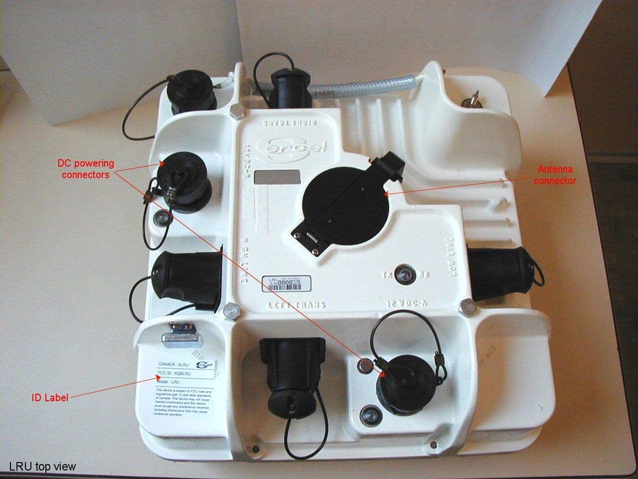
Click to zoom
Application Details
- Equipment Class
- TNB - Licensed Non-Broadcast Station Transmitter
- Date of Grant
- May 28, 2002
- Application Purpose
- Original Equipment
- Date of Application
- Apr 09, 2002
- Frequency Range
- 216.00000000 - 220.00000000
- Company
- Sercel Inc
- Country
- United States
Documents & Files
Document Text
Text extracted from the exhibit documents filed with the FCC. Open a document above to read the original.
Users Manual
March 2002 LRU User Manual In no event shall SERCEL be liable for incidental or consequential damages or related expenses resulting from the use of this product, or arising out of or related to this manual or the informa- tion contained in it, even if SERCEL has been advised, or knew or should have known of the possibility of such damages. The information included in this documentation is believed to be accurate and reliable. However, SERCEL reserves the right to make changes to its products or specifications at any time, without notice, in order to improve design or performance and to supply the best possible product. This documentation does not form in any way a contractual agreement of sales promise on the part of SERCEL. Software mentioned in this documentation is sold under a precise licence agreement and as such the documentation may cover technical areas for which the user may not have a final licence. No part of this documentation, or any of the information included herein may be modified or copied in any form or by any means without the prior written consent of SERCEL. Acknowledgments: All brand or product names are trademarks or registered trademarks of their respective companies or organizations. To contact SERCEL Nantes, France Commercial; Customer Support; Manufacturing & Repair. B.P. 439, 16 rue de Bel Air 44474 Carquefou Cedex Tel: +33 2 40 30 11 81, Fax: +33 2 40 30 19 48 Hot-Line: Land:+33 2 40 30 58 88 Marine: +33 2 40 30 59 59 E-mail:[email protected] [email protected] www.sercel.com St Gaudens, France Vibrator Customer Support; Vibrator Manufacturing & Repair; Streamer Manufacturing & Repair. Tel: +33 5 61 89 90 00, Fax: +33 5 61 89 90 45 Hot Line: +33 5 61 89 90 91 Alfreton, U. K. Streamer Manufacturing & Repair; Customer Support. Tel: +44 1 773 605 078, Fax: +44 1 773 541 778 Houston, USA Commercial; Customer Support; Manufacturing & Repair; Streamer Manufacturing & Repair. Tel: +1 281 492 66 88, Fax: +1 281 492 69 10 Hot-Line: +1 281 492 66 88 E-mail:[email protected] [email protected] [email protected] Ponca City, USA Vibrator Customer Support; Vibrator Manufacturing & Repair. Tel: +1 580 763 00 00, Fax: +1 580 763 00 22 Moscow, Russia Commercial; Customer Support. Tel: +7 095 254 06 59, Fax: +7 095 254 66 80 Beijing, P. R. of China Commercial; Customer Support. Tel: +86 106 43 76 661, Fax: +86 106 43 76 307 Tanggu, P. R. of China Manufacturing & Repair. Tel:+86 222 58 23 224 , Fax:+86 222 58 23 242 Xian, P. R. of China Manufacturing & Repair. Tel: +86 297 85 25 05, Fax: +86 297 85 55 04 Singapore Streamer Manufacturing & Repair; Customer Support. Tel:+65 545 0411, Fax:+65 545 1418 Dehradun, India Customer Support. Tel: +91 135 773 387, Fax: +91 135 773 132 E-mail: [email protected] LRU User Manual 1-1 General The LRU (Line Remote Unit) relay is a long range point-to-point radio relay cell that can be inserted anywhere in a spread as an element of the 408UL network to relay the data transmission on a Line or a Transverse. It connects to any type of 408UL field electronics (LAUX, LAUL, FDU Link, etc.). Built in the LRU is a full performance LAUX. In the LRU transmission protocol (Half-duplex), time is shared between transmission of Master-to-Slave messages and transmission of Slave- to-Master messages. Master-to-Slave messages are called Network Control Sequences (NCS), used for synchronization, zero-time transmission and control. Slave-to-Master messages are called Data Transfer Sequences (DTS), used for data retrieval, seismonitor and collecting test results. Typical setups 1-2 March 2002 Typical setups CAUTION If you wish to test a radio relay cell through a wireline link between the coaxial connectors of two LRUs, use a 60 dB (minimum), 20 W attenuator. 20 W 60 dB min. 12 V 12 V Attenuator (test setup) LRU 12 V LRU 12 V NO LRU 12 V LRU 12 V YES For optimal performance of the radio link, do not place any electric device (including LRU, FDPA408, etc.) on the same side as the radiating elements! Do not raise any antenna near electric power distribution lines! The antenna should be at the top the mast. 8 m Use the whole cable length to keep clear from the antenna. LRU User ManualTypical setups 1-3 CAUTION Antenna height is limited to 6.1 metre near airports. Below are typical examples of setups along with the associated specifications in terms of covered range and transmission capacity. Basic radio relay cell . Typical performance (Ground-Wave propagation above flat terrain): - Range: 24 km, 60 Ch @ 2 ms, Real time. - Range: 10 km, 240 Ch @ 2 ms, Real time. See CAUTION on page 1-2 . For the Left/Right and Low/High ports of the LRU, connect as usual (Left to Right; Low to High). LRU 12 V LAUX and Unit Transverse to Central radio functions Line or LRU 12 V Coax downlead 1 See below 7-element Yagi antenna Battery 1 Typical setups 1-4 March 2002 Radio relay in series connection To extend the relay range, you can use two relay cells in series connection as shown below. You can choose between two types of series setups, one with fewer antenna masts to raise, the other optimizing the data rate. • Two-mast series setup (high data rate) Typical performance of each relay cell (Ground-Wave propagation above flat terrain): - Range: 24 km, 60 Ch @ 2 ms, Real time. - Range: 10 km, 240 Ch @ 2 ms, Real time. Setups with more than two relay cells in series connection have not been tested yet. See CAUTION on page 1-2 . LRU 12 V Unit Transverse to Central Line or LRU 12 V 1 See below Battery LRU 12 V LRU 12 V 1 See below Requirements: - At least 300 m between antennas, - At least 13 MHz frequency separation. Transverse ports Line or For optimal performance, use vertical polar- ization in one cell and horizontal in the other. 1 LRU User ManualTypical setups 1-5 • Single-mast series setup Typical performance of each relay cell (in Ground-Wave propagation conditions above flat terrain): - Range: 24 km, 30 Ch @ 2 ms, Real time. - Range: 10 km, 120 Ch …
Text truncated - open the document above for the full version.
Users Manual
March 2002 LRU User Manual In no event shall SERCEL be liable for incidental or consequential damages or related expenses resulting from the use of this product, or arising out of or related to this manual or the informa- tion contained in it, even if SERCEL has been advised, or knew or should have known of the possibility of such damages. The information included in this documentation is believed to be accurate and reliable. However, SERCEL reserves the right to make changes to its products or specifications at any time, without notice, in order to improve design or performance and to supply the best possible product. This documentation does not form in any way a contractual agreement of sales promise on the part of SERCEL. Software mentioned in this documentation is sold under a precise licence agreement and as such the documentation may cover technical areas for which the user may not have a final licence. No part of this documentation, or any of the information included herein may be modified or copied in any form or by any means without the prior written consent of SERCEL. Acknowledgments: All brand or product names are trademarks or registered trademarks of their respective companies or organizations. To contact SERCEL Nantes, France Commercial; Customer Support; Manufacturing & Repair. B.P. 439, 16 rue de Bel Air 44474 Carquefou Cedex Tel: +33 2 40 30 11 81, Fax: +33 2 40 30 19 48 Hot-Line: Land:+33 2 40 30 58 88 Marine: +33 2 40 30 59 59 E-mail:[email protected] [email protected] www.sercel.com St Gaudens, France Vibrator Customer Support; Vibrator Manufacturing & Repair; Streamer Manufacturing & Repair. Tel: +33 5 61 89 90 00, Fax: +33 5 61 89 90 45 Hot Line: +33 5 61 89 90 91 Alfreton, U. K. Streamer Manufacturing & Repair; Customer Support. Tel: +44 1 773 605 078, Fax: +44 1 773 541 778 Houston, USA Commercial; Customer Support; Manufacturing & Repair; Streamer Manufacturing & Repair. Tel: +1 281 492 66 88, Fax: +1 281 492 69 10 Hot-Line: +1 281 492 66 88 E-mail:[email protected] [email protected] [email protected] Ponca City, USA Vibrator Customer Support; Vibrator Manufacturing & Repair. Tel: +1 580 763 00 00, Fax: +1 580 763 00 22 Moscow, Russia Commercial; Customer Support. Tel: +7 095 254 06 59, Fax: +7 095 254 66 80 Beijing, P. R. of China Commercial; Customer Support. Tel: +86 106 43 76 661, Fax: +86 106 43 76 307 Tanggu, P. R. of China Manufacturing & Repair. Tel:+86 222 58 23 224 , Fax:+86 222 58 23 242 Xian, P. R. of China Manufacturing & Repair. Tel: +86 297 85 25 05, Fax: +86 297 85 55 04 Singapore Streamer Manufacturing & Repair; Customer Support. Tel:+65 545 0411, Fax:+65 545 1418 Dehradun, India Customer Support. Tel: +91 135 773 387, Fax: +91 135 773 132 E-mail: [email protected] LRU User Manual 1-1 General The LRU (Line Remote Unit) relay is a long range point-to-point radio relay cell that can be inserted anywhere in a spread as an element of the 408UL network to relay the data transmission on a Line or a Transverse. It connects to any type of 408UL field electronics (LAUX, LAUL, FDU Link, etc.). Built in the LRU is a full performance LAUX. In the LRU transmission protocol (Half-duplex), time is shared between transmission of Master-to-Slave messages and transmission of Slave- to-Master messages. Master-to-Slave messages are called Network Control Sequences (NCS), used for synchronization, zero-time transmission and control. Slave-to-Master messages are called Data Transfer Sequences (DTS), used for data retrieval, seismonitor and collecting test results. Typical setups 1-2 March 2002 Typical setups CAUTION If you wish to test a radio relay cell through a wireline link between the coaxial connectors of two LRUs, use a 60 dB (minimum), 20 W attenuator. 20 W 60 dB min. 12 V 12 V Attenuator (test setup) LRU 12 V LRU 12 V NO LRU 12 V LRU 12 V YES For optimal performance of the radio link, do not place any electric device (including LRU, FDPA408, etc.) on the same side as the radiating elements! Do not raise any antenna near electric power distribution lines! The antenna should be at the top the mast. 8 m Use the whole cable length to keep clear from the antenna. LRU User ManualTypical setups 1-3 CAUTION Antenna height is limited to 6.1 metre near airports. Below are typical examples of setups along with the associated specifications in terms of covered range and transmission capacity. Basic radio relay cell . Typical performance (Ground-Wave propagation above flat terrain): - Range: 24 km, 60 Ch @ 2 ms, Real time. - Range: 10 km, 240 Ch @ 2 ms, Real time. See CAUTION on page 1-2 . For the Left/Right and Low/High ports of the LRU, connect as usual (Left to Right; Low to High). LRU 12 V LAUX and Unit Transverse to Central radio functions Line or LRU 12 V Coax downlead 1 See below 7-element Yagi antenna Battery 1 Typical setups 1-4 March 2002 Radio relay in series connection To extend the relay range, you can use two relay cells in series connection as shown below. You can choose between two types of series setups, one with fewer antenna masts to raise, the other optimizing the data rate. • Two-mast series setup (high data rate) Typical performance of each relay cell (Ground-Wave propagation above flat terrain): - Range: 24 km, 60 Ch @ 2 ms, Real time. - Range: 10 km, 240 Ch @ 2 ms, Real time. Setups with more than two relay cells in series connection have not been tested yet. See CAUTION on page 1-2 . LRU 12 V Unit Transverse to Central Line or LRU 12 V 1 See below Battery LRU 12 V LRU 12 V 1 See below Requirements: - At least 300 m between antennas, - At least 13 MHz frequency separation. Transverse ports Line or For optimal performance, use vertical polar- ization in one cell and horizontal in the other. 1 LRU User ManualTypical setups 1-5 • Single-mast series setup Typical performance of each relay cell (in Ground-Wave propagation conditions above flat terrain): - Range: 24 km, 30 Ch @ 2 ms, Real time. - Range: 10 km, 120 Ch …
Text truncated - open the document above for the full version.
ID Label/Location Info
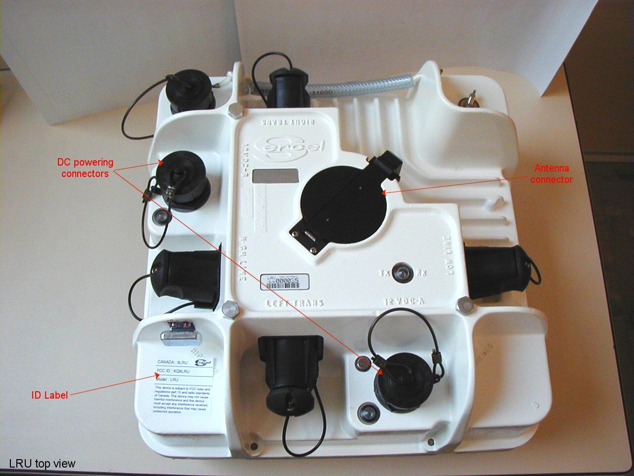
CANADA : 9LRU FCC ID : KQ9LRU Model : LRU This device is subject to FCC rules and regulations part 15 and radio standards of Canada. This device may not cause harmful interference and this device must accept any interference received, including interference that may cause undesired operation
Operational Description
March 2002 LRU Operational description In no event shall SERCEL be liable for incidental or consequential damages or related expenses resulting from the use of this product, or arising out of or related to this manual or the informa- tion contained in it, even if SERCEL has been advised, or knew or should have known of the possibility of such damages. The information included in this documentation is believed to be accurate and reliable. However, SERCEL reserves the right to make changes to its products or specifications at any time, without notice, in order to improve design or performance and to supply the best possible product. This documentation does not form in any way a contractual agreement of sales promise on the part of SERCEL. Software mentioned in this documentation is sold under a precise licence agreement and as such the documentation may cover technical areas for which the user may not have a final licence. No part of this documentation, or any of the information included herein may be modified or copied in any form or by any means without the prior written consent of SERCEL. Acknowledgments: All brand or product names are trademarks or registered trademarks of their respective companies or organizations. To contact SERCEL Nantes, France Commercial; Customer Support; Manufacturing & Repair. B.P. 439, 16 rue de Bel Air 44474 Carquefou Cedex Tel: +33 2 40 30 11 81, Fax: +33 2 40 30 19 48 Hot-Line: Land:+33 2 40 30 58 88 Marine: +33 2 40 30 59 59 E-mail:[email protected] [email protected] www.sercel.com St Gaudens, France Vibrator Customer Support; Vibrator Manufacturing & Repair; Streamer Manufacturing & Repair. Tel: +33 5 61 89 90 00, Fax: +33 5 61 89 90 45 Hot Line: +33 5 61 89 90 91 Alfreton, U. K. Streamer Manufacturing & Repair; Customer Support. Tel: +44 1 773 605 078, Fax: +44 1 773 541 778 Houston, USA Commercial; Customer Support; Manufacturing & Repair; Streamer Manufacturing & Repair. Tel: +1 281 492 66 88, Fax: +1 281 492 69 10 Hot-Line: +1 281 492 66 88 E-mail:[email protected] [email protected] [email protected] Ponca City, USA Vibrator Customer Support; Vibrator Manufacturing & Repair. Tel: +1 580 763 00 00, Fax: +1 580 763 00 22 Moscow, Russia Commercial; Customer Support. Tel: +7 095 254 06 59, Fax: +7 095 254 66 80 Beijing, P. R. of China Commercial; Customer Support. Tel: +86 106 43 76 661, Fax: +86 106 43 76 307 Tanggu, P. R. of China Manufacturing & Repair. Tel:+86 222 58 23 224 , Fax:+86 222 58 23 242 Xian, P. R. of China Manufacturing & Repair. Tel: +86 297 85 25 05, Fax: +86 297 85 55 04 Singapore Streamer Manufacturing & Repair; Customer Support. Tel:+65 545 0411, Fax:+65 545 1418 Dehradun, India Customer Support. Tel: +91 135 773 387, Fax: +91 135 773 132 E-mail: [email protected] LRU operational descriptionDescription of the LRU relay 1-1 Description of the LRU relay The LRU relay operates within the frequency band from 215 MHz to 250 MHz. Within that band, it uses a minimum 200-kHz bandwidth, on one or two channels, each with a 800-kHz maximum bandwidth, depending on the selected data rate. The user is responsible for inquiring about local radio frequency regulations and using the frequency band accordingly. The LRU unit operates from a 10.5 VDC to 15.0 VDC power supply voltage. The power supply should be capable of generating a minimum current of 15 A. A 12 VDC battery can be used as a power supply. The power supply used shall be compliant with the rules and regulations of the FCC, of Canada or with other local regulations. The antenna impedance to be used is 50 Ohm. The maximum VSWR is 1.7:1 at the operating frequencies. The allowable temperature range for both operating and storage is -40°C to +70°C. The LRU unit comes with standard 408UL Transverse, Line, Power and XDEV connectors. The Type-N, radio connector is waterproof when connected. Attention should be paid to put the cap in place on the radio connector whenever the unit is not in use, in order to keep the connector clean and the unit waterproof. The LRU relay is a half-duplex transmission system. With "Field ON" activated in the Line main window on the HCI, the unit connected to the side towards the Central Unit continuously transmits a time tick signal (every 50 ms) that allows the other end to keep clock-synchronized. Supplied along with each LRU relay are two 7-elements antennas and two 6- to 8-m telescopic portable masts. Description of the LRU relay 1-2 March 2002 7-element Yagi antenna 6- to 8-m telescopic portable mast (less than 20 kg) Low Line High Line Right Trans Left Trans Tx Rx XDEV 12 VDC A 12 VDC B GND 12 V LRU operational descriptionTheory of operation 1-3 Theory of operation The LRU relay uses a half-duplex transmission protocol. Half-duplex In the LRU transmission protocol, time is shared between transmission of Master-to-Slave messages and transmission of Slave-to-Master messages. Master-to-Slave messages are called Network Control Sequences ( NCS ), used for synchronization, zero-time transmission and control. Slave-to-Master messages are called Data Transfer Sequences ( DTS ), used for data retrieval, seismonitor and collecting test results. Typically, NCS messages are transmitted every 50 ms. In reply to an NCS message, the Slave LRU transmits a DTS message. LRU LRU DTS NCS (Master) (Slave) NCSDTSNCSDTS (50 ms) (50 ms) Radio frame time Theory of operation 1-4 March 2002 LRU frequency management The RF transceiver in the LRU unit uses a single 2-MHz band for both transmission and reception. That band is selected between 216 MHz and 249 MHz using the “Center Frequency” parameter. Within the 2-MHz bandwidth, you can choose which channel(s) to use for NCS and DTS messages, by specifying: •a Control Channel Frequency for NCS messages, •a Data Channel Frequency for DTS messages. The necessary bandwidth for a Data Channel depends on the expected Data Rate (256, 512, 1024 or 2048 kbps). See the diagram on page 7-5 . The RF transmission i…
Text truncated - open the document above for the full version.
Test Report
5.0 - ELECTROMAGNETIC COMPATIBILITY TEST DATA 5.1 - General Electromagnetic compatibility testing is divided into sections, as follows: a) HP141T Spectrum Analyzer Detector, b) IFR Spectrum Aalyzer c) Site Calibration d) Receiver Tests e) Transmitter Tests 1) Antenna Conducted Spurious Emissions a 2) Case Radiated Spurious Emissions Measurements were made from 30 Mhz to 40 Ghz on the receiver and transmitter, using an IFR A-7550 Spectrum Analyzer, SN 2347 and an HP141T Spectrum Analyzer, SN 2205A21383 with calibrated mixers. The IFR A-7550 was used for measurements below 1000 Mhz. 5.2 - Hewlett Packard 141 T Spectrum Analyzer Detecter The HP141T Spectrum Analyzer system 3 Db IF bandwidth or resolution bandwidth was set to 10 Khz for all measurements. The FCC requires a bandwidth of 4 Khz. Therefore the observed data is 10 log (10/4) = 4.0 Db too high. The noise bandwidth, for the HP141T system, as defined by Hewlett Packard Application Note 150-4, April 1974, is 1.2 times the three Db bandwidth. Therefore the observed data is an additional 10 log (1.2) = 0.8 Db too high. From the previously mentioned application note it is stated that "the detected signal is smaller than its true rms value. This correction for the log display mode combined with the detector characteristics gives a total correction of 2.5 Db, which should be added to any random noise measured in the log display mode. " The summation of corrections is as follows: - 4.0 Db Bandwidth - 0.8 Db Noise bandwidth + 2.5 Db Detector characteristics - 2.3 Db Total The observed power levels are therefore 2.3 Db too high for noise or noise like random signals, for the HP analyzer. 5.3 - IFR A7550 Spectrum Analyzer Detectors For site calibration data from 30 - 1000 Mhz the peak detector was utilized, 200 Khz resolution bandwidth. The guidelines for Verification are set by the American National Standards Institute (ANSI)in C63.4-1992. These guidelines were originally set by the Comite International Special Pertubations Radioelectroniques (CISPR) and call for quasi-peak detection. On the A7550 Quasi-Peak measurements is valid only in the Linear Mode, with proper bandwidth. The quasi-peak detector utilized had a bandwidth of 120 Khz. The signal amplitude (in dbuv) is calculated from the formula A = T + X where: A = value in dbuv T = top of scale X = value from table, attached In conformance with the operating manual the A7550 was first used with the EUT turned off to null out the ambient spectrum. The ambient spectrum was nulled in steps of 30-100, 100 –200, 200-300 Mhz etc, as well as first looking at the entire band. We then stored the trace and subtracted it from the spectrum with the EUT on. Quasi-peak measurements were then made. KQ9LRU REQUEST FOR CERTIFICATION FIGURE 3 - MODULATION TEST SETUP ...................... .................... . IFR A-7550 . ..... . . . ANALYZER . ..... ...... EUT . . . ..... . . ...................... 30 dB .................... EASY-SPAN SOFTWARE ATTENUATOR . .................... . MODULATION SOURCE. .................... . . ..................... . HP141 T ANALYZER . . SYSTEM . ..................... 5.4 - OATS Size & Location The OATS measured 8.5 meters by 14.6 meters. The OATS was constructed on a plywood platform, covered by a metal ground plane. It was located in a field adjacent to the Sercel Cable Manufacturing Plant. Sercel has three facilities on Park Row, in Houston, Texas. The coordinates, as taken by a Differential GPS and referenced to NAD83, were: 40:25:19.9 North Latitude by 086:52:19.1 West Longitude. Dates of testing were March 09, 10, 12, 13 & 14, 15 th, 2002. Hours of testing were 6:30 AM to 6:30 PM. We chose to work on Saturday and Sunday as rain was forecasted and did occur on Monday. The temperature at the site was roughly 62 degrees Fahrenheit/ 16.7 degrees Centigrade throughout the test period. 5.41 OATS Calibration Test Procedure Two Bicon Log Periodic Antennas were utilized. One an Emco 3143 calibrated to 1.7 Ghz by Emco. The second antenna was also a Bicon Log Periodic built by Antenna Research, model LPB 2520/A, rented from Teology. We picked up the EMCO 3143, 2075-2 motorized mast and 2090 Fiber-optic Controller at EMCO in Texas and drove to the site. The 2075-2 and 2090 were rented from EMCO. Three meter separation was kept between the centerline of the two antennas. The mutal impedance correction factors for broadband antennas equals zero. Attenuators were not found to be necessary to minimize cable reflections. In actuality we would have had to borrow coaxial attenuators because United Parcel Service (UPS) temporarily misplaced our tray of coaxial attenuators. We decided to try it without and found we were able to achieve the desired results. A Marconi 2022E Signal generator was utilized to feed the Antenna Research LPB 2520/A Bicon Log Peridic Antenna. This antenna was kept at a fixed height of 2 meters above the ground plane for the Horizontal Polarization, while the receive antenna was scanned from 1 to 4 meters in height, at three meters center - center of the two antennas. For Vertical Polarization the antenna was kept 1.0 meters off the ground plane while the receive antenna was varied from 1 to 4 meters in height. The equation used to calculate values was: An = Vdirect - Vsite - TXfactor - RXfactor where: An = Normalized Site Attenuation (db) Vdirect = reading with the two cables disconnected from the antenna and connected to each other via an adapter, in this case male to male type N. Vsite = reading re-connected to their respective antennas and with the receive antenna scanned in height from 1-4 meters, maximum reading recorded. Txfactor = Transmit Antenna Factor Rxfactor = Receive Antenna Factor Pictures of the OATS are attached as well as calibration data. PHOTO 3 TEST SITE CALIBRATION PHOTO PHOTO 4 PICTURE OF TEST SITE TAKEN FROM A DISTANCE Power Lines 65 Feet from Edge 5.5 - Receiver Emissions Verification Verification was performed on the receiver at 3 meters r…
Text truncated - open the document above for the full version.
Test Report
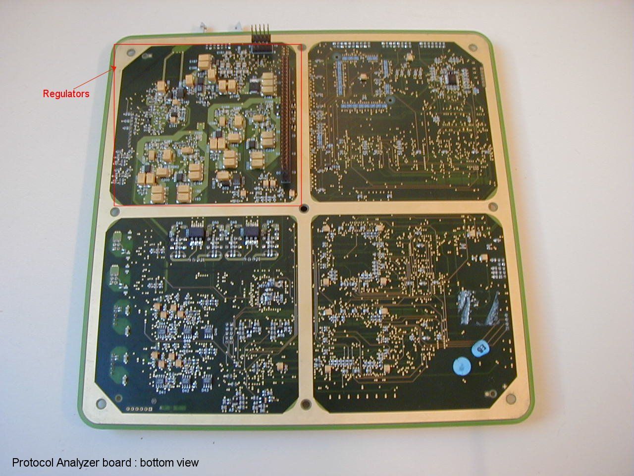
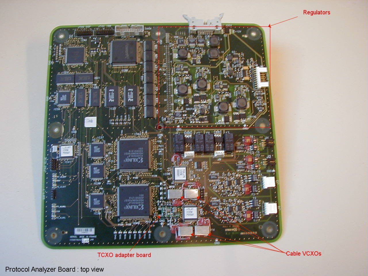
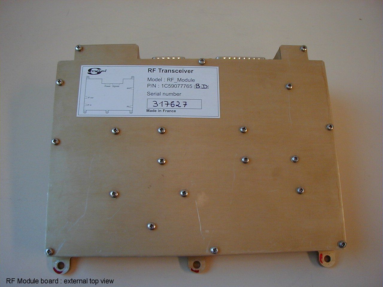
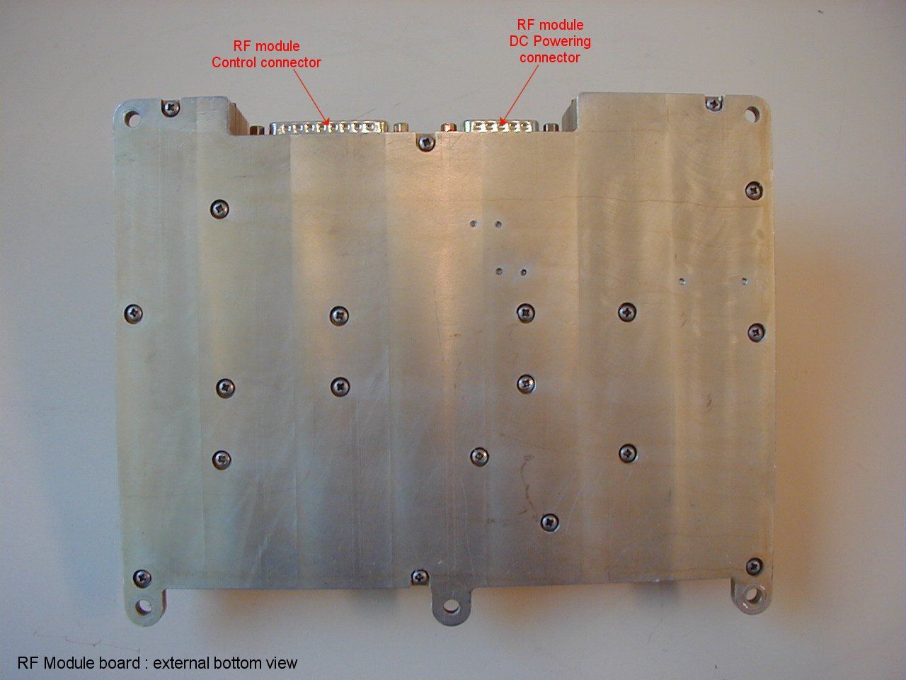
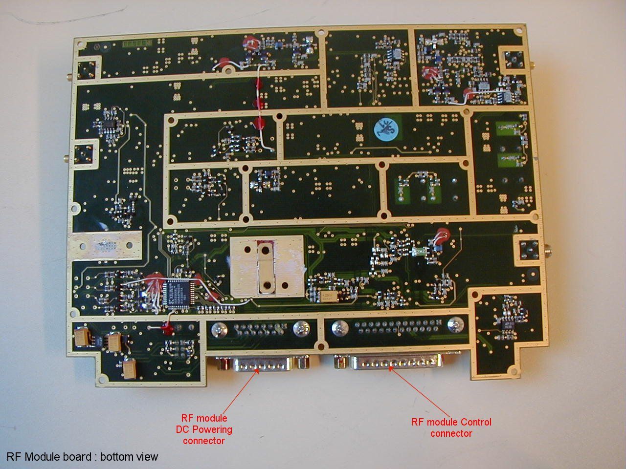
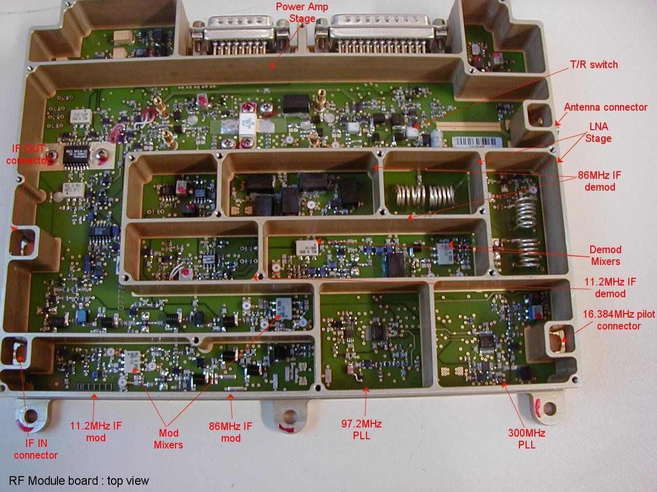
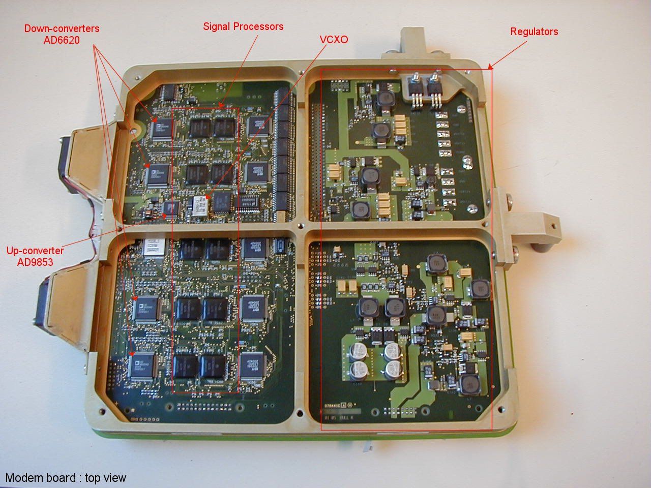
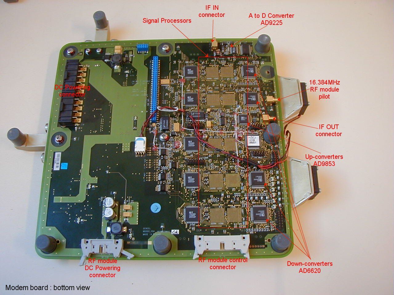
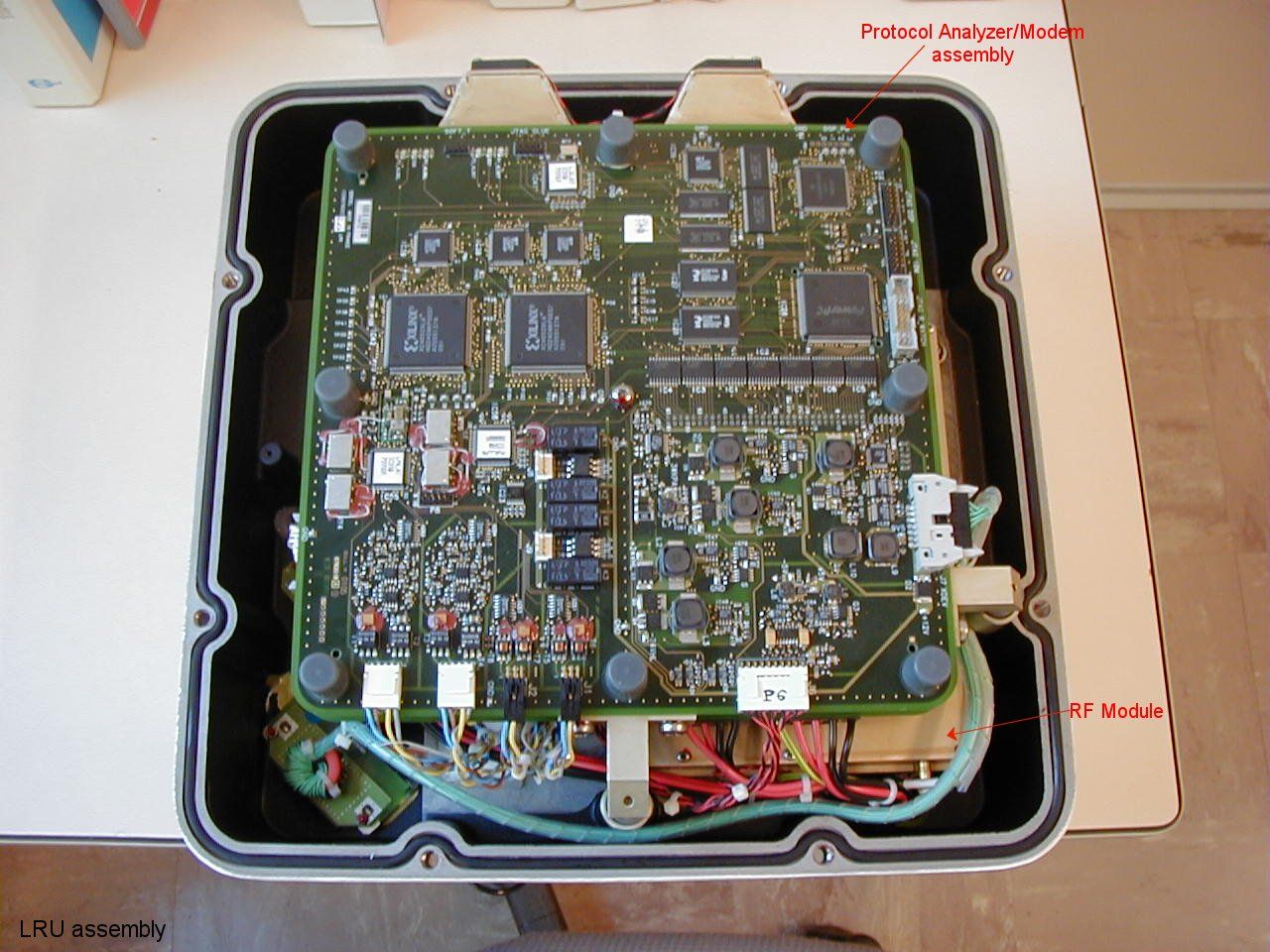
TEST REPORT KQ9LRU REQUEST FOR CERTIFICATION AND VERIFICATION DATA SUBMITTED BY: CONSOLIDATED SPECTRUM SERVICES 22 MERRILL DRIVE ATKINSON, NH 03811 ON BEHALF OF: SERCEL INC. 17200 PARK ROW HOUSTON, TEXAS 77084 1.0 - GENERAL INFORMATION 1.1 - Company Information SERCEL INC. is a well recognized leader in the oil and natural gas exploration markets. SERCEL INC is based in France with additional manufacturing and business headquarters in the State of Texas. The product herein described is set for a particular frequency of operation by country code at the factory. 1.2 - Description of Equipment Tested The KQ9LRU, also referred to as EUT, is used to measure geological characteristics that lie beneath the earth or ocean floor. It is used in cable and wireless applications. The unit is waterproof. The EUT consists of three main sections, which are: a) A protocol analyzer b) Modem or Mod/Demod Board c) RF Module The EUT in transmit mode, develops 6.0 Watts,nominal. It transmits in very short bursts during normal operation. It is typically polled from a central site. The KQ9LRU has data storage capability in its receiver section. It can also be used as a central unit or as a relay for a group of units. The EUT, is powered by a 12 V DC deep cycle marine battery source as provided by others. The EUT is intended for operation by prospective licensees in the 216 to 220 Mhz band, under FCC rule part 90.259. Operation is on a secondary basis to the maritime mobile and federal government services. 1.3 - FCC Rule Parts and Standards The EUT falls under FCC rule parts 2, 15 and 90. FCC rule part 90.203 (a) requires the EUT to meet the Certification process, for the transmit portion. In addition since the receiver operates between 30 and 960 Mhz and the transmitter is subject to certification, FCC rule part 15.101 (b) applies. This section requires the receiver portion to be subject to the verification process. FCC rule part 15.3 (k) defines digital devices and unintentional radiators. It states in part, "a radio frequency device that is specifically subject to an emanation requirement in any other rule part or an intentional radiator subject to subpart C of this part that contains a digital device is not subject to the standards for digital devices, provided that the digital device is used only to enable operation of the radio frequency device and the digital device does not control additional functions or capabilities." FCC rule part 2.1057 (a) (1) specifies the measurement range over which harmonics are to be measured for equipment operating below 10 Ghz. It states in part "to the tenth harmonic of the highest fundamental frequency or to 40 Ghz, whichever is lower." This unit has a fundamental frequency of 220 Mhz maximum. The highest oscillator in the unit operates at 336 Mhz. If we use the oscillator as the highest frequency, 10 times this would be 3360 Mhz. We measured to 40 Ghz for the Verification and Certification process, well exceeding the FCC specification. 1.4 - Technical Information The following tests and measurements were performed in the engineering laboratories of Sercel Inc., with the exception of Electromagnetic Compatibility Testing, which was recorded on a characterized open area test site, herein referred to as OATS. All equipment utilized was calibrated with an accuracy traceable to the National Bureau of Standards and American National Standards Institute (ANSI). All tests were performed under the direction of Howard Epstein of Consolidated Spectrum Services. We had two people from our company at the site, myself and an employee. 1.5 - Equipment Utilized A List of Equipment used for the tests is contained below along with the calibration due dates. DESCRIPTION CALIBRATION DUE KQ9LRU S/N 000022 PRODUCTION UNIT N/A HP5313A FREQUENCY COUNTER 08/08/2002 HP778D DUAL DIRECTIONAL COUPLER, 20 DB 03/01/2003 HP435A POWER METER 05/21/2002 WITH HP8481A SENSOR LAMBDA DC VARIABLE POWER SUPPLY 05/21/2002 WEINSCHEL 30 DB 25 W COXIAL ATTENUUATOR 08/08/2002 WEINSCHEL 10 DB 25 W COXIAL ATTENUUATOR 08/08/2002 TENNEY TTC TEST CHAMBER 02/02/2003 EMCO 2075-2 MINI-MAST 02/21/2003 EMCO 2090 CONTROLLER 02/21/2003 IFR A7550 SPECTRUM ANALYZER 02/24/2003 HP141T, 8552, 8555 SPECTRUM ANALYZER 12/27/2002 HP11517A EXTERNAL MIXER 08/21/2002 EMCO 3143 BICON LOG PERIODIC ANTENNA 02/26/2003 CALIBRATED BY EMCO TO 1.7 Ghz ANTENNA RESEARCH LPB 2520/A BICON LOG 12/19/2002 PERIODIC ANTENNA EMPIRE SYSTEMS APN101 LOG PERIODIC ANTENNA 03/04/2003 MR STANDARD GAIN HORN ANTENNA 03/04/2005 WAVELINE 799 HORN ANTENNA 03/04/2005 WAVELINE 1099 HORN ANTENNA 03/04/2005 NARDA 56K1 HORN ANTENNA 03/04/2005 MARCONI 2022E SIGNAL GENERATOR 03/04/2003 SERCEL DESIGN FLUSH CONDUCTIVE TURNTABLE 03/04/2003 WOOD TRIPOD N/A LOW PASS FILTERS 03/04/2005 HIGH PASS FILTERS 03/04/2005 2.0 - TEST DATA The Test Data is divided into sections, as follows: a) Environmental, b) Modulation Characteristics and c) Electromagnetic Compatibility. For those portions of the test dealing with the transmitter the EUT was operated in the transmit mode one hundred (100) percent of the time. For those portions of the test dealing with the receiver the EUT was operated in the receive mode one hundred (100) percent of the time. 3.1 ENVIRONMENTAL 3.2 - General Pursuant to FCC rule parts 2 and 90 the EUT was subjected to environmental testing. these tests are subdivided into two sections, as follows: a) RF Output Power Stability and b) Frequency Stability For the EUT, the temperature range over which testing occurred was -30 to +55 degrees Celsius. This range was spanned in increments of 10 degrees or less. The voltage was varied from 10.2 to 13.8 V DC, which are considered to be the batt…
Text truncated - open the document above for the full version.
Contact Information
Applicant
Paul Wentzler(Vice President of Product Development)
Technical Contact
Consolidated Spectrum ServicesHoward R Epstein
[email protected]603-362-5977
22 Merrill Drive · Atkinson, New Hampshire · United States
Non-Technical Contact
Consolidated Spectrum ServicesHoward R Epstein
[email protected]603-362-5977
Technical Specifications
| # | Rule Parts | Frequency Range | Power Output | Emission | Tolerance |
|---|---|---|---|---|---|
| 2 | 90.259 | 216 MHz - 220 MHz | 6 W | 800KD1D | 2.5 ppm |
Other Applications from Sercel Inc

KQ9-0A00A
Mar 17, 2024S-lynks node
Equipment Class
DTS - Digital Transmission System
KQ9-0800A
Mar 24, 2022Wireless seismic acquisition unit
Equipment Class
DTS - Digital Transmission System
KQ9-0500A
Oct 27, 2015WTU is a wireless seismic acquisition unit.
Equipment Class
DSS - Part 15 Spread Spectrum Transmitter
KQ9-0104A
Oct 04, 2015LRC is an Ethernet radio bridge
Equipment Class
DSS - Part 15 Spread Spectrum Transmitter
KQ9VIB-999
Aug 01, 2007Wireless acquisition unit for seismic data
Equipment Class
DTS - Digital Transmission System