KUTPS10XMotion Sensor
Capital Prospect Ltd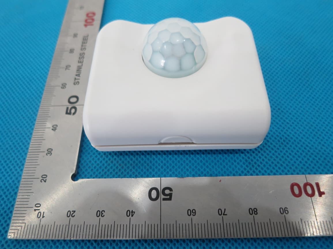
Click to zoom
Application Details
- Equipment Class
- DSC - Part 15 Security/Remote Control Transmitter
- Date of Grant
- Sep 09, 2014
- Application Purpose
- Original Equipment
- Date of Application
- Sep 09, 2014
- Equipment Note
- Motion Sensor
- Frequency Range
- 433.90000000 - 433.90000000
- Company
- Capital Prospect Ltd
- Country
- Hong Kong
Documents & Files
Document Text
Text extracted from the exhibit documents filed with the FCC. Open a document above to read the original.
Users Manual
MOTION SENSOR Model PS-MT FCC ID: KUTPS10X 1. INTRODUCTION The motion sensor model PS-MT is designed to monitor movement around your house. Once motion is detected, the receiver will beep and flash. In this package, you should find a motion sensor and mounting accessories. Please follow the instructions below to setup the motion sensor. 2. INSTALLATION i) Remove the back cover on the motion sensor and insert one AA battery (not included) to the sensor as shown in the diagram. ii) After inserting the battery to the motion sensor and its LED will be on for 2 seconds. The motion sensor requires a warm up time of approx. 30 seconds before it can function properly. After powering up the motion sensor, face it to the wall where no motion will be detected. iii) After 30 seconds, the motion sensor is ready. Press and hold the learn button in the receiver unit, release the button when the receiver emits a beep. Select the zone location in the receiver, press the zone button [1 or 2 or 3 or 4] once on the receiver unit. The corresponding zone red LED on the receiver will flash. iv) Wave your hand or walk in front of the motion sensor, the receiver will emit a beep and the corresponding red LED on the receiver will stop flashing indicating it has learned the code from the sensor. MOUNTING LOCATION Mount the motion sensor on the wall or ceiling with screws or double sided tape provided. WALK TEST After mounting the sensor at the desired location, it is important to perform a walk test in order to determine if the sensor is detecting the things you want to detect. You should walk in the area that you would like the sensor to monitor. The receiver will beep if the sensor detects your movement. If the receiver does not respond, adjust the mounting accordingly. Perform the walk test again after 20 seconds. Repeat this procedure until your motion is detected. There should be no movement in the detected area during the 20 seconds. Perform walk test in the undesired area to ensure movement cannot be detected. Tips: The sensor should not face towards direct sunlight, placing near heat or clod producing devices (i.e. A/C or furnace vents, fans, ovens, heaters etc) that may cause false triggers. OPERATION When motion is detected in the monitored area, the motion sensor will send a signal to the receiver. It will beep and the corresponding zone red LED light will flash. FCC This device complies with Part 15 of the FCC Rules. Operation is subject to the following two conditions: (1) This device may not cause harmful interference, and (2) This device must accept any interference received, including interference that may cause undesired operation. Warning: Changes or modifications to this unit not expressly approved by the party responsible for compliance could void the user’s authority to operate the equipment. WARRANTY If, within one year from date of purchase, this product should become defective (except battery), due to faulty workmanship or materials, it will be repaired or replaced, without charge. Proof of purchase and a Return Authorization are required. CUSTOMER SERVICE If you would like to order Skylink’s products or have difficulty getting them to work or download information and user manual, please: 1. visit our FAQ section at www.skylinkhome.com, or 2. email us at [email protected], or 3. call our toll free at 1-800-304-1187 from Monday to Friday, 9 am to 5 pm EST. 17 Sheard Avenue, Brampton, Ontario, Canada L6Y 1J3 ©2014 SKYLINK GROUP This device complies with Industry Canada licence-exempt RSS standard(s). Operation is subject to the following tow conditions: (1)this device may not cause interference, and(2) this device must accept any interference, includinginterference that may cause undesired operation of the device. Le présent appareil est conforme aux CNR d'Industrie Canada applicables auxappareils radio exempts de licence. L'exploitation est autorisée aux deux conditions suivantes :(1) l'appareil ne doit pas produire de brouillage, et(2) l'utilisateur de l'appareil doit accepter tout brouillage radioélectrique subi, même si le brouillage est susceptible d'en compromettre lefonctionnement.
Cover Letter(s)
Aug. 12, 2014 Federal Communication Commission Authorization and Evaluation Division FCC ID: KUTPS10X Re: Confidentiality Request Pursuant to Sections 0.457 and 0.459 of the Commission’s Rules, the applicant hereby requests confidential treatment of information applied this application as outlined below: 1: Block Diagram 2: Circuit Diagram 3: Operational Description 4: Parts List The above materials contain trade secrets and proprietary information not customarily released to the public. The public disclosure of these matters might be harmful to the applicant and provide unjustified benefits to its competitors. The Applicant understands that pursuant to Rules 0.457, disclosure of this Application and all accompanying documentation will not be made before the date of the Grant for this application. Sincerely, Capital Prospect Ltd. Contact person: Joe Ng Title: Project Manager
External Photos
External Photos TOP VIEW OF EUT BOTTOM VIEW OF EUT FRONT VIEW OF EUT BACK VIEW OF EUT LEFT VIEW OF EUT RIGHT VIEW OF EUT
ID Label/Location Info
FCC ID Label Location Model: PS-MT FCC ID: KUTPS10X
Internal Photos
Internal Photos OPEN VIEW OF EUT-1 OPEN VIEW OF EUT-2 INTERNAL VIEW OF EUT-1 INTERNAL VIEW OF EUT-2 INTERNAL VIEW OF EUT-3
Test Report
Report No.: AGC01585140702FE03 Page 1 of 29 FCC Test Report Report No.: AGC01585140702FE03 FCC ID : KUTPS10X APPLICATION PURPOSE : Original Equipment PRODUCT DESIGNATION : Motion Sensor BRAND NAME : Skylink MODEL NAME : PS-MT CLIENT : Capital Prospect Ltd. DATE OF ISSUE : Aug.07, 2014 STANDARD(S) : FCC Part 15 Rules REPORT VERSION : V1.0 Attestation of Global Compliance (Shenzhen) Co., Ltd CAUTION: This report shall not be reproduced except in full without the written permission of the test laboratory and shall not be quoted out of context. Report No.: AGC01585140702FE03 Page 2 of 29 Report Revise Record Report Version Revise Time Issued Date Valid Version Notes V1.0 / July.08, 2014 Valid Original Report Report No.: AGC01585140702FE03 Page 3 of 29 TABLE OF CONTENTS 1. VERIFICATION OF CONFORMITY ...................................................................................... 4 2. GENERAL INFORMATION .................................................................................................. 5 2.1. PRODUCT DESCRIPTION ........................................................................................................ 5 2.2. RELATED SUBMITTAL(S) / GRANT (S) .................................................................................... 5 2.3. TEST METHODOLOGY ............................................................................................................. 5 2.4. SPECIAL ACCESSORIES ......................................................................................................... 5 2.5. EQUIPMENT MODIFICATIONS ................................................................................................. 5 3. MEASUREMENT UNCERTAINTY........................................................................................ 6 4. DESCRIPTION OF TEST MODES........................................................................................ 6 5. SYSTEM TEST CONFIGURATION ...................................................................................... 6 5.1. EQUIPMENT USED IN EUT SYSTEM ....................................................................................... 6 5.2. SUMMARY OF TEST RESULTS ................................................................................................ 6 6. TEST FACILITY .................................................................................................................... 7 7. ANTENNA REQUIREMENT ................................................................................................. 8 8. PROVISION FOR MOMENTARY OPERATION ................................................................... 9 8.1 MEASUREMENT PROCEDURE ................................................................................................. 9 8.2 TEST SETUP .............................................................................................................................. 9 8.3 TEST RESULT .......................................................................................................................... 10 9. Duty Cycle Correction factor ............................................................................................ 11 9.1 MEASUREMENT PROCEDURE ................................................................................................ 11 9.2 TEST SETUP ............................................................................................................................. 11 9.3 TEST RESULT .......................................................................................................................... 12 10. RADIATED EMISSION ..................................................................................................... 14 10.1. MEASUREMENT PROCEDURE ............................................................................................ 14 10.2. TEST SETUP ......................................................................................................................... 16 10.3. TEST RESULT ....................................................................................................................... 17 11. BANDWIDTH .................................................................................................................... 22 11.1. MEASUREMENT PROCEDURE ............................................................................................ 22 11.2. TEST SETUP ......................................................................................................................... 22 11.3. TEST RESULT ....................................................................................................................... 23 APPENDIX A: PHOTOGRAPHS OF TEST SETUP ............................................................... 24 APPENDIX B: PHOTOGRAPHS OF EUT .............................................................................. 25 Report No.: AGC01585140702FE03 Page 4 of 29 1. VERIFICATION OF CONFORMITY Applicant Capital Prospect Ltd. Address 1303,Blk B,Veristrong Ind center,36 Apuiwan Street,Fotan,HK Manufacturer Capital Prospect Ltd. Address 1303,Blk B,Veristrong Ind center,36 Apuiwan Street,Fotan,HK Product Designation Motion Sensor Brand Name Skylink Test Model: PS-MT Date of test Aug.04, 2014 to Aug.06, 2014 Deviation None Condition of Test Sample Normal Report Template AGCRT-US-BR/RF (2013-03-01) We hereby certify that: The above equipment was tested by Attestation of Global Compliance (Shenzhen) Co., Ltd. The test data, data evaluation, test procedures, and equipment configurations shown in this report were made in accordance with the procedures given in ANSI C63.4 (2003) and the energy emitted by the sample EUT tested as described in this report is in compliance with radiated emission limits of FCC Rules Part 15.231. Prepared By Freddie Duan Aug.07, 2014 Checked By Kidd Yang Aug.07, 2014 Authorized By Solger Zhang Aug.07, 2014 Report No.: AGC01585140702FE03 Page 5 of 29 2. GENERAL INFORMATION 2.1. PRODUCT DESCRIP…
Text truncated - open the document above for the full version.
Test Setup Photos
Test Setup Photos FCC RADIATED EMISSION TEST SETUP
Contact Information
Applicant
Joe Ng(Project Manager)
Test Firm
Attestation of Global Compliance Shenzhen Co. Ltd.Forrest Lei
Technical Specifications
| # | Rule Parts | Frequency Range | Power Output |
|---|---|---|---|
| 1 | 15.231 | 433.9 MHz - 433.9 MHz | - |
Other Applications from Capital Prospect Ltd

KUTSM001
Jun 25, 2023Side Mount Garage Door Opener
Equipment Class
DXX - Part 15 Low Power Communication Device Transmitter
KUT2NV9
Feb 19, 2020Garage Door Controller Mini Nova Hub
Equipment Class
DXT - Part 15 Low Power Transceiver, Rx Verified
KUTMKA315
Aug 27, 2014315MHz remote control
Equipment Class
DSC - Part 15 Security/Remote Control Transmitter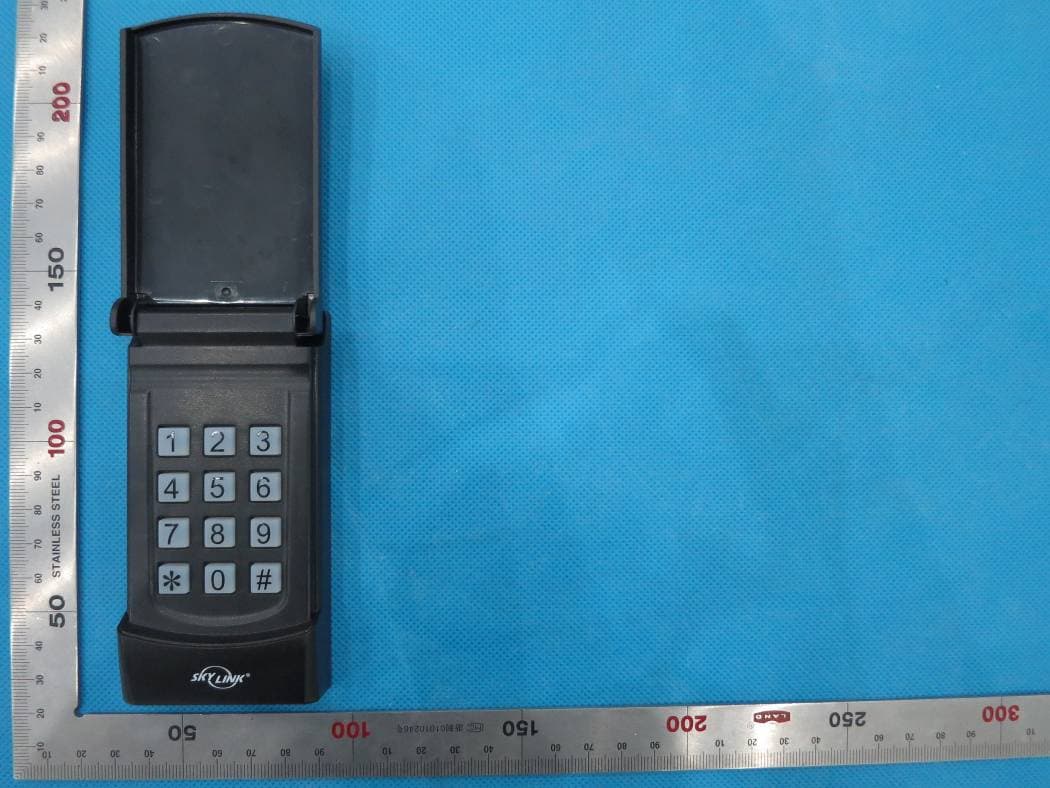
KUTKN103
Jul 16, 2014Wireless keypad
Equipment Class
DSC - Part 15 Security/Remote Control Transmitter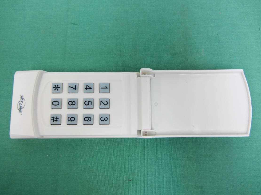
KUTKN318
Nov 27, 2013Wireless Keypad
Equipment Class
DSC - Part 15 Security/Remote Control Transmitter