KUW800BDADownlink Booster
Andrew Corporation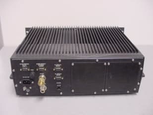
Click to zoom
Application Details
- Equipment Class
- TNB - Licensed Non-Broadcast Station Transmitter
- Date of Grant
- Dec 12, 2006
- Application Purpose
- Original Equipment
- Date of Application
- Dec 12, 2006
- Equipment Note
- Downlink Booster
- Frequency Range
- 866.00000000 - 869.00000000
- Company
- Andrew Corporation
- Country
- United States
Documents & Files
Document Text
Text extracted from the exhibit documents filed with the FCC. Open a document above to read the original.
Users Manual
Wireless Innovations Group 2601 Telecom Parkway Richardson, Texas 75082 400/800 MHz Fiber Optic & RF Fed Bi-Directional Amplifier Operations / Maintenance Manual DWG NO: Error! Not a valid link. Rev: Error! Not a valid link. Date :06/16/2004 Page: 1 of 63 OPERATIONS / MAINTENANCE MANUAL For 400MHz Fiber Optic Fed & RF Fed Bi-Directional Amplifier AE04A-D1248-001 AE04A-D1246-001 800MHz Fiber Optic Fed & RF Fed Bi-Directional Amplifier AE04A-D1437-001 AE04A-D1436-001 MANUAL NO. AE04B-A1669 REVISION A The information set forth in this document and all rights in and to inventions disclosed herein, and patents that might be granted thereon disclosing, employing or covering the materials, methods, techniques or apparatus described herein are the exclusive property of Andrew Corporation. This document is an operation and maintenance manual. No disclosure or reproduction of the information or drawings shall be made of any other purpose without the prior written consent of Andrew Corporation. Use of the information contained herein to fabricate or assemble any item in whole or in part is expressly prohibited. Wireless Innovations Group 2601 Telecom Parkway Richardson, Texas 75082 400/800 MHz Fiber Optic & RF Fed Bi-Directional Amplifier Operations / Maintenance Manual DWG NO: Error! Not a valid link. Rev: Error! Not a valid link. Date :06/16/2004 Page: 2 of 63 Table of Contents INTRODUCTION ..................................................................................................................................... 5 Scope.........................................................................................................................................................................5 Purpose.....................................................................................................................................................................5 GLOSSARY OF TERMS................................................................................................................................6 1.0 SAFETY CONSIDERATIONS ..................................................................................................... 7 1.1 Electric Shock Hazard ...............................................................................................................................7 1.2 Hot Surface Hazard ...................................................................................................................................7 1.3 Optical Laser Hazard ................................................................................................................................7 1.4 Emergency Contact Numbers ...................................................................................................................7 2.0 EQUIPMENT OVERVIEW / DESCRIPTION ........................................................................... 8 3.0 SPECIFICATION .......................................................................................................................... 8 3.1 Parts Lists ...................................................................................................................................................9 3.1.1 400 MHz Bi-Directional Amplifier....................................................................................................9 3.1.2 800 MHz Bi-Directional Amplifier ....................................................................................................9 3.2 Electrical Specifications .............................................................................................................................9 3.2.1 400 MHz Bi-Directional Amplifier Downlink Specification............................................................9 3.2.2 400 MHz Bi-Directional Amplifier Uplink Specification ...............................................................10 3.2.3 800 MHz Bi-Directional Amplifier Downlink Specification..........................................................10 3.2.4 800 MHz Bi-directional Amplifier Uplink Specification...............................................................11 3.3 Mechanical Specifications........................................................................................................................11 3.4 Environmental Specifications..................................................................................................................12 4.0 EQUIPMENT PHOTOGRAPHS ................................................................................................ 12 4.1 400 MHz Fiber Optic Fed Bi-Directional Amplifier ..................................................................................12 4.2 800 MHz Fiber Optic Fed Bi-Directional Amplifier ..................................................................................13 5.0 MODULES .................................................................................................................................... 14 5.1 400 MHz EO Cell Amplifier Module (AE04A-D1264-001) ..................................................................14 5.1.1 Description....................................................................................................................................14 5.1.2 Specification..................................................................................................................................15 5.1.3 Photographs ..................................................................................................................................15 5.1.4 Schematics.....................................................................................Error! Bookmark not defined. 5.2 480 MHz High Isolation Duplexer (AE04A-D1442-001) ......................................................................26 5.2.1 Description ....................................................................................................................................26 5.2.2 Specification...…
Text truncated - open the document above for the full version.
Block Diagram
RF to Fiber Converter Amplifier Stage #1 Amplifier Stage #2 Amplifier Stage #3 Fiber to RF Converter ALC Coupler RF Out Fiber RF In Downlink Block Diagram RF to Fiber Converter Amplifier Stage #1 Amplifier Stage #2 Amplifier Stage #3 Fiber to RF Converter Coupler RF In Fiber RF Out Uplink Block Diagram
Cover Letter(s)
November 6, 2006 Nemko Canada Inc 303 River Road Ottawa, Ontario, Canada K1V 1H2 Attn: Director of Certification Authority to Act as Agent - FCC On our behalf, I appoint Nemko Dallas to act as our agent in the preparation of this application for equipment certification. I certify that submitted documents properly describe the device or system for which equipment certification is sought. I also certify that each unit manufactured, imported or marketed, as defined in the Federal Communications Commission’s regulations will have affixed to it a label identical to that submitted for approval with this application. For instances where our authorized agent signs the application for certification on our behalf, I acknowledge that all responsibility for complying with the terms and conditions for certification, as specified by Nemko Canada Inc, still resides with Andrew Corporation, 2601 Telecom Parkway, Richardson, TX 75082. Dated this 6th Day of November 20 06 Agency agreement expiration date: May 6, 2007 By: Dana Collins Signature Printed Title: Senior Program Manager On behalf of : Andrew Corporation Telephone: 972-952-0002
External Photos
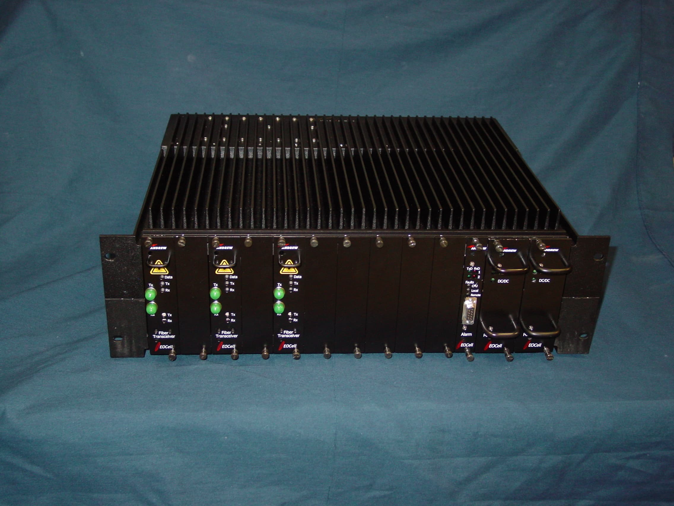
800 MHz Fiber Optic Fed Bi-Directional Amplifier
Internal Photos
800 MHz Amplifier Module - Top 800 MHz Amplifier Module - Bottom Fibre Optic Control Module Top Fibre Optic Control Module Bottom Power Supply Module - Top Power Supply Module – Bottom Alarm Module - Top Alarm Module - Bottom
Operational Description
EQUIPMENT OVERVIEW / DESCRIPTION MBTA System Wide Radio Tunnel Antenna Distribution System provides extended radio coverage within MBTA rail transit tunnels. The new tunnel antenna system is a two-way communication system consisting of 400 MHz base transceiver stations, 800 MHz base transceiver stations, antennas, radiating cable, fiber optic cable and BDAs. Both the 400 MHz and 800 MHz systems operate independently. The 400 MHz system operate as a conventional analog voice communication system and the 800 MHz system operate as a digital trunked radio system for voice and data communications. Radio signals routed from the base transceiver stations to the BDAs are performed via fiber optic cable. Once the optical signal is received by the BDA, it is converted back into an electrical (RF) signal, amplified and transmitted throughout the tunnel antenna distribution system. For RF signals transmitted within the tunnel, they are received by the BDA, amplified, converted into a optical signal and sent via fiber cable to the base transceiver stations. Each BDA is designed for a 19” rack mount cabinet and is equipped with interchangeable modules. These modules are field replaceable by removing them from the front chassis of the BDA. The modules consist of a downlink amplifier, uplink amplifier, high isolation duplexer, low isolation duplexer (400 MHz RF fed BDA only), fiber optic transceiver (fiber fed BDA only) and a AC to DC power supply. and alarm module (Optional Equipment). All BDA controls are performed via a RS232 connector located on the front panel of each amplifier module. Each BDA has 30 dB of gain adjustment for both the uplink and downlink RF path. This adjustment is varied electronically thru the amplifier modules’ front panel RS232 connector. Additionally, each of the amplifier modules are equipped with an Automatic Level Control (ALC) circuit which can limit the maximum power level produced by the BDA. OPTIONAL EQUIPMENT (Not Used By MBTA) An alarm module is available as an option to serve as a central communication agent to monitor the status of each module and send a summary alarm to remote locations via the fiber optic transceiver module. SPECIFICATION Parts Lists 400 MHz Bi-Directional Amplifier Andrew Part Number Description Qty. Section AE04A-D1264-001 400 MHz EO Cell Amplifier Module 2 5.1 AE04A-D1442-001 480 MHz High Isolation Duplexer 1 5.2 AE04A-D1443-001 480 MHz Low Isolation Duplexer 1 1 5.3 AE04A-D1100-009 Fiber Optic Transceiver Module 1 5.6 AE04A-D0803-002 +48V Power Supply Module 1 5.7 AE04A-D0805-007 Alarm Module (Optional Equipment) 1 5.8 1.Used in RF Fed BDA. 800 MHz Bi-Directional Amplifier Andrew Part Number Description Qty. Section AE04A-D1265-001 800 MHz EO Cell Amplifier Module 2 5.4 AE04A-D1438-001 800 MHz High Isolation Duplexer 1 1 5.5 AE04A-D1100-009 Fiber Optic Transceiver Module 1 5.6 AE04A-D0803-002 +48V Power Supply Module 1 5.7 AE04A-D0805-007 Alarm Module (Optional Equipment) 1 5.8 1.Two units required for RF Fed BDA. Electrical Specifications 400 MHz Bi-Directional Amplifier Downlink Specification PARAMETER DOWNLINK SPECIFICATION Operating Frequency Range 483.1625 – 483.2375 MHz Pass Bandwidth 75 kHz Gain Typical 48 dB Output Gain Adjustment 1 30 dB Power Output @ 4 Carriers +19.0 dBm/C Composite Output Power +30 dBm max. Composite Input Power -18 dBm max. Impedance 50 Ohms VSWR 2:1 OIP3 2 +44 dBm Noise Power max. @ 48dB Gain -64 dBm/Hz (-110 dBm/Hz; RF Fed BDA) AC Power 120 VAC Single Phase Notes: 1.Via Front Panel RS232 Connector. 2. Two-Tone Intermodulation: Measured two-output carriers at +20.0 dBm/C (+19.0 dBm/C for RF Fed BDA) at 483.1625 MHz and 483.2375 MHz with a BDA gain setting of 48 dB. 400 MHz Bi-Directional Amplifier Uplink Specification PARAMETER UPLINK SPECIFICATION Operating Frequency Range 486.1625 – 486.2375 MHz Pass Bandwidth 75 kHz Gain Typical 48 dB Output Gain Adjustment 1 30 dB Composite Output Power +5 dBm max. Composite Input Power (With ALC Activated) -14 dBm max. Impedance 50 Ohms VSWR 2:1 OIP3 2 + 26 dBm (+44 dBm; RF Fed BDA) Noise Power max. @ 48 dB Gain -110 dBm/Hz AC Power 120 VAC Single Phase Notes: 1.Via Front Panel RS232 Connector. 2. Two-Tone Intermodulation: Measured two-input carriers at – 48 dBm/C (-30 dBm/C for RF Fed BDA) at 486.1625 MHz and 486.2375 MHz with a BDA gain setting of 48 dB. 800 MHz Bi-Directional Amplifier Downlink Specification PARAMETER DOWNLINK SPECIFICATION Operating Frequency Range 866 – 869 MHz Pass Bandwidth 3 MHz Gain Typical 48 dB Output Gain Adjustment 1 30 dB Power Output @ 16 Carriers +11.1 dBm/C Power Output @ 8 Carriers +16.8 dBm/C Composite Output Power +30 dBm max. Composite Input Power -18 dBm max. Impedance 50 Ohms VSWR 2:1 OIP3 2 +44 dBm Noise Power max. @ 48dB Gain -64 dBm/Hz (-110 dBm/Hz; RF Fed BDA) AC Power 120 VAC Single Phase Notes: 1.Via Front Panel RS232 Connector. 2. Two-Tone Intermodulation: Measured two-output carriers at +23.5 dBm/C (+16.8 dBm/C for RF Fed BDA) in the 866 – 869 MHz band, with a BDA gain setting of 48 dB. 800 MHz Bi-directional Amplifier Uplink Specification PARAMETER UPLINK SPECIFICATION Operating Frequency Range 821 – 824 MHz Pass Bandwidth 3 MHz Gain Typical 48 dB Output Gain Adjustment 1 30 dB Composite Output Power +5 dBm max. Composite Input Power (With ALC Activated) -14 dBm max. Impedance 50 Ohms VSWR 2:1 OIP3 2 + 26 dBm (+44 dBm; RF Fed BDA) Noise Power max. @ 48 dB Gain -110 dBm/Hz AC Power 120 VAC Single Phase Notes: 1.Via Front Panel RS232 Connector. 2. Two-Tone Intermodulation: Measure at two-input carriers of -48 dBm/C (-30 dBm/C for RF Fed BDA) in the 821 – 824 MHz band, with a BDA gain setting of 48 dB. Mechanical Specifications PARAMETERS SPECIFICATION RF Connectors Type-N Female RS232 Connector D-Sub, 9 pin Mounting Configuration 19.0 inch Rack Mount Dimensions Typical (HxWxD) 6.4 in. x 19.0 in. x 15.8 in. Cooling Convection, External Heatsink Chassis Stud Ground Environmental Specifications PARAMETERS SPECIFICATION Operating T…
Text truncated - open the document above for the full version.
Parts List/Tune Up Info
BDA Installation & Gain Setup INSTALLATION 1 Install the BDA in a standard 19” rack. The BDA should be placed in a location where the interconnect cables (i.e. fiber, RF and serial cable) can be easily installed and not susceptible to damage. If the BDA is not installed in a controlled environment, a 5U high space should be located above and below the unit for airflow. 2 Plug the BDA into a 120 VAC single phase three wire grounded receptacle (5- 15R). 3 Connect the RF antenna cable to the antenna port (Type-N Female) on the rear panel of the BDA. If a RF fed BDA was installed, connect the base station RF cable to the base station port (Type-N Female) on the rear panel of the BDA. 4 If a fiber fed BDA was installed, connect the fiber optic cable to the BDA front panel FC/APC connectors. If both fiber connection indicators (i.e. LEDs) are illuminating a green color, the connection between the optical source and the BDA was successful. DOWNLINK GAIN SETUP The fiber fed BDA provides 18 dB of gain for 9 dB of optical loss. The factory gain setting for the fiber fed BDA is 48 dB, with a maximum FCC RF output limit of +30 dBm. Due to the various fiber optic link losses found in a communication system, the fiber optic gain must be adjusted so not to exceed the BDA FCC power limit. The equipment needed and the gain test setup required for this adjustment is shown in Figure 6.1 below. Figure 6.1 Downlink Gain Test Configuration 1 Using the signal generator, inject a –18 dBm signal into the downlink operating passband of the fiber fed BDA. Signal Generator Fiber Optic Transceiver Chassis Fiber Fed BDA Spectrum Analyzer -18 dBm RF CableFiber CableRF Cable +30 dBm 2 Measure the output signal level of the fiber fed BDA using the spectrum analyzer. 3 If the measured output signal level exceeds +30 dBm, reduce the fiber optic gain (i.e. adjust BDA’s fiber optic transceiver front panel potentiometer) so that the output power level is equal to +30 dBm. NOTE: No additional fiber gain adjustment will be required after the fiber optic gain has been set. If any additional gain adjustments are required they must be performed via the RS232 port. The RF fed BDA gain setting is performed at the factory and no field adjustments are required. With a 48 dB factory gain setting, the maximum input signal level is –18 dBm. This input level will ensure that FCC power limit (+30 dBm) is not exceeded. UPLINK GAIN SETUP The fiber fed BDA provides 18 dB of gain for 9 dB of optical loss. The factory gain setting for the fiber fed BDA is 48 dB. Due to the various fiber optic link losses found in a communication system, the uplink fiber optic gain must be adjusted so not to overdrive the fiber optic link when high power transmitters are operating near the BDA. The equipment needed and the gain test setup required for this adjustment is shown in Figure 6.2 below. Figure 6.2 Uplink Gain Test Configuration 1 Using the signal generator, inject a – 43 dBm signal into the uplink operating passband of the fiber fed BDA. 2 Measure the output signal level of the fiber optic transceiver chassis (i.e. located near the base receiver station) using the spectrum analyzer. Spectrum Analyzer Fiber Optic Transceiver Chassis Fiber Fed BDA Signal Generator Fiber CableRF Cable RF Cable - 4 dBm-43 dBm 3 If the measured output signal level exceeds – 4 dBm, reduce the fiber optic gain (i.e. adjust fiber optic transceiver front panel potentiometer) so that the output power level is equal to - 4 dBm. NOTE: No additional fiber gain adjustment will be required after the fiber optic gain has been set. If any additional gain adjustments are required they must be performed via the RS232 port. The RF fed BDA uplink gain setting was performed at the factory and no field adjustments are required. For a 48 dB gain setting, the maximum input signal level is – 14 dBm with ALC active and – 43 dBm without ALC active. Note, the ALC is activated at the factory and when the input level exceeds – 43 dBm, the ALC will go into operation.
RF Exposure Info
Prediction of MPE limit at a given distance Equation from page 18 of OET Bulletin 65, Edition 97-01 where:S = power density P = power input to the antenna G = power gain of the antenna in the direction of interest relative to an isotropic radiator R = distance to the center of radiation of the antenna Maximum peak output power at antenna input terminal:30.00 (dBm) Maximum peak output power at antenna input terminal:1000(mW) Antenna gain(typical):7.86 (dBi) Maximum antenna gain:6.10942 (numeric) Prediction distance:31(cm) Prediction frequency:866 (MHz) MPE limit for uncontrolled exposure at prediction frequency: 0.533333 (mW/cm^2) Power density at prediction frequency: 0.505902 (mW/cm^2) 2 4R PG S π =
Test Report
Nemko Test Report: 4L0362RUS1Rev1 Applicant: Andrew Corporation 2601 Telecom Parkway Richardson, Texas 75082 Equipment Under Test: E/O Transceiver Amp 800 (E.U.T.) In Accordance With: FCC Part 90, Subpart I Transmitter Tested By: Nemko USA Inc. 802 N. Kealy Lewisville, TX 75057-3136 Authorized By: Tom Tidwell, Frontline Group Manager Date: 20-May-05 Nemko USA, Inc. FCC PART 90, SUBPART I Transmitter EQUIPMENT: E/O Transceiver Amp 800 REPORT NO.: 4L0362RUS1Rev1 Page 2 of 28 Table of Contents Section 1. Summary of Test Results...................................................................................................... 3 Section 2. General Equipment Specification......................................................................................... 5 Section 3. RF Power Output .................................................................................................................. 6 Section 4. Occupied Bandwidth ............................................................................................................ 7 Section 5. Spurious Emissions at Antenna Terminals........................................................................... 9 Section 6. Field Strength of Spurious Emissions ................................................................................ 13 Section 7. Frequency Stability.............................................................................................................. 16 Section 8. Test Equipment List ........................................................................................................... 18 ANNEX A - TEST METHODOLOGIES ................................................................................................. 19 ANNEX B - TEST DIAGRAMS .............................................................................................................. 25 Nemko USA, Inc. FCC PART 90, SUBPART I Transmitter EQUIPMENT: E/O Transceiver Amp 800 REPORT NO.: 4L0362RUS1Rev1 Page 3 of 28 Section 1. Summary of Test Results Manufacturer: Andrew Corporation Model No.: E/O Transceiver Amp 800 Serial No.: None General: All measurements are traceable to national standards. These tests were conducted on a sample of the equipment for the purpose of demonstrating compliance with FCC Part 90, Subpart I. New Submission Production Unit Class II Permissive Change Pre-Production Unit THIS TEST REPORT RELATES ONLY TO THE ITEM(S) TESTED. THE FOLLOWING DEVIATIONS FROM, ADDITIONS TO, OR EXCLUSIONS FROM THE TEST SPECIFICATIONS HAVE BEEN MADE. NONE Nemko Dallas Inc. authorizes the above named company to reproduce this report provided it is reproduced in its entirety and for use by the company’s employees only. Any use which a third party makes of this report, or any reliance on or decisions to be made based on it, are the responsibility of such third parties. Nemko Dallas Inc. accepts no responsibility for damages, if any, suffered by any third party as a result of decisions made or actions based on this report. This report applies only to the items tested. Nemko USA, Inc. FCC PART 90, SUBPART I Transmitter EQUIPMENT: E/O Transceiver Amp 800 REPORT NO.: 4L0362RUS1Rev1 Page 4 of 28 Summary Of Test Data NAME OF TEST PARA. NO. SPEC. MEAS. RESULT RF Power Output 90.205 Complies Audio Frequency Response TIA EIA-603.3.2.6 N/A N/A N/A Audio Low-Pass Filter Response TIA EIA-603.3.2.6 N/A N/A N/A Modulation Limiting TIA EIA-603.3.2.6 N/A N/A N/A Occupied Bandwidth 90.210 Plots Plots Complies Spurious Emissions at Antenna Terminals 90.210 Plots Plots Complies Field Strength of Spurious Emissions 90.210 Complies Frequency Stability 90.213 Complies Transient Frequency Behavior 90.214 N/A N/A N/A Footnotes For N/A’s: (1) Since the E.U.T. does not contain modulation circuitry modulation testing was not performed. (2) Since the E.U.T. is not a keyed carrier system, Transient Frequency Behavior was not performed. . Nemko USA, Inc. FCC PART 90, SUBPART I Transmitter EQUIPMENT: E/O Transceiver Amp 800 REPORT NO.: 4L0362RUS1Rev1 Page 5 of 28 Section 2. General Equipment Specification Transmitter Supply Voltage Input: 120 Vac Frequency Range: 866-869 MHz Tunable Bands: 866-869 MHz Type(s) of Modulation: F3E (Voice) F1D F2D D7W (QAM) C4FM (G9D) Emission Designator: 9K25G9D Gain: 48 dB Output Impedance: 50 Ohms RF Power Output (rated): Single: 30 dBm (1 Watt) 2 Carriers 28.8 dBm (780.6 mW) – 25.8 dBm per carrier 8 Carriers 25.8 dBm (380.2 mW) – 16.8 dBm per carrier 16 Carriers 23.1 dBm (204.2 mW) – 11.1 dBm per carrier Channel Spacing(s): 12.5 kHz Frequency Translation: F1-F1 F1-F2 N/A Band Selection: Software Duplexer Change Fullband Coverage Description of EUT: Fiber based amplifier Nemko USA, Inc. FCC PART 90, SUBPART I Transmitter EQUIPMENT: E/O Transceiver Amp 800 REPORT NO.: 4L0362RUS1Rev1 Page 6 of 28 Section 3. RF Power Output NAME OF TEST: RF Power Output PARA. NO.: 2.985 TESTED BY: David Light DATE: 5/18/04 Test Results: Complies. Measurement Data: Test Equipment Used: 1036-1604-1629-1627 Test Conditions: 22 O C / 40% RH Nemko USA, Inc. FCC PART 90, SUBPART I Transmitter EQUIPMENT: E/O Transceiver Amp 800 REPORT NO.: 4L0362RUS1Rev1 Page 7 of 28 Section 4. Occupied Bandwidth NAME OF TEST: Occupied Bandwidth PARA. NO.: 2.989 TESTED BY: David Light DATE: 5/18/04 Test Results: Complies. Test Data: See attached graph(s). Test Equipment Used: 1464-1604-1629-1627 Test Conditions: 22 O C / 40% RH Nemko USA, Inc. FCC PART 90, SUBPART I Transmitter EQUIPMENT: E/O Transceiver Amp 800 REPORT NO.: 4L0362RUS1Rev1 Page 8 of 28 Nemko USA, Inc. FCC PART 90, SUBPART I Transmitter EQUIPMENT: E/O Transceiver Amp 800 REPORT NO.: 4L0362RUS1Rev1 Page 9 of 28 Section 5. Spurious Emissions at Antenna Terminals NAME OF TEST: Spurious Emissions @ Antenna Terminals PARA. NO.: 2.991 TESTED BY: David Light DATE:5/18/14 Test Results: Complies. Test Data: See attached graph(s). Test Equipment Used: 1036-1604-1629-1627 Test Conditions: 22 O C / 40% RH Nemko USA, Inc. FCC PART 90,…
Text truncated - open the document above for the full version.
Contact Information
Applicant
Matthew O. Thomas(Manager, Customized Products)
Technical Contact
Nemko DallasDavid Light
972-436-9600
802 N Kealy Ave · Lewisville, Texas · United States
Non-Technical Contact
Nemko DallasChristine Taylor
[email protected]972-436-9600
Test Firm
Nemko USA, Inc.Tom Tidwell
Technical Specifications
| # | Rule Parts | Frequency Range | Power Output | Emission | Tolerance |
|---|---|---|---|---|---|
| 1 | 90 | 866 MHz - 869 MHz | 1 W | G9D | Amp |
Other Applications from Andrew Corporation
KUWEOCELL24RMT
Feb 06, 2008EOCell Transceiver System
Equipment Class
DTS - Digital Transmission System
KUWMAAIS
Aug 20, 2002Bi-Directional Amplifier
Equipment Class
AMP - Amplifier
KUWINCELLERAU1
Jun 02, 2002Repeater
Equipment Class
AMP - Amplifier
KUWPCS1900
Jun 13, 2001Repeater
Equipment Class
AMP - Amplifier
KUWINCELL1900
Mar 25, 2001InCell 1900 Repeater
Equipment Class
AMP - Amplifier