KUWPCS1900Repeater
Andrew Corporation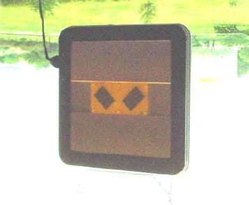
Click to zoom
Application Details
- Equipment Class
- AMP - Amplifier
- Date of Grant
- Jun 13, 2001
- Application Purpose
- Original Equipment
- Date of Application
- Jun 13, 2001
- Equipment Note
- Repeater
- Frequency Range
- 1850.00000000 - 1910.00000000
- Company
- Andrew Corporation
- Country
- United States
Documents & Files
Document Text
Text extracted from the exhibit documents filed with the FCC. Open a document above to read the original.
Users Manual
INSTALLATION & OPERATION MANUAL FOR THE MODEL PRB-1900-xx “PROPAGATOR” INDOOR PCS BAND REPEATERS Contents: 1.0 Regulatory & Safety Information 1.1 FCC Warning Statement 1.2 Safety Considerations 2.0 Equipment Description 2.1 Physical Configuration 2.2 Electronic Description & Block Diagram 2.3 Operational Environment 3.0 Installation Guide lines 3.1 Location 3.2 Mounting 3.3 Power Supply 4.0 Operation Guide Lines 4.1 Power / Interface Circuit Board 4.2 Stability Appendix A: PCS Frequency Band and Blocks Appendix B: Specifications Appendix C: Gain Adjustment 1.0 Regulatory & Safety Information 1.1 FCC Warning Statement WARNING: This device complies with CFR 47, Part 24 of the FCC rules. Any modification not expressly approved by the manufacturer could invalidate the user's authority to operate the device. 1.2 Safety Information CAUTION: In order to comply with FCC rules for Radio Frequency Exposure, the following must be observed: The PROPAGATOR must be installed such that a minimum separation distance of 1.25” (3 cm.) is maintained between each antenna face (the large white plastic 15” X 15” surfaces on each side of the chassis) and any persons. 2.0 Equipment Description 1.2 Physical Configuration Figure 1 is an illustration of the PCS-1900-xx “Propagator” Repeater (hereafter referred to as the SSR) indicating important features. As shown in the illustration there is a main electronics housing (chassis) that has a square shape with rounded corners. The chassis is attached to a mounting base that incorporates an azimuth rotation feature with detents. The approximate size of the chassis is 15” X 15” X 4”; the corners have a 3” radius. The mounting bracket has a base that is approximately 9” X 3.75” X 0.75” that positions the chassis approximately 3.25” away from its mounting surface. The unit weighs approximately 8.75 pounds without the power supply. A separate, AC wall outlet mounted, DC power source is provided. This unit is approximately 3.75” X 2” X 1.25” in size and weighs approximately 0.8 lbs. A white plastic radome covers each 15” X 15” face of the chassis; these surfaces are electrically active and must be kept free of contaminating materials. Also, take special note that each face of the SSR has a unique electrical function and must properly oriented in operation (see section 2.0). The radome with the Andrew flash indicates which side should be facing the handset (mobile unit). 1.3 Electronic Description & Block Diagram The 1900 series PCS repeaters operate in the 1900 MHz PCS band. They were developed to provide more reliable coverage and/or range extension of PCS systems within sheltered structures. Three models cover all US PCS sub-bands (AD, BE, & FC). Pre-aligned antennas on each side of the repeaters make them easy to install and simple to operate. Designed for indoor environments, they only require a standard US 110VAC outlet for operating power. The design employs high linearity amplifiers that work well with all popular signal formats (TDMA, CDMA, GSM, etc.). Figure 2 is an electronic block diagram of SSR internal and external circuitry. A full band internal antenna on the base station face of the SSR (donor antenna) feeds a highly selective diplexer functions to separate and isolate the uplink (Tx) and downlink (Rx) signal paths. A different internal full band antenna and diplexer on the mobile face of the SSR function in a complementary manner to separate and isolate the uplink (Rx) and downlink (Tx) signal paths. The signal from each diplexer’s Rx filter feeds an amplifier with an AGC loop that limits maximum output power to approximately 4 milliwatts. The amplifier RF outputs feed the complementary TX band pass filter in each diplexer which functions to limit spurious amplifier output signals and further isolate the complementary band’s signal. Both amplifiers include Received Signal Strength Indicator (RSSI) circuitry and over- current protection circuitry. 1.4 Operational Environment The SSR has been designed to operate properly in a temperature and humidity controlled indoor environment. Operation in environments where the ambient temperature is outside the 30 o -105 o F range or the relative humidity is greater than 50% may result in unsatisfactory performance. Exposure to temperatures outside the 10 o -120 o F range or relative humidity greater than 90% may result in permanent damage to the unit. 2.0 Installation Guide Lines 2.1 Location Proper operation of the SSR cannot be achieved if the following installation location guide lines are not followed. The prevention of signal feedback from the transmit antenna on one side of the SSR to the same path’s receive antenna on the opposite side of the SSR is paramount to proper operation of the SSR. Any matter in the surrounding environment of the SSR will produce undesirable feedback signals. Any object with any physical dimension that is greater than 2 inches may cause undesirable signal reflections and/or refractions severe enough to cause unstable operation of the SSR. Metal objects normally cause worse reflections and/or refraction than non-metallic objects. The level of undesired reflected and/or refracted signals is directly proportional to the size of the object and inversely proportional to the distance between the SSR and the reflecting/refracting object. Obviously, a perfect “free space” environment for the SSR is the ideal location, but not practical. However, a major goal of the operating location selection process is to find a place that approximates a “free space” environment as closely as possible. A location that provides a “clear” communication link with a suitable base station when using a typical handset is also required for proper operation of the SSR. Base station signal level at various candidate locations should be measured using the RSSI on a handset or more precise instrumentation. Experience indicates that a location with the highest base station signal level that is free of any object within…
Text truncated - open the document above for the full version.
Cover Letter(s)
REQUEST FOR CONFIDENTIALITY Andrew Corporation requests confidentiality with regard to the following documents in the filing for equipment approval identified by FCC ID. No. KUWPCS1900. (1) Schematic diagrams contained in electronic file identified as: Schematics_0.pdf Schematics_A.pdf BlockDiagram.pdf It is the opinion of Andrew Corporation disclosure of this information would result in significant loss of revenue. This information should be kept confidential for 25 years. Authorized Signature ____________________________ Don Stone, Sr. RF Engineer Company Name: Andrew Corporation 2601 Telecom Parkway Richardson, Texas 75082 Distributed Communications System 2601 Telecom Parkway Richardson, Texas 75082
Operational Description
1.1 Physical Configuration Figure 1 is an illustration of the 18” PCS Side to Side Repeater (SSR) indicating important features; Figure 2 is an illustration of the 12” SSR. As shown in the illustrations both SSRs have a square shape with rounded corners; both units have the same physical thickness (approximately 2”). The 18” unit weighs approximately 14.5 pounds; the 12” unit approximately 8 pounds. The 2” wide edge of both units contain 4 deep grooves separated by fins; this structure is an important electrical feature and must be keep free of extraneous material. Likewise, the central 8” square area on each face is electrically active and must be kept free of contaminating materials. Take special note that each face of the SSR has a unique electrical function and must properly oriented in operation (see section 2.0). The illustrations show the SSR without the radomes normally attached to each face. When attached the radome with the Andrew flash indicates which side should be facing the handset (mobile unit). 1.2 Electronic Description & Block Diagram The 1900 series PCS repeaters operate in the 1900 MHz PCS band. They were developed to provide more reliable coverage and/or range extension of PCS systems within sheltered structures. Specific models for each of the major US PCS sub-bands ( A, B, C, D, E & F) are offered. Pre-aligned antennas on each side of the repeaters make them easy to install and simple to operate. Designed for indoor environments, they only require a standard US 110VAC outlet for operating power. All three popular PCS systems (TDMA, CDMA & GSM) are supported. Figure 3 is an electronic block diagram of SSR internal and external circuitry. Separate antennas provide receive and transmit functions for the complementary uplink and downlink bands. In operation, the appropriate receive antenna feeds its’ signal to a band pass filter that functions to reject undesired signals and isolate the complementary band’s signal. The signal from the band pass filter feeds an amplifier with an AGC loop that limits maximum output power to approximately 100 milliwatts. The amplifier output feeds a second band pass filter functioning to limit spurious amplifier output signals and further isolate the complementary band’s signal. The complementary band’s signal path is identical to that previously described, except in the reverse direction. Both amplifiers include crude RSSI circuitry and over-current protection circuitry. 1.3 Operational Environment The SSR has been designed to operate properly in a temperature and humidity controlled indoor environment. Operation in environments where the ambient temperature is outside the 50 o -85 o F range or the relative humidity is greater than 50% may result in unsatisfactory performance. Exposure to temperatures outside the 10 o -120 o F range or relative humidity greater than 80% may result in permanent damage to the unit.
Parts List/Tune Up Info
ANDREW Corp. 2601 Telecom Parkway Richardson, Texas 75082 Andrew Confidential Information 1 of 28 Propagator Production Testing Rev 2, 4/18/2001 JLA 1.0 Scope This document describes the procedures, equipment and set-ups required to manufacture and test the model PCS1900-XX Propagator repeaters. 2.0 Test Equipment Vector Network Analyzer , 100-10000MHz CDMA Signal Generator, 1850-1990MHz Vector Signal Analyzer, 1850-1990 MHz Automatic Noise Figure Meter & Noise Source, 1850-1990MHz Spectrum Analyzer, 100-10000MHz Current Limiting Power Supply, 8-10 volts @10 amps Oscilloscope, 100 MHz. 1 mv VOM PCS 1900 Rx Band Filter PCS 1900 Tx Band Filter Temperature Cycling Chamber, -50 to +100 degrees centigrade 3.0 Figures Illustrations and Data Sheets 3.1 Amplifier Circuit Board Layout. See Figure 3.1. 3.2 Amplifier Circuit Board Gain Test Set-Ups Configure & Calibrate the VNA to measure gain (S21 and/or S12) and Return Loss (S11 and/or S22) over the 1800 to 2050 MHz range using 801 points and -10 dBm test power level prior to testing. Figure 3.2 a is the set-up for uplink channel measurements and Figure 3.2b is the set-up for downlink channel measurements. 3.3 Amplifier Circuit Board ACPR & AGC Test Set-Ups Configure the CDMA signal generator to produce a simulated IS-95 CDMA signal with 18 active channels and configure the Vector Signal Analyzer (or Spectrum Analyzer) to measure ACPR & integrated channel power prior to testing. Figure 3.3 a is the set-up for uplink channel measurements and Figure 3.3b is the set-up for downlink channel measurements. 3.4 Amplifier Circuit Board Noise Figure Test Set-Ups Configure the Automatic Noise figure Meter to measure noise figure over the frequency range of 1850-1990 MHz. Figure 3.4 a is the set-up for uplink channel measurements and Figure 3.4b is the set-up for downlink channel measurements. ANDREW Corp. 2601 Telecom Parkway Richardson, Texas 75082 Andrew Confidential Information 2 of 28 3.5 Diplexer Tuning & Electronic Assembly Gain & Return Loss Test Set-Ups. See Figure 3.5a, 3.5b & 3.5c. Configure and calibrate the VNA to measure gain (S21 and/or S12) and Return Loss (S11 and/or S22) over the 1800 to 2050 MHz range using 801 points and -10 dBm test power level prior to testing. Figure 3.5a shows the test set-up for diplexer tuning. Figures 3.5 b & 3.5c show the test set-up for Gain & Return Loss measurements. 3.6 Electronic Assembly ACPR & AGC Test Set-Ups Configure the CDMA signal generator to produce a simulated IS-95 CDMA signal with 18 active channels and configure the Vector Signal Analyzer (or Spectrum Analyzer) to measure ACPR & integrated channel power prior to testing. Figure 3.6a is the set-up for uplink channel measurements and Figure 3.6b is the set-up for downlink channel measurements. 3.7 Electronic Assembly Noise Figure Test Set-Ups Configure the Automatic Noise figure Meter to measure noise figure over the frequency range of 1850-1990 MHz. Figure 3.7a is the set-up for uplink channel measurements and Figure 3.7b is the set-up for downlink channel measurements. 3.8 Final Functional Test Set-up See Figure 3.8 3.9 Amplifier Circuit Board Data Sheet See Figure 3.9 3.10 Electronics Assembly and Complete Repeater Data Sheet See Figure 3.10 4.0 Tests and Procedure Descriptions 4.1 Temperature Cycling After all electronic components have been installed on the amplifier circuit board, the assembled board shall be subjected to 10 thermal cycles consisting of a 30 minute dwell at –50 degrees centigrade and +100 degrees centigrade with a 30 minute ramp time between temperature plateaus. The boards shall be in a non-powered state. 4.2 Initial Amplifier Board Testing: This testing sequence occurs after the amplifier circuit boards have completed surface mount assembly and non operational temperature cycling . The purpose of this testing sequence is to confirm that the amplifier circuit board ANDREW Corp. 2601 Telecom Parkway Richardson, Texas 75082 Andrew Confidential Information 3 of 28 is operating within the acceptable performance range and to complete the initial adjustment of the board mounted trimmer pots. Proceed as follows: 4.2.1 Mount Amplifier Circuit Board in Amplifier Test Fixture. Remove jumpers J3 & J5; set R10, R23, R30, R53, R59 & R78 to full CCW; if installed, set R32 & R49 to full CW. 4.2.2 Apply DC power; adjust voltage to 9 volts. Check and confirm that green power good LED D7 is illuminated. Measure and record current supplied to DUT. If red fault LED D6 is illuminated, then disconnect DC power, remove amplifier circuit board and route to the diagnosis and repair center. 4.2.3 When the following procedures call for measuring input return loss of either amplifier channel it will be necessary to set trimmer pots R30 & R53 to full CW and remove the 50 dB attenuator. The trimmer pots and 50 dB attenuator must be returned to their initial positions for gain measurements and subsequent adjustments. 4.2.4 Configure the test set-up per Figure 3.2a for uplink channel measurements or Figure 3.2b for downlink channel measurements. Carefully observe the gain and output return loss of both the uplink and down link amplifier channels over the 1800 to 2050 MHz range. The current settings will produce maximum amplifier gains. The VNA display should show smooth monotonic sweeps for all measured parameters. The minimum acceptable gain is 62 dB and the minimum acceptable return loss is 14 dB; over the 1850-1910 MHz band for the uplink amplifier, and over the 1930- 1990 MHz band for the downlink amplifier. Amplifier Boards that do not meet the minimum performance specifications and/or exhibit discontinuities in the sweep performance data should be removed from the test fixture and routed to the diagnosis and repair center. 4.2.5 Install jumpers J3 & J5; adjust R10 & R78 to set the gain of each amplifier channel to 63 dB over the 1850-1910 MHz range for the uplink amplifier and over the 1930-1990 MHz for the downlink amplifier. If the 63 dB gain cann…
Text truncated - open the document above for the full version.
RF Exposure Info
Prediction of MPE limit at a given distance Equation from page 18 of OET Bulletin 65, Edition 97-01 where:S = power density P = power input to the antenna G = power gain of the antenna in the direction of interest relative to an isotropic radiator R = distance to the center of radiation of the antenna Maximum peak output power(e.I.r.p.):20.00(dBm) Maximum peak output power (e.I.r.p.):100(mW) Antenna gain(typical):0(dBi) Maximum antenna gain:1(numeric) Prediction distance:20(cm) Prediction frequency:1900(MHz) MPE limit for uncontrolled exposure at prediction frequency:1(mW/cm^2) Power density at prediction frequency:0.019894(mW/cm^2) Maximum allowable antenna gain:17.0127(dBi) The peak power output listed above is the maximum eirp. The device is mounted in an office environment, typically in a window. The device is able to be moved by an installer in order to get maximum coverage. A statement in the installation manual warns the installer to mount the device with a minimum separation distance of 20 cm. 2 4R PG S π =
Test Report
NEMKO Test Report No.:1L0129RUS1 Applicant:Andrew Corporation Equipment Under Test: PCS Side-to-Side REPEATER FCC ID: KUWPCS1900 In Accordance With:FCC Part 24, Subpart E Broadband PCS Repeaters Tested By: NEMKO Dallas Inc. 802 N. Kealy Lewisville, Texas 75057-3136 Authorized By: Tom Tidwell, RF Group Manager Date: 5/6/01 Total Number of Pages: 91 NEMKO Dallas FCC PART 24, SUBPART E BROADBAND PCS REPEATERS EQUIPMENT: PCS Side-to-Side Repeater FCC ID:PROJECT NO.: 1L0129RUS1 Page 2 of 91 Table of Contents Section 1. Summary of Test Results.......................................................................3 Section 2. General Equipment Specification...........................................................5 Section 3. RF Power Output...................................................................................8 Section 4. Occupied Bandwidth.............................................................................9 Section 5. Spurious Emissions at Antenna Terminals............................................28 Section 6. Field Strength of Spurious....................................................................37 Section 7. Frequency Stability..............................................................................79 Section 8. Test Equipment List.............................................................................80 ANNEX A - TEST DETAILS...............................................................................81 ANNEX B - TEST DIAGRAMS...........................................................................87 NEMKO Dallas FCC PART 24, SUBPART E BROADBAND PCS REPEATERS EQUIPMENT: PCS Side-to-Side Repeater FCC ID:PROJECT NO.: 1L0129RUS1 Page 3 of 91 Section 1.Summary of Test Results Manufacturer: Andrew Corporation Model No.:PCS Side-to-Side Repeater Serial No.:None General:All measurements are traceable to national standards. These tests were conducted on a sample of the equipment for the purpose of demonstrating compliance with FCC Part 24, Subpart E. New SubmissionProduction Unit Class II Permissive ChangePre-Production Unit THIS TEST REPORT RELATES ONLY TO THE ITEM(S) TESTED. THE FOLLOWING DEVIATIONS FROM, ADDITIONS TO, OR EXCLUSIONS FROM THE TEST SPECIFICATIONS HAVE BEEN MADE. See “ Summary of Test Data”. NVLAP LAB CODE: 100426-0 NEMKO Dallas Inc. authorizes the above named company to reproduce this report provided it is reproduced in its entirety and for use by the company’s employees only. Any use which a third party makes of this report, or any reliance on or decisions to be made based on it, are the responsibility of such third parties. NEMKO Dallas Inc. accepts no responsibility for damages, if any, suffered by any third party as a result of decisions made or actions based on this report. This report applies only to the items tested. NEMKO Dallas FCC PART 24, SUBPART E BROADBAND PCS REPEATERS EQUIPMENT: PCS Side-to-Side Repeater FCC ID:PROJECT NO.: 1L0129RUS1 Page 4 of 91 Summary Of Test Data NAME OF TEST PARA. NO.SPEC.MEAS.RESULT RF Power Output24.232100W+20 dBm eirpComplies Occupied Bandwidth (CDMA)24.238Input/OutputPlotsComplies Occupied Bandwidth (GSM)24.238Input/OutputPlotsComplies Occupied Bandwidth (NADC)24.238Input/OutputPlotsComplies Spurious Emissions at Antenna Terminals 24.238(a)-13 dBm> -13 dBmComplies Field Strength of Spurious Emissions 24.238(a) -13 dBm E.I.R.P. > -13 dBmComplies Frequency Stability24.235N/AN / AN / A Footnotes: (1) Modulation characteristics were not tested since the E.U.T. processes but does not produce a modulated waveform. Measurement uncertainty for each test configuration is expressed to 95% probability. NEMKO Dallas FCC PART 24, SUBPART E BROADBAND PCS REPEATERS EQUIPMENT: PCS Side-to-Side Repeater FCC ID:PROJECT NO.: 1L0129RUS1 Page 5 of 91 Section 2.General Equipment Specification Frequency Bands:Downlink: Block A : 1930 – 1945 MHz Block D : 1945 – 1950 MHz Block B : 1950 – 1965 MHz Block E : 1965 – 1970 MHz Block F : 1970 – 1975 MHz Block C : 1975 – 1990 MHz Frequency Bands:Uplink: Block A : 1850 – 1865 MHz Block B : 1865 – 1870 MHz Block C : 1870 – 1885 MHz Block D : 1885 – 1890 MHz Block E : 1890 – 1895 MHz Block F : 1895 – 1910 MHz CDMAGSMNADC (G7W)(GXW)(DXW) Type of Modulation and Designator: Output Impedance: 50 ohms Max Input: 0dBm RF Output (Rated):Uplink Total:+15 dBm RF Output (Rated):Downlink Total:+15 dBm F1-F1F1-F2N/A Frequency Translation: SoftwareDuplexerFullband Band Selection: NEMKO Dallas FCC PART 24, SUBPART E BROADBAND PCS REPEATERS EQUIPMENT: PCS Side-to-Side Repeater FCC ID:PROJECT NO.: 1L0129RUS1 Page 6 of 91 Modifications Made During Testing There were no modifications made during testing. NEMKO Dallas FCC PART 24, SUBPART E BROADBAND PCS REPEATERS EQUIPMENT: PCS Side-to-Side Repeater FCC ID:PROJECT NO.: 1L0129RUS1 Page 7 of 91 Description of Operation System Diagram Window The EUT is a PCS band signal enhancer. The enhancer is essentially an off-air amplifier. The signal that is repeated is repeated on the same signal on which it was received. The function of the EUT is to fill in weak signal areas within a commercial building. The unit is built so that it can be re-located with minimum effort by an installer. The maximum eirp is 100 mW (+20 dBm). EUT Base TX Mobile NEMKO Dallas FCC PART 24, SUBPART E BROADBAND PCS REPEATERS EQUIPMENT: PCS Side-to-Side Repeater FCC ID:PROJECT NO.: 1L0129RUS1 Page 8 of 91 Section 3.RF Power Output NAME OF TEST: RF Power OutputPARA. NO.: 2.1046 TESTED BY: Chinda PoyTTidwellDATE: 4/25/01 Test Results:Complies. Measurement Data: Modulation Type Per Channel Output Power (dBm) Composite Output Power (dBm) UplinkCDMA11.9 dBm14.9 dBm DownlinkCDMA11.7 dBm14.7 dBm UplinkGSM10.8 dBm13.8 dBm DownlinkGSM10.5 dBm13.5 dBm UplinkNADC13.7 dBm16.7 dBm DownlinkNADC13.4 dBm16.4 dBm Equipment Used: 1036-1477-1082 Measurement Uncertainty: +/- 1.6dB Temperature: 22 °C Relative Humidity: 30% NEMKO Dallas FCC PART 24, SUBPART E BROADBAND PCS REPEATERS EQUIPMENT: PCS Side-…
Text truncated - open the document above for the full version.
Test Setup Photos
FCC ID: KUWPCS1900 Test setup photos
Contact Information
Applicant
Matthew O. Thomas(Manager, Customized Products)
Test Firm
Nemko Dallas, Inc.Michael Cantwell
Technical Specifications
| # | Rule Parts | Frequency Range | Power Output | Emission | Tolerance |
|---|---|---|---|---|---|
| 3 | 24 | 1.85 GHz - 1.91 GHz | 100.00 mW | DXW | Amp |
Other Applications from Andrew Corporation
KUWEOCELL24RMT
Feb 06, 2008EOCell Transceiver System
Equipment Class
DTS - Digital Transmission System
KUW800BDA
Dec 12, 2006Downlink Booster
Equipment Class
TNB - Licensed Non-Broadcast Station Transmitter
KUWMAAIS
Aug 20, 2002Bi-Directional Amplifier
Equipment Class
AMP - Amplifier
KUWINCELLERAU1
Jun 02, 2002Repeater
Equipment Class
AMP - Amplifier
KUWINCELL1900
Mar 25, 2001InCell 1900 Repeater
Equipment Class
AMP - Amplifier