KUWINCELL800InCell-800 cellular band repeater
Andrew Corporation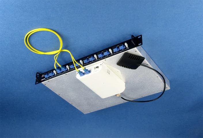
Click to zoom
Application Details
- Equipment Class
- AMP - Amplifier
- Date of Grant
- Jan 04, 2001
- Application Purpose
- Original Equipment
- Date of Application
- Jan 04, 2001
- Equipment Note
- InCell-800 cellular band repeater
- Frequency Range
- 869.00000000 - 894.00000000
- Company
- Andrew Corporation
- Country
- United States
Documents & Files
Document Text
Text extracted from the exhibit documents filed with the FCC. Open a document above to read the original.
Users Manual
I I n n C C e e l l l l ™ ™ F F i i b b e e r r O O p p t t i i c c D D i i s s t t r r i i b b u u t t e e d d A A n n t t e e n n n n a a S S y y s s t t e e m m Installation and Users Guide Copyright Andrew Corporation Version 1.1 October 2000 Andrew InCell™ Fiber Optic Distributed Antenna System Users Guide - ii - Proprietary Information This document is the property of Andrew Corporation. The information contained herein is proprietary to Andrew, and no part of this document may be reproduced or transmitted in any form or by any means, electronic or mechanical, for any purpose, without the express written permission of Andrew. Disclaimer Andrew reserves the right to make changes, without notice, to the specifications and materials contained herein. While we have worked diligently to insure every element presented is correct, we shall not be responsible for errors. For the latest product information and technical specifications, please see the contact information below. Copyright Andrew Corporation, October 2000, Printed in USA, All rights reserved. FCC Notice This equipment complies with Part 22 of the FCC rules. Any changes or modifications not expressly approved by the manufacturer could void the user’s authority to operate the equipment. Warning In order to comply with FCC rules for rf exposure, the following must be observed: 1. The antenna for this device must have a gain of no more than 12.7 dBi. 2. The antenna must be installed such that a minimum separation distance of 20 cm. is maintained between the antenna and any persons. Trademarks InCell™ is a trademark of Andrew Corporation. All other trademarks belong to their respective owner. Contact Information For more information about Andrew’s capabilities to extend RF signals coverage into structures, including office buildings, shopping complexes, warehouses, tunnels, and mines, please contact us using the information below: Andrew Corporation 2601 Telecom Parkway Richardson, Texas 75082 Attention: Mr. Matt Melester E-mail:[email protected] Fax:(972) 952-0018 Voice:(972) 952-9745 Table of Contents Andrew Corporation.................................................................................................................1 Andrew In-Building Wireless Experience................................................................................1 InCell™ Fiber Optic Distributed Antenna System Description..............................................1 Central Distribution Unit (CDU)...........................................................................................1 CDU FRONT PANEL .........................1 Remote Antenna Unit (RAU)................................................................................................2 CDU to RAU Interface Cables..............................................................................................4 Composite Fiber Optic & Power Cables................................................................................4 Standard Duplex Fiber Optic Cables......................................................................................4 Indoor Antennas....................................................................................................................5 In-Building Implementations Using the Andrew InCell™ System.........................................7 Scalable System Architecture................................................................................................7 The Signal Distribution Unit............................................................................................8 The Interconnecting Cable...................................................................................................11 The Installation Parameters...........................................................................................13 Sample Implementation.......................................................................................................16 InCell™ Specifications............................................................................................................17 Technical Performance........................................................................................................17 Interface Specifications.......................................................................................................18 Electrical Specifications......................................................................................................19 Environmental and Mechanical Specifications.....................................................................20 MTBF...........................................................................................................................20 MTTR...........................................................................................................................20 Andrew InCell™ Fiber Optic Distributed Antenna System Users Guide - ii - InCell™ Network Monitoring System...................................................................................21 Pilot Tone Generation.........................................................................................................21 RAU Indicators...................................................................................................................21 CDU Front Panel Indicators................................................................................................21 Alarm Functions..................................................................................................................22 Remote Monitoring Functions.............................................................................................22 InCell™ Operation, Maintenance and Support....................................................................24 Operation............................................................................................................................24 Regular Maintenance............................…
Text truncated - open the document above for the full version.
Cover Letter(s)
REQUEST FOR CONFIDENTIALITY Andrew Corporation requests confidentiality with regard to the following documents in the filing for equipment approval identified by FCC ID. No. KUWINCELL800. (1) Schematic diagrams contained in electronic file identified as: Sch-Amps_RAU.pdf Sch-Amps_CDU.pdf Sch-Amps_PDU.pdf Sch-Amps_CDU_Top Level.pdf Block-Amps_CDU.pdf Block-Amps_PDU.pdf Block-Amps_rau.pdf Block-Amps_System.pdf It is the opinion of Andrew Corporation disclosure of this information would result in significant loss of revenue. This information should be kept confidential for 25 years. Authorized Signature ____________________________ Don Stone, Sr. RF Engineer Company Name:Andrew Corporation 2601 Telecom Parkway Richardson, Texas 75082 Distributed Communications System 2601 Telecom Parkway Richardson, Texas 75082
Cover Letter(s)
Dear Barry, Following are my responses to the issues raised. Regards, Tom ---------------------------------------------------------------------------- Dear Tom, We have conducted our review of the application. The following issues need to be resolved before we can proceed: 1. The spurious radiated data is taken utilizing a procedure similar to ANSI C63.4. This will not be acceptable in the future and may not be acceptable now. The FCC has stated that it is branch policy to require the measurements be made in accordance with ANSI/TIA/EIA-603-1992 Section 2.2.12 substitution method. We believe that the FCC has expressed some clemency and will accept a few more applications with test data taken in this mode, but they could decide not to accept non-substitution data at any time. In light of these developments, you may wish to submit substitution based measurements for this device. Response: This is an issue that we dealt with back in 1990 in correspondence with the Commission. Since there was no test procedure specified at the time, we proposed that field strength measurements be made and the erp derived mathematically using Maxwell's equations. At that time they agreed to the proposal. We have no objection, however, to using the EIA method on future filings. 2. We do not see data for a three signal test in this application. We note that there is mention of a mode in which the device puts up four channels. We do see two signal tests for the various operating modes, but the FCC tells us that they want to see these performed at the band edge (both high and low). If you can't do three signal tests due to equipment limitations it is acceptable to perform the two signal intermod test at the upper and lower band edges. Please submit plots responsive to this request. Response: The two-signal intermodulation tests were performed at lower, middle, and upper band and appear in the report on pages 30 - 35. Attached here is a plot of the intermodulation spurious with three analogue(voice) modulated signals. <<analog intermod.xls>> 3. Please submit a plot of the input vs. the output modulated waveform for each modulation type. Response: The input plots precede the output plots in the report. 4. Please report the DC voltages and currents in the final amplifier stage. Response: Power amplifier is a Stanford Microdevices SXA-289. It uses +5Vdc@ 115 mA. 5. Please submit the amplifier tune-up procedure. This may be a factory procedure used to set the unit's output power. Response: There is no tune-up procedure. The power output is limited by the rf cascade. 6. Please submit a document responsive to the 22.933 requirement for compatibility with OET 53. A statement will be acceptable. Response: The Commission has generally not required this attestation statement for amplifier products since the attestation is intended to address the operability of mobiles and base stations in the AMPS system and an amplifier product really has no impact on this. 7. Please supply a complete users manual so we can check for the necessary statements regarding modifications, compliance and RF exposure. Response: The manual is still in draft form but does include the necessary statements. <<InCell new manual.zip>>
ID Label/Location Info
FCC label location FCC label location
Operational Description
Circuit Description Central Distribution Unit (CDU) The CDU is connected to a Repeater, BDA, or BTS via coaxial cable. The Downlink (Base-to- Mobile) transmit path is distributed to Remote Antenna Units (RAU). PDU card - The rf input signal is distributed to individual CDU cards (up to six per unit) via the Power Distribution (PDU) Board, which consists of simple passive power dividers. Also located on the PDU card is a pilot oscillator that simply generates a pilot tone that is filtered in the Remote Antenna Unit (RAU) and used to verify the rf link. This pilot tone is never transmitted wirelessly. CDU card - In the Downlink direction the CDU card consists of a SAW filter and rf to laser conversion module. Once the rf signal has been converted to light, it is distributed to a Remote Antenna Unit (RAU) via fiber cable. In the Uplink direction, the CDU card simply performs the opposite function. The optic signal fed from the RAU uplink output is converted to rf, amplified, filtered, and finally passed to the PDU card where it will be sent to the external repeater, BDA, or BTS equipment via coaxial cable. Remote Antenna Unit (RAU) In the Downlink direction, the RAU receives the optic signal from the CDU and converts it to rf. At this stage a Low Pass filter sends the pilot tone to a Pilot Detection Circuit, The intended transmit signal is sent through a two-stage amplifier/filter circuit. The resulting signal is fed through a passive duplexer and finally sent to an external antenna via coaxial cable. The external antenna gain is typically 12 dB maximum. In the Uplink direction, the RAU receives an rf signal from the mobile via the external antenna. The rf signal is processed through a filter/gain control circuit through to a rf-to-optic conversion circuit. The optic signal is the sent to the CDU via fiber optic cable.
RF Exposure Info
MPE Prediction for Andrew INCELL800 Repeater Maximum peak power output at antenna input terminal: +22 dBm (158.5 mW) Maximum antenna gain: 7 dBi (5 numeric) Prediction distance: 20 cm MPE limit for uncontrolled exposure at tx frequency of 869 MHz: 869/1500 = .579 mW/cm 2 Using the equation from page 18 of OET Bulletin 65, Edition 97-01to predict the worst-case exposure at 20 cm: 2 4R PG S π = where:S = power density P = power input to the antenna G = power gain of the antenna in the direction of interest relative to an isotropic radiator R = distance to the center of radiation of the antenna 2 /157. 4006.12 55.158 cmmWS= × × = The normal worst-case arrangement of the antenna would be mounted in a ceiling tile. This would guarantee that the antenna would never be closer than 20 cm to any person. To actually exceed the limit of .579 mW/cm 2 , the antenna unit would need to be closer than 10.4 cm. to any person. The maximum allowable gain with a 20 cm. separation would be: )(4.18 5.158 )4006.12(579. 5.158 )4( 2 numeric RS G= ×× = × = π 10log(18.4) = 12.7 dBi Given the above information, the manufacturer recommends a minimum separation distance of 20 cm. and maximum antenna gain of 12.7 dBi.
Test Report
KTL Test Report:0L0296RUS1 Applicant:Andrew Corporation 2601 Telecom Parkway Richardson, Texas 75082-3521 Equipment Under Test:InCell Fiber Optic Distributed Antenna System Model: InCell-800 FCC ID:KUWINCELL800 In Accordance With:FCC Part 22, Subpart H Cellular Band Repeaters Tested By:KTL Dallas Inc. 802 N. Kealy Lewisville, TX 75057-3136 Authorized By: Dale Reynolds, EMC Group Manager Date:12/6/00 Total Number of Pages:56 KTL Dallas FCC PART 22, SUBPART H CELLULAR BAND REPEATERS EQUIPMENT:InCell-800 Fiber Optic Distributed Antenna System FCC ID: KUWINCELL800 PROJECT NO.:0L0296RUS1 Page 2 of 56 Table of Contents SECTION 1. SUMMARY OF TEST RESULTS......................................................................................3 SECTION 2. GENERAL EQUIPMENT SPECIFICATION.......................................................................5 SECTION 3. RF POWER OUTPUT.......................................................................................................7 SECTION 4. OCCUPIED BANDWIDTH.................................................................................................8 SECTION 5. SPURIOUS EMISSIONS AT ANTENNA TERMINALS....................................................17 SECTION 6. FIELD STRENGTH OF SPURIOUS................................................................................36 SECTION 7. FREQUENCY STABILITY...............................................................................................39 SECTION 8. TEST EQUIPMENT LIST................................................................................................40 ANNEX A - TEST DETAILS..............................................................................................................41 ANNEX B - TEST DIAGRAMS..........................................................................................................50 KTL Dallas FCC PART 22, SUBPART H CELLULAR BAND REPEATERS EQUIPMENT:InCell-800 Fiber Optic Distributed Antenna System FCC ID: KUWINCELL800 PROJECT NO.:0L0296RUS1 Page 3 of 56 Section 1.Summary of Test Results Manufacturer:Andrew Corporation Model No.:InCell-800 Serial No.:CDU S/N. P001, RAU S/N. P001 General:All measurements are traceable to national standards. These tests were conducted on a sample of the equipment for the purpose of demonstrating compliance with FCC Part 22, Subpart H. New SubmissionProduction Unit Class II Permissive ChangePre-Production Unit THIS TEST REPORT RELATES ONLY TO THE ITEM(S) TESTED. THE FOLLOWING DEVIATIONS FROM, ADDITIONS TO, OR EXCLUSIONS FROM THE TEST SPECIFICATIONS HAVE BEEN MADE. See “ Summary of Test Data”. NVLAP LAB CODE: 100426-0 KTL Dallas Inc. authorizes the above named company to reproduce this report provided it is reproduced in its entirety and for use by the company’s employees only. Any use which a third party makes of this report, or any reliance on or decisions to be made based on it, are the responsibility of such third parties. KTL Dallas Inc. accepts no responsibility for damages, if any, suffered by any third party as a result of decisions made or actions based on this report. This report applies only to the items tested. KTL Dallas FCC PART 22, SUBPART H CELLULAR BAND REPEATERS EQUIPMENT:InCell-800 Fiber Optic Distributed Antenna System FCC ID: KUWINCELL800 PROJECT NO.:0L0296RUS1 Page 4 of 56 Summary Of Test Data NAME OF TEST PARA. NO. SPEC.RESULT RF Power Output22.913(a)500W ERPComplies Occupied Bandwidth (Voice & SAT)22.917(c)MaskComplies Occupies Bandwidth (Wideband Data)22.917(d)MaskComplies Occupied Bandwidth (ST)22.917(d)MaskComplies Occupied Bandwidth (Digital)NoneNoneComplies Spurious Emissions at Antenna Terminals22.917-13 dBmComplies Field Strength of Spurious Emissions22.917-13 dBm E.I.R.P.Complies Frequency Stability22.3551.5 ppmNot Applicable Footnotes: 1. The E.U.T. does not perform frequency conversion. The frequency stability of the transmitted signal is entirely dependant on the frequency stability of the rf input signal. Measurement uncertainty for each test configuration is expressed to 95% probability. . KTL Dallas FCC PART 22, SUBPART H CELLULAR BAND REPEATERS EQUIPMENT:InCell-800 Fiber Optic Distributed Antenna System FCC ID: KUWINCELL800 PROJECT NO.:0L0296RUS1 Page 5 of 56 Section 2.General Equipment Specification Supply Voltage Input(CDU): 120 VAC via power mains Supply Voltage Input(RAU): 24 VDC from CDU Downlink: 869 – 894 MHz Frequency Range Uplink: 824 – 849 MHz (Distributed to the Repeater or BTS via fiber optic and coaxial cable. This is not a wireless link. CDMANADCAMPS (F9W)(DXW)(F8W, F1D) Type of Modulation and Designator: Output Impedance: 50 ohms Max. Input Power (before damage): +20dBm Max. Input Power: +0dBm VoiceNADCCDMA Downlink: 15 dBm, 2 carriers15 dBm, 2 carriers10 dBm, 1 carrier RF Output (Rated): 12 dBm, 4 carriers12 dBm, 4 carriers4 dBm, 2 carriers 9 dBm, 8 carriers9 dBm, 8 carriers Frequency Translation: F1-F1F1-F2N/A Software Duplexer ChangeFullband Coverage Band Selection: KTL Dallas FCC PART 22, SUBPART H CELLULAR BAND REPEATERS EQUIPMENT:InCell-800 Fiber Optic Distributed Antenna System FCC ID: KUWINCELL800 PROJECT NO.:0L0296RUS1 Page 6 of 56 Description of Operation System Diagram r The DUT (Device Under Test) is a distributed antenna system designed to extend rf coverage into buildings and hard to penetrate indoor areas that experience rf coverage problems. This system is made up of two components: 1) CDU (Central Distribution Unit) - This unit is typically located in a wiring closet. Each CDU can interface to six RAU (Remote Antenna Units). The CDU collects and distributes voice and data signals through fiber cable pairs. The CDU connects to the output of a repeater unit. The Uplink direction is a directly wired connection and cannot connect directly to an antenna. The transmit signals from the repeater are converted from rf to optical and distributed via the fiber cables to a RAU. 2) RAU (Remote Antenna Unit) - This unit converts the signal received fr…
Text truncated - open the document above for the full version.
Test Report
Dallas Headquarters: 802 N. Kealy Lewisville, TX 75057 Tel: (972) 436-9600 Fax: (972) 436-2667 KTL Dallas, Inc. Test Plot: Page 1 of1 Job No.:0L0296RDate:12/21/00 Specification:Part 22Temperature(°C):22 Tested By:David LightRelative Humidity(%)50 E.U.T.: Configuration: Serial Number:P001 Location:Lab 1RBW:30 kHz Detector Type:PeakVBW:30 kHz Antenna:#N/ADirectional Coupler:#N/A Pre-Amp:#N/ACable #1:1081 Filter:#N/ACable #2:#N/A Receiver:1036Cable #3:#N/A Attenuator #11472Cable #4:#N/A Attenuator #2:#N/AMixer:1091 Additional equipment used: Measurement Uncertainty: #N/A Notes: Intermodulation Characteristics - Analog Test Equipment Used CDU & RAU TRANSMIT 3 ANALOG SIGNALS IN AMPS BAND analog intermod
Contact Information
Applicant
Matthew O. Thomas(Manager, Customized Products)
Technical Contact
KTL Dallas, Inc.Tom Tidwell
[email protected]972 436 9600
802 N. Kealy · Lewisville, Texas · United States
Non-Technical Contact
KTL Dallas, Inc.Tom Tidwell
[email protected]972 436 9600
Test Firm
Nemko Dallas, Inc.Michael Cantwell
Technical Specifications
| # | Rule Parts | Frequency Range | Power Output | Emission | Tolerance |
|---|---|---|---|---|---|
| 4 | 22.901(d) | 869 MHz - 894 MHz | 31.60 mW | DXW | Amp |
Other Applications from Andrew Corporation
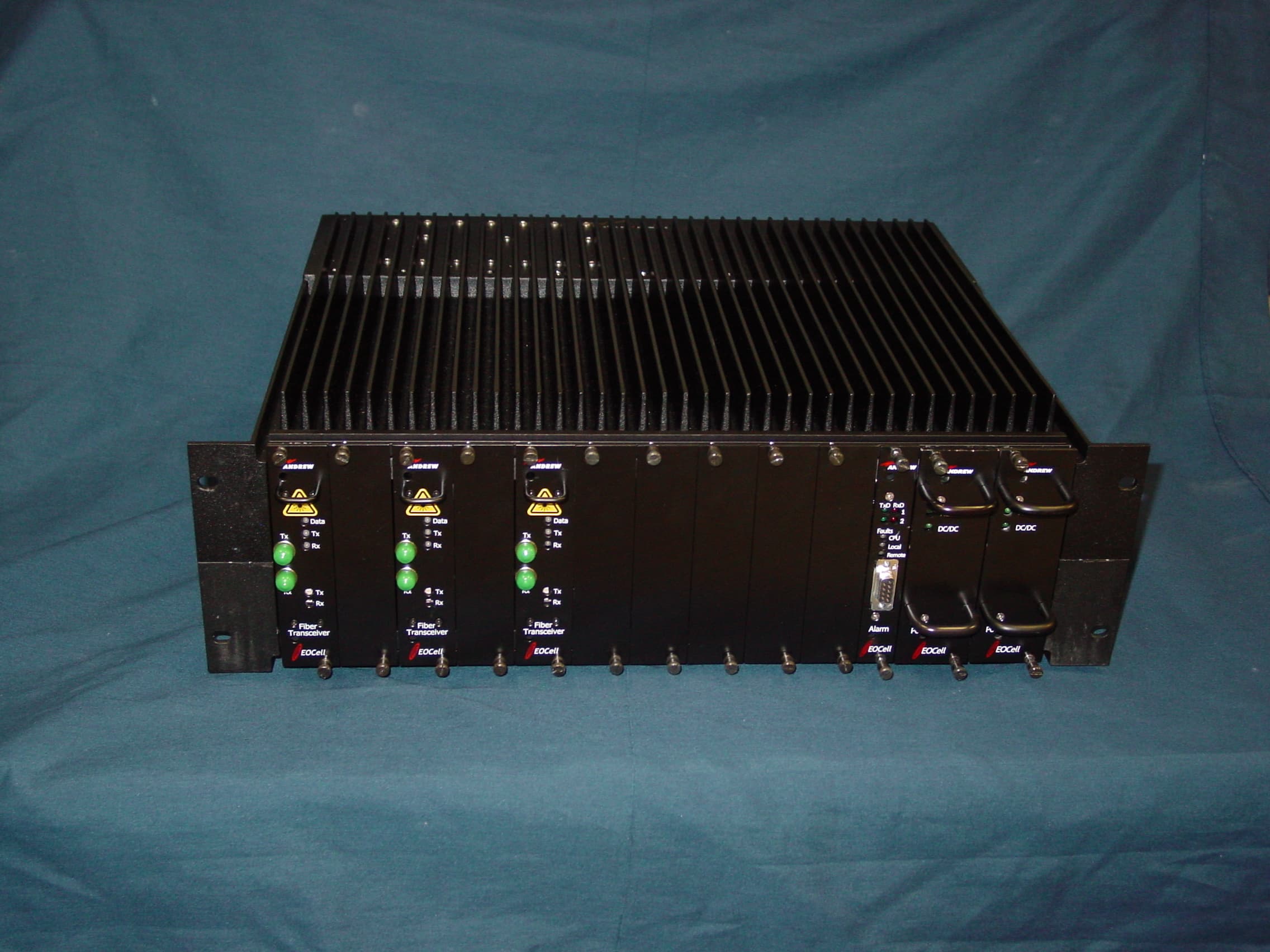
KUWEOCELL24RMT
Feb 06, 2008EOCell Transceiver System
Equipment Class
DTS - Digital Transmission System
KUW800BDA
Dec 12, 2006Downlink Booster
Equipment Class
TNB - Licensed Non-Broadcast Station Transmitter
KUWMAAIS
Aug 20, 2002Bi-Directional Amplifier
Equipment Class
AMP - Amplifier
KUWINCELLERAU1
Jun 02, 2002Repeater
Equipment Class
AMP - Amplifier
KUWPCS1900
Jun 13, 2001Repeater
Equipment Class
AMP - Amplifier