KUWMDL2400BDRBase Station Data Radio
Andrew Corporation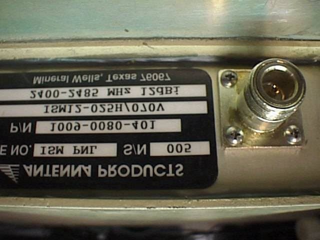
Click to zoom
Application Details
- Equipment Class
- DSS - Part 15 Spread Spectrum Transmitter
- Date of Grant
- Jul 05, 2000
- Application Purpose
- Original Equipment
- Date of Application
- Jan 26, 2000
- Equipment Note
- Base Station Data Radio
- Frequency Range
- 2417.00000000 - 2417.00000000
- Company
- Andrew Corporation
- Country
- United States
Documents & Files
Document Text
Text extracted from the exhibit documents filed with the FCC. Open a document above to read the original.
Users Manual
OPERATION AND MAINTENANCE MANUAL For the MOBILE DATA RADIO AND BASE DATA RADIO MANUAL NO. 385700-1006 REVISION 5 The information set forth in this document and all rights in and to inventions disclosed herein, and patents which might be granted thereon disclosing, employing or covering the materials, methods, techniques or apparatus described herein are the exclusive property of Andrew Corporation. This document is an operation and maintenance manual. No disclosure or reproduction of the information or drawings shall be made of any other purpose without the prior written consent of Andrew. Use of the information contained herein to fabricate or assemble any item in whole or in part is expressly prohibited. 2601 Telecom Parkway, Richardson, Texas 75082-3521 TEL (972) 952-9700 FAX (972) 952-0000 385700-1006-005FCC REQUIREMENTS Document use is restricted to that described on cover A SAFETY SUMMARY High voltage is used in the operation of this equipment. Death on contact may result, if personnel fail to observe the following safety precautions: Do not be misled by the term “Low Voltage.” Potentials as low as 50 Volts may cause death under adverse conditions. Do not crush, puncture, disassemble or otherwise mutilate batteries. Leaking batteries can cause serious damage to equipment and injury to personnel. Do not remove covers or access plates on the equipment, unless you are authorized to do so. Do not work on electronic equipment unless there is another person nearby who is familiar with the operation of the equipment and is trained in administering first aid. Whenever possible, disconnect the equipment from the power source before beginning maintenance. To prevent electrical shock or damage to the equipment, do not operate it until you thoroughly understand the operation and function of all controls, indicators, and connectors. Turn off all power to the equipment before replacing any fuses. FIRST AID In case of electrical shock: Do not try to pull or grab the individual. If possible, turn off the electrical power. If you cannot turn off the electrical power, pull, push, or lift the person to safety using a dry wooden pole, a dry rope, or some other insulating material. Send for help as soon as possible. After the injured person is no longer in contact with the source of electrical shock, move the person a short distance away and immediately administer first aid and artificial resuscitation as required. 385700-1006-005FCC REQUIREMENTS Document use is restricted to that described on cover B This device complies with Part 15 of the FCC rules. Operation is subject to the following two conditions: (1) This device may not cause harmful interference, and (2) This device must accept any interference received, including interference that may cause undesired operation The Base Data Radio and Mobile Data Radios are unlicensed devices operating under the conditions of FCC part 15 regulations. This equipment is intended to be installed and operated by professional parties. It is the responsibility of those parties to insure that the equipment is operated in compliance with the applicable FCC part 15 specifications and the requirements contained in this document. WARNING WARNING 385700-1006-005FCC REQUIREMENTS Document use is restricted to that described on cover C LIST OF ABBREVIATIONS AND ACRONYMS All abbreviations/acronyms used in this manual, other than those listed on this page, are used per MIL-STD-12D. BDRBase Data Radio CDMACode Division Multiple Access EEPROMElectrically Erasable Programmable Read Only Memory ESDSElectrostatic Discharge Sensitive LCPLocal Command Processor LRULine Replaceable Unit MDRMobile Data Radio PCPersonal Computer PNPseudo Noise RBWResolution Bandwidth RCSRadio Communication Subsystem SSRSpread Spectrum Radio TDMATime Division Multiple Access VBWVideo Bandwidth NOTE 385700-1006-005LIST OF REFERENCE DOCUMENTS Document use is restricted to that described on cover D LIST OF REFERENCE DOCUMENTS Interface Control Document Drawings: Assembly, Mobile Data Radio3385700-1000 Cable Assembly: Diagnostic, MDR385700-1805 Power Out, MDR385700-1806 Power In, MDR385700-1807 Data, MDR385700-1808 RCS to Diagnostic, MDR385700-1811 RCS to RS232, MDR385700-1812 RCS to SCP, MDR385700-1813 Assembly, Base Data Radio385700-3000 Cable Assembly: Diagnostic, BDR385700-3805 Power, BDR385700-3806 Data, BDR385700-3808 RCS to Diagnostic. BDR385700-3811 RCS to SCP1, BDR385700-3812 RCS to SCP2, BDR385700-3813 385700-1006-005TABLE OF CONTENTS Document use is restricted to that described on cover i TABLE OF CONTENTS CHAPTER 1............................................................................................................................................1-1 1.1GENERAL MANUAL INFORMATION........................................................................................1-1 1.2PREPARATION FOR STORAGE OR SHIPMENT ....................................................................1-1 1.2.1 Storage..............................................................................................................................1-1 1.2.2 Shipment ...........................................................................................................................1-1 1.3DESCRIPTION OF EQUIPMENT ..............................................................................................1-2 1.3.1 Type of Equipment ............................................................................................................1-2 1.3.2 Purpose of the Equipment.................................................................................................1-2 1.4LOCATIONS AND DESCRIPTIONS OF MAJOR COMPONENTS ...........................................1-2 1.4.1 Mobile Data Radio Assembly ............................................................................................1-4 1.4.2 Base Station Radio Assembly ..................................................................................…
Text truncated - open the document above for the full version.
Users Manual
OPERATION AND MAINTENANCE MANUAL For the MODEL 2400 DISTRIBUTION LINE AMPLIFIER MANUAL NO. 385700-4006 REVISION 6 The information set forth in this document and all rights in and to inventions disclosed herein, and patents which might be granted thereon disclosing, employing or covering the materials, methods, techniques or apparatus described herein are the exclusive property of Andrew Corporation. This document is an operation and maintenance manual. No disclosure or reproduction of the information or drawings shall be made of any other purpose without the prior written consent of Andrew. Use of the information contained herein to fabricate or assemble any item in whole or in part is expressly prohibited . 2601 Telecom Parkway, Richardson, Texas 75082-3521 TEL (972) 952 9700 FAX (972) 952-0000 385700-4006-006SAFETY SUMMARY Document use is restricted to that described on coverA SAFETY SUMMARY High voltage is used in the operation of this equipment. Death on contact may result, if personnel fail to observe the following safety precautions: • Do not be misled by the term “Low Voltage.” Potentials as low as 50 Volts may cause death under adverse conditions. • Do not crush, puncture, disassemble or otherwise mutilate batteries. Leaking batteries can cause serious damage to equipment and injury to personnel. • Do not remove covers or access plates on the equipment, unless you are authorized to do so. • Do not work on electronic equipment unless there is another person nearby who is familiar with the operation of the equipment and is trained in administering first aid. • Whenever possible, disconnect the equipment from the power source before beginning maintenance. • To prevent electrical shock or damage to the equipment, do not operate it until you thoroughly understand the operation and function of all controls, indicators, and connectors. • Turn off all power to the equipment before replacing any fuses. FIRST AID In case of electrical shock: • Do not try to pull or grab the individual. • If possible, turn off the electrical power. • If you cannot turn off the electrical power, pull, push, or lift the person to safety using a dry wooden pole, a dry rope, or some other insulating material. • Send for help as soon as possible. • After the injured person is no longer in contact with the source of electrical shock, move the person a short distance away and immediately administer first aid and artificial resuscitation as required. 385700-4006-006LIST OF ABBREVIATIONS AND ACRONYMS Document use is restricted to that described on coverB The Distribution Line Amplifier is an unlicensed device operating under the conditions of FCC part 15 regulations. This equipment is intended to be installed and operated by professional parties. It is the responsibility of those parties to insure that the equipment is operated in compliance with the applicable FCC part 15 specifications. LIST OF ABBREVIATIONS AND ACRONYMS All abbreviations/acronyms used in this manual, other than those listed on this page, are used per MIL-STD-12D. BDRBase Data Radio USERCommunications-Based Train Control DLADistribution Line Amplifier ESDSElectrostatic Discharge Sensitive FWDForward LRULine Replaceable Unit MDRMobile Data Radio PCPersonal Computer RCSRadio Communication Subsystem RFRadio Frequency RVSReverse SSRSpread Spectrum Radio NOTE WARNING 385700-4006-006LIST OF REFERENCE DOCUMENTS Document use is restricted to that described on coverC LIST OF REFERENCE DOCUMENTS Andrew Catalog 37 (or latest version) Drawings: Assembly, Line Amplifier385700-4000 385700-4006-006TABLE OF CONTENTS Document use is restricted to that described on coveri TABLE OF CONTENTS CHAPTER 1............................................................................................................................................ 1-4 1.1GENERAL MANUAL INFORMATION........................................................................................ 1-4 1.2PREPARATION FOR STORAGE OR SHIPMENT .................................................................... 1-4 1.2.1 Storage.............................................................................................................................. 1-4 1.2.2 Shipment ........................................................................................................................... 1-4 1.3DESCRIPTION OF EQUIPMENT .............................................................................................. 1-5 1.3.1 Type of Equipment ............................................................................................................ 1-5 1.3.2 Purpose of the Equipment................................................................................................. 1-5 1.4LOCATIONS AND DESCRIPTIONS OF MAJOR COMPONENTS ........................................... 1-6 1.4.1 Distribution Line Amplifier Principles of Operation ............................................................ 1-6 1.4.2 Distribution Line Amplifier Major Components .................................................................. 1-9 1.5EQUIPMENT CHARACTERISTICS......................................................................................... 1-10 1.5.1 Power and Utility Requirements ...................................................................................... 1-10 1.5.2 Environmental Information .............................................................................................. 1-10 CHAPTER 2............................................................................................................................................ 2-1 2.1INSTALLING THE DISTRIBUTION LINE AMPLIFIER EQUIPMENT........................................ 2-1 2.1.1 Unpacking and Inspection ................................................................................................. 2-1 2.1.2 Proper Installation of Units ................................................................................................ 2-1…
Text truncated - open the document above for the full version.
Users Manual
OPERATION AND MAINTENANCE MANUAL For the MOBILE DATA RADIO AND BASE DATA RADIO MANUAL NO. 385700-1006 REVISION 6 The information set forth in this document and all rights in and to inventions disclosed herein, and patents which might be granted thereon disclosing, employing or covering the materials, methods, techniques or apparatus described herein are the exclusive property of Andrew Corporation. This document is an operation and maintenance manual. No disclosure or reproduction of the information or drawings shall be made of any other purpose without the prior written consent of Andrew. Use of the information contained herein to fabricate or assemble any item in whole or in part is expressly prohibited . 2601 Telecom Parkway, Richardson, Texas 75082-3521 TEL (972) 952-9700 FAX (972) 952-0000 385700-1006-006FCC REQUIREMENTS Document use is restricted to that described on coverA SAFETY SUMMARY High voltage is used in the operation of this equipment. Death on contact may result, if personnel fail to observe the following safety precautions: • Do not be misled by the term “Low Voltage.” Potentials as low as 50 Volts may cause death under adverse conditions. • Do not crush, puncture, disassemble or otherwise mutilate batteries. Leaking batteries can cause serious damage to equipment and injury to personnel. • Do not remove covers or access plates on the equipment, unless you are authorized to do so. • Do not work on electronic equipment unless there is another person nearby who is familiar with the operation of the equipment and is trained in administering first aid. • Whenever possible, disconnect the equipment from the power source before beginning maintenance. • To prevent electrical shock or damage to the equipment, do not operate it until you thoroughly understand the operation and function of all controls, indicators, and connectors. • Turn off all power to the equipment before replacing any fuses. FIRST AID In case of electrical shock: • Do not try to pull or grab the individual. • If possible, turn off the electrical power. • If you cannot turn off the electrical power, pull, push, or lift the person to safety using a dry wooden pole, a dry rope, or some other insulating material. • Send for help as soon as possible. • After the injured person is no longer in contact with the source of electrical shock, move the person a short distance away and immediately administer first aid and artificial resuscitation as required. 385700-1006-006FCC REQUIREMENTS Document use is restricted to that described on coverB This device complies with Part 15 of the FCC rules. Operation is subject to the following two conditions: (1) This device may not cause harmful interference, and (2) This device must accept any interference received, including interference that may cause undesired operation The Base Data Radio and Mobile Data Radios are unlicensed devices operating under the conditions of FCC part 15 regulations. This equipment is intended to be installed and operated by professional parties. It is the responsibility of those parties to insure that the equipment is operated in compliance with the applicable FCC part 15 specifications and the requirements contained in this document. WARNING WARNING 385700-1006-006FCC REQUIREMENTS Document use is restricted to that described on coverC LIST OF ABBREVIATIONS AND ACRONYMS All abbreviations/acronyms used in this manual, other than those listed on this page, are used per MIL-STD-12D. BDRBase Data Radio CDMACode Division Multiple Access EEPROMElectrically Erasable Programmable Read Only Memory ESDSElectrostatic Discharge Sensitive LCPLocal Command Processor LRULine Replaceable Unit MDRMobile Data Radio PCPersonal Computer PNPseudo Noise RBWResolution Bandwidth RCSRadio Communication Subsystem SSRSpread Spectrum Radio TDMATime Division Multiple Access VBWVideo Bandwidth NOTE 385700-1006-006LIST OF REFERENCE DOCUMENTS Document use is restricted to that described on coverD LIST OF REFERENCE DOCUMENTS Interface Control Document Drawings: Assembly, Mobile Data Radio3385700-1000 Cable Assembly: Diagnostic, MDR385700-1805 Power Out, MDR385700-1806 Power In, MDR385700-1807 Data, MDR385700-1808 RCS to Diagnostic, MDR385700-1811 RCS to RS232, MDR385700-1812 RCS to SCP, MDR385700-1813 Assembly, Base Data Radio385700-3000 Cable Assembly: Diagnostic, BDR385700-3805 Power, BDR385700-3806 Data, BDR385700-3808 RCS to Diagnostic. BDR385700-3811 RCS to SCP1, BDR385700-3812 RCS to SCP2, BDR385700-3813 385700-1006-006TABLE OF CONTENTS Document use is restricted to that described on coveri TABLE OF CONTENTS CHAPTER 1 ............................................................................................................................................ 1-1 1.1GENERAL MANUAL INFORMATION........................................................................................ 1-1 1.2PREPARATION FOR STORAGE OR SHIPMENT .................................................................... 1-1 1.2.1 Storage .............................................................................................................................. 1-1 1.2.2 Shipment ........................................................................................................................... 1-1 1.3DESCRIPTION OF EQUIPMENT .............................................................................................. 1-2 1.3.1 Type of Equipment ............................................................................................................ 1-2 1.3.2 Purpose of the Equipment................................................................................................. 1-2 1.4LOCATIONS AND DESCRIPTIONS OF MAJOR COMPONENTS ........................................... 1-2 1.4.1 Mobile Data Radio Assembly ............................................................................................ 1-4 1.4.2 Base Station Radio Assembly ..............................................................…
Text truncated - open the document above for the full version.
Cover Letter(s)
Andrew Corporation 2601 Telecom Parkway Richardson, Texas U.S.A. 75082-3521 Tel: (972) 952-9700 FAX: (972) 952-0018 6 August 1999 Federal Communications Commission EQUIPMENT AUTHORIZATION BRANCH 7435 Oakland Mills Road Columbia, MD 21046 Re: Agent Authorization To whom it may concern: Andrew Corporation hereby authorizes KTL Dallas, Inc. to act as agent in matters concerning FCC ID: KUWMDL2400BDR. Please contact and/or mail correspondence and original grant to KTL Dallas, Inc. APPLICANT ANTI-DRUG ABUSE CERTIFICATION: In signing this letter, Applicant certifies that, in the case of an individual applicant, he or she is not subject to a denial of federal benefits, that includes FCC benefits, pursuant to Section 5301 of the Anti-Drug Abuse Act of 1988, 21 U.S.C. 853(a), or, in the case of a non-individual applicant (e.g. corporation, partnership or other unincorporated association), no party to the application is subject to a denial of federal benefits, that includes FCC benefits, pursuant to that section. For the definition of a "party" for these purposes, see 47 CFR 1.2002(b). If you have any questions, please contact me at (972) 952-9872. Sincerely, Glenn J. Schedeen Section Leader - DCS Andrew Corporation
Cover Letter(s)
Andrew Corporation 2601 Telecom Parkway Richardson, Texas U.S.A. 75082-3521 Tel: (972) 952-9700 FAX: (972) 952-0018 REQUEST FOR CONFIDENTIALITY Andrew Corporation requests confidentiality with regard to the following documents in the filing for equipment approval identified by FCC ID. No. KUWMDL2400BDR. (1) Schematic diagrams contained in electronic file identified as RF radio schematics.doc. It is the opinion of Andrew Corporation disclosure of this information would result in significant loss of revenue. This information should be kept confidential for 30 years. Glenn J. Schedeen Section Leader Andrew Corporation
ID Label/Location Info
Exhibit A Equipment Label I. Equipment Label Part Number LegendFCC IDUsed On 385700-0040-001KUWMDL2400MDR385700-1000Mobile Data Radio 385700-0040-002KUWMDL2400BDR385700-3000Base Data Radio 385700-0040-002KUWMDL2400BDR385700-4000Distribution Line Amplifier This drawing represents the label that will be placed on the equipment. The labels will be printed on a material which has been selected to last the life of the product. II. Label Location The following drawings represent the labels that will be affixed to the 385700-1000 (Mobile Data Radio – MDR), the 385700-3000 (Base Data Radio – BDR), and the 385700-4000 (Distribution Line Amplifier – DLA). The MDR label will be located on the side of the MDR enclosure. The BDR label will be on the back panel of the BDR enclosure. The DLA label will be located on the side of the DLA enclosure next to the heat sink. Part No. Label FCC Label Figure 1 MDR (385700-1000) FCC Label Location J5J3J4 J5 J4J3J2 Part No. Label FCC Label J1 J1J2 J5 Figure 2 BDR (385700-3000) FCC Label Location Part No. Label FCC Label Figure 3 – DLA (385700-4000) FCC Label Location
Internal Photos
Photo 1 - Base Front Photo 2 - Base Rear Photo 3 - Base Internal Photo 4 - PA Module Bottom Photo 5 - PA Module Top Photo 6 - Baseband and IF card - top Photo 7 - Baseband and IF card bottom Photo 8 - Controller card - top Photo 9 - Controller card bottom Photo 10 - Diplexer module Photo 11 - Diplexer module bottom Photo 12 - Motherboard top with shields Photo 13 - Motherboard without shields Photo 14 - Motherboard bottom Photo 15 - Base PA module Photo 16 - Line Amplifier External View Photo 17 - Line Amplifier External View Side Photo 18 - Line Amplifier Internal View Photo 19 - AC/DC converter module Photo 20 - Line Amplifier LNA Control board Photo 21 - Line Amp LNA module top Photo 22 - Line Amp PA module Photo 23 - Line Amp Control Board Photo 24 - Line Amp PA Photo 25 - Line Amp PA module top Photo 26 - Line Amp PA module bottom
RF Exposure Info
SAR Compliance Statement The transmitter device associated with approval number KUWMDL2400BDR complies with the requirements for Maximum Permissible Exposure based on the following basis: 1. The device will always be installed such that the radiator is more than 20 cm from the general public. A typical installation would be in a subway tunnel. 2. The device is professionally installed. - The manufacturer sells directly to companies that would be qualified to install such equipment. In many cases the manufacturer installs the device themselves. - A statement has been added to the manual instructing the installer to maintain a minimum 20 cm separation from the radiator and the general public. 3. When the device is installed with the leaky coax radiator, the measured radiated field at 3 meters is 65.2 dBuV/m which relates to 1 microwatt E.I.R.P.. The location of the leaky feeder would therefore not be critical as would the installation with a high gain antenna.
Test Report
Master: ktlPT15CDST Date: April 19, 1999 KTL Test Report:9L0023RUS Applicant:Andrew Corporation 2601 Telecom Parkway Richardson, Tx. Equipment Under Test:2400 Base Data Radio (P/N 38700-3000-001) (E.U.T.) FCC ID:KUWMDL2400BDR In Accordance With:FCC Part 15, Subpart C Direct Sequence Transmitters 2.4 – 2.4835 GHz Tested By:KTL Dallas Inc. 802 N Kealy Lewisville, Tx 75057-3136 Authorized By: Tom Tidwell, RF Group Manager Date:January 4, 2000 Total Number of Pages:42 KTL Dallas, Inc.FCC PART 15, SUBPART C DIRECT SEQUENCE TRANSMITTERS PROJECT NO.: 9L0023RUS EQUIPMENT: 2400 Base Data Radio(P/N 385700-3000-001) FCC ID: Page 2 of 42 Table Of Contents Section 1. Summary of Test Results General..............................................................................................04 Summary of Test Data....................................................................................05 Section 2. General Equipment Specification Specifications - Transmitter............................................................................06 Specifications - Receiver...........................................................................07 Modifications...............................................................................................08 Family List Rational.....................................................................................08 Theory of Operation.....................................................................................09 System Diagram.....................................................................................09 Section 3. Powerline Conducted Emissions Test Results...............................................................................................10 Graphs.....................................................................................................11-13 Section 4. Occupied Bandwidth Test Results...............................................................................................14 Graphs...............................................................................................15 Section 5. Peak Power Output Test Results...............................................................................................16 Peak Power Output Table...........................................................................18 Section 6. Spurious Emissions (Antenna Conducted) Test Results...............................................................................................19 Graphs..................................................................................20- 22 Section 7. Spurious Emissions (Radiated) Test Results...............................................................................................23 Test Data - Radiated Emissions (PEAK) ................................24-25 Test Data - Radiated Emissions (AVERAGE)........................................................25 Radiated Photographs.....................................................................................26 Section 8. Transmitter Power Density Test Results...............................................................................................27 Graphs...............................................................................................28 KTL Dallas, Inc.FCC PART 15, SUBPART C DIRECT SEQUENCE TRANSMITTERS PROJECT NO.: 9L0023RUS EQUIPMENT: 2400 Base Data Radio(P/N 385700-3000-001) FCC ID: Page 3 of 42 Table Of Contents, continued Section 9. Processing Gain Test Results.....................................................................................29 Processing Gain Data...........................................................................30 Additional Data.....................................................................................31 Section 10. Test Equipment List Test Equipment List..............................................................................32 Annex A. Test Methodologies Powerline Conducted Emissions........................................................A2 Occupied Bandwidth.................................................................A3 Peak Power Output.................................................................A4 Spurious Emissions at Antenna Terminal.......................................................A6 Radiated Spurious Emissions.................................................................A7 Transmitter Power Density.................................................................A8 Processing Gain.................................................................A9 Annex B. Block Diagrams Test Site for Radiated Emissions.................................................................B2 Conducted Emissions.................................................................B2 Transmitter Power Density & Peak Power at Antenna Terminals..........................B3 Processing Gain.................................................................B3 KTL Dallas, Inc.FCC PART 15, SUBPART C DIRECT SEQUENCE TRANSMITTERS PROJECT NO.: 9L0023RUS EQUIPMENT: 2400 Base Data Radio(P/N 385700-3000-001) FCC ID: Page 4 of 42 Section 1.Summary Of Test Results Manufacturer:Andrew Corporation Model No.:2400 Base Data Radio Serial No.:BDR052 General:All measurements are traceable to national standards. These tests were conducted on a sample of the equipment for the purpose of demonstrating compliance with FCC Part 15, Subpart C, Paragraph 15.247 for Direct Sequence Spread Spectrum devices. New SubmissionProduction Unit Class II Permissive ChangePre-Production Unit THIS TEST REPORT RELATES ONLY TO THE ITEM(S) TESTED. THE FOLLOWING DEVIATIONS FROM, ADDITIONS TO, OR EXCLUSIONS FROM THE TEST SPECIFICATIONS HAVE BEEN MADE. See “ Summary of Test Data”. NVLAP LAB CODE: 100426-0 Ron Gaytan8/10/99-8/17/99TESTED BY:DATE: KTL Dallas Inc. authorizes the above named company to reproduce this report provided it is reproduced in its entirety and for use by the company’s employees only. Any use which a thi…
Text truncated - open the document above for the full version.
Test Report
KTL Test Report:9L0023RUS Applicant:Andrew Corporation 2601 Telecom Parkway Richardson, Tx. Equipment Under Test:2400 Base Data Radio (P/N 38700-3000-001) and 4 Port Line Amplifier FCC ID:KUWMDL2400BDR In Accordance With:FCC Part 15, Subpart C Direct Sequence Transmitters 2.4 – 2.4835 GHz Tested By:KTL Dallas Inc. 802 N Kealy Lewisville, Tx 75057-3136 Authorized By: Tom Tidwell, RF Group Manager Date:January 4, 2000 Total Number of Pages:50 KTL Dallas, Inc.FCC PART 15, SUBPART C DIRECT SEQUENCE TRANSMITTERS PROJECT NO.: 9L0023RUS EQUIPMENT: 2400 Base Data Radio(P/N 385700-3000-001) and 4-Port Line Amplifier FCC ID: KUWMDL2400BDR Page 2 of 50 Table Of Contents Section 1. Summary Of Test Results........................................................................................3 Section 2. General Equipment Specification.............................................................................5 Section 3. Powerline Conducted Emissions..............................................................................11 Section 4. Occupied Bandwidth...............................................................................................18 Section 5. Peak Power Output.....................................…
Text truncated - open the document above for the full version.
Contact Information
Applicant
Matthew O. Thomas(Manager, Customized Products)
Technical Contact
KTL Dallas, Inc.Tom Tidwell
[email protected]972-436-9600
802 N. Kelay · Lewisville, Texas · United States
Non-Technical Contact
KTL Dallas, Inc.Tom Tidwell
[email protected]972-436-9600
Test Firm
KTL Dallas, Inc.Pat Wellborn
Technical Specifications
| # | Rule Parts | Frequency Range | Power Output |
|---|---|---|---|
| 1 | 15C | 2.42 GHz - 2.42 GHz | 1 W |
Other Applications from Andrew Corporation
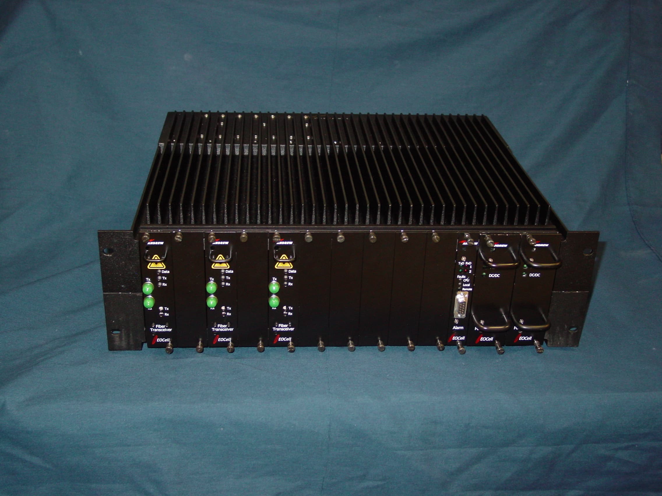
KUWEOCELL24RMT
Feb 06, 2008EOCell Transceiver System
Equipment Class
DTS - Digital Transmission System
KUW800BDA
Dec 12, 2006Downlink Booster
Equipment Class
TNB - Licensed Non-Broadcast Station Transmitter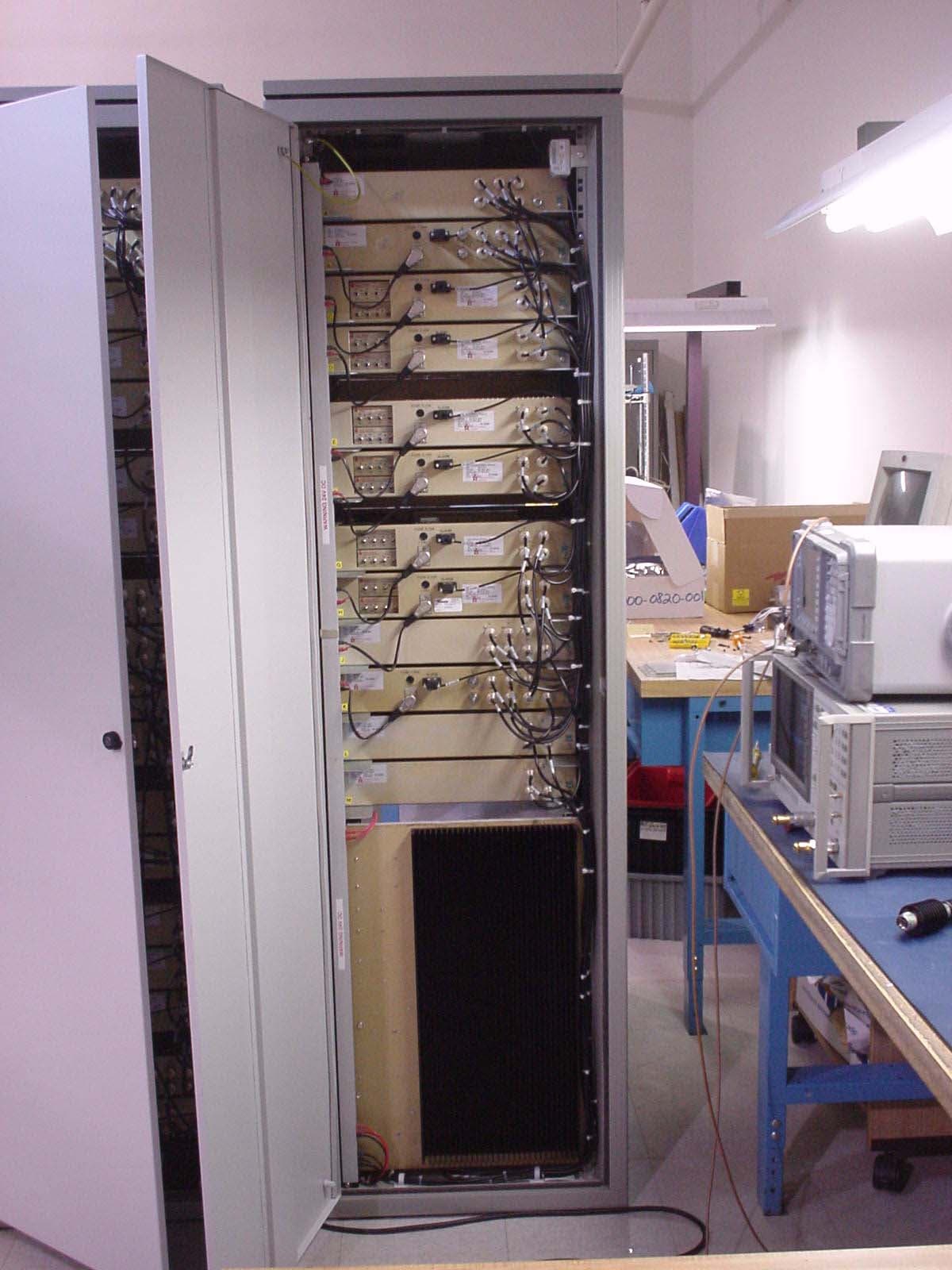
KUWMAAIS
Aug 20, 2002Bi-Directional Amplifier
Equipment Class
AMP - Amplifier
KUWINCELLERAU1
Jun 02, 2002Repeater
Equipment Class
AMP - Amplifier
KUWPCS1900
Jun 13, 2001Repeater
Equipment Class
AMP - Amplifier