KUWNBPCS-9002WChannelized Paging Repeater
Andrew Corporation
Click to zoom
Application Details
- Equipment Class
- TNB - Licensed Non-Broadcast Station Transmitter
- Date of Grant
- Sep 27, 1999
- Application Purpose
- Original Equipment
- Date of Application
- Jul 15, 1999
- Equipment Note
- Channelized Paging Repeater
- Frequency Range
- 940.00000000 - 941.00000000
- Company
- Andrew Corporation
- Country
- United States
Documents & Files
Document Text
Text extracted from the exhibit documents filed with the FCC. Open a document above to read the original.
Users Manual
11 June 2001 USER’S GUIDE for the SELECTAMP NBPCS-900-3 CHANNELIZED PAGING REPEATER MANUAL NO. AE02B-A3659 REVISION -- The information set forth in this document and all rights in and to inventions disclosed herein, and patents which might be granted thereon disclosing, employing or covering the materials, methods, techniques or apparatus described herein are the exclusive property of Andrew Corporation. This document is an operation and maintenance manual. No disclosure or reproduction of the information or drawings shall be made of any other purpose without the prior written consent of Andrew. Use of the information contained herein to fabricate or assemble any item in whole or in part is expressly prohibited. These goods are subject to U.S. Department of State, International Traffic in Arms Regulations, 22 CFR 120-130. 2601 Telecom Pkwy, Richardson, Texas 75082 TEL (972) 952-9700 FAX (972) 952-0019 AE02B-A3659 Rev. --LIST OF EFFECTIVE PAGES Document use is restricted to that described on coveri LIST OF EFFECTIVE PAGES Dates of issue for original and changed pages are: Original....................O ................... 9 June 1999 TOTAL NUMBER OF PAGES IN THIS PUBLICATION IS 18 CONSISTING OF THE FOLLOWING: PageChange No. (O = Original Page) Title PageO List of Effective Pages (i)O Safety Summary (ii)O Table of Contents (iii)O Chapter 1 (1-1 thru 1-3)O Chapter 2 (2-1)O Chapter 3 (3-1 thru 3-5)O Chapter 4 (4-1)O Appendix A (A-1)O Appendix B (B-1 thru B-3)O AE02B-A3659 Rev. --SAFETY SUMMARY Document use is restricted to that described on coverii SAFETY SUMMARY High voltage is used in the operation of this equipment. Death on contact may result if personnel fail to observe the following safety precautions: ·Do not be misled by the term "Low Voltage." Potentials as low as 50 volts may cause death under adverse conditions. ·Do not crush, puncture, disassemble, or otherwise mutilate batteries. Leaking batteries can cause serious damage to equipment and injury to personnel. ·Do not remove covers or access plates on the equipment unless you are authorized to do so. ·Do not work on electronic equipment unless there is another person nearby who is familiar with the operation of the equipment and is trained in administering first aid. ·Whenever possible, disconnect the equipment from the power source before beginning maintenance. ·To prevent electrical shock or damage to the equipment, do not operate it until you thoroughly understand the operation and function of all controls, indicators, and connectors. ·Turn off all power to the equipment before replacing any fuses. FIRST AID In case of electrical shock: ·Do not try to pull or grab the individual. ·If possible, turn off the electrical power. ·If you cannot turn off the electrical power, pull, push, or lift the person to safety using a dry wooden pole, a dry rope, or some other insulating material. ·Send for help as soon as possible. ·After the injured person is no longer in contact with the source of electrical shock, move the person a short distance away and immediately administer first aid and artificial resuscitation as required. AE02B-A3659 Rev. --TABLE OF CONTENTS Document use is restricted to that described on coveriii TABLE OF CONTENTS CHAPTER 1 DESCRIPTION .................................................................................................................. 1-1 1.1OVERVIEW .................................................................................................................................. 1-1 1.2ELECTRICAL SPECIFICATIONS................................................................................................ 1-1 1.3MECHANICAL SPECIFICATIONS .............................................................................................. 1-2 1.4ENVIRONMENTAL SPECIFICATIONS ....................................................................................... 1-2 1.5TECHNICAL ASSISTANCE ........................................................................................................1-2 CHAPTER 2 OPERATIONAL OVERVIEW ............................................................................................ 2-1 2.1OVERVIEW .................................................................................................................................. 2-1 2.2RF DISTRIBUTION ...................................................................................................................... 2-1 2.3POWER DISTRIBUTION ............................................................................................................. 2-1 2.4CONTROL/ DISTRIBUTION ........................................................................................................2-1 CHAPTER 3 FUNCTIONAL DESCRIPTION.......................................................................................... 3-1 3.1OVERVIEW .................................................................................................................................. 3-1 3.2FUNCTIONAL DESCRIPTION .................................................................................................... 3-1 3.2.1 Diplexer ............................................................................................................................ 3-1 3.2.2 Broadband Module ...........................................................................................................3-1 3.2.2.1 LNA/Splitter ......................................................................................................... 3-1 3.2.2.2 Combiner ............................................................................................................. 3-1 3.2.3.3 901 MHz Reverse Channel ................................................................................. 3-2 3.2.3 Channelizer ...................................................................................................................... 3-2 3.2.3.1 Downconverter ...........................................…
Text truncated - open the document above for the full version.
Users Manual
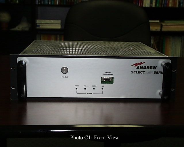
AE02B-A3659 Rev --DESCRIPTION Document use is restricted to that described on cover1-1 CHAPTER 1 DESCRIPTION 1.1OVERVIEW The SelectAmp NBPCS-900-3 bi-directional channelized paging repeater provides selective frequency amplification of user specified frequencies in the 901-902, 930-931, and 940-941 MHz Narrowband PCS bands. The unit can be configured with up to three channelizers allowing the user to configure the unit to suit their needs. The channelizers are available in two versions: a 930 MHz, 12.5 kHz Bandwidth version intended for POCSAG/FLEX and a 940 MHz, 50 kHz Bandwidth version intended for ReFLEX. Frequency selection, gain adjustment and fault monitoring is accomplished with monitor and control circuitry and firmware. Within this manual, “Forward Channel” refers to the RF signal path from the base station to the pager and the “Reverse Channel” refers to the RF signal path from the pager to the base station. 1.2ELECTRICAL SPECIFICATIONS Table 1-1 below contains the electrical specifications. Table 1-1 Electrical Specifications ParametersSpecification Frequency RangeForward (930) = 928 – 932 MHz. Forward (940) = 938 – 942 MHz. Reverse = 897 – 903 MHz. Composite Output PowerForward = 1 Watt. Reverse = 500 mWatts. Output 1 dB Compression PointForward = 4 Watts. Reverse = 1.3 Watts. Power Gain Fwd Channels Rev Channel 50 to 95 dB nominal, adjustable from front panel. 50 to 85 dB nominal, adjustable from front panel. Third Order Output IP3Forward = +51 dBm. Reverse = +43 dBm. AE02B-A3659 Rev --DESCRIPTION Document use is restricted to that described on cover1-2 1.2ELECTRICAL SPECIFICATIONS (CONT.) Table 1-1 (Cont.) Electrical Specifications ParametersSpecification Forward 1 dB Bandwidth: 930 MHz, POCSAG/FLEX Channelizer 940 MHz, ReFLEX Channelizer Reverse 3 dB Bandwidth 12.5 kHz. 50 kHz. 897 – 903 MHz. Group Delay Forward = ≤ 30μs Reverse = ≤ 2μs Adjacent Channel Rejection: 930 MHz, POCSAG/FLEX Channelizer 940 MHz, ReFLEX Channelizer ≥ 30 dB @ F o ± 12.5 kHz. ≥ 30 dB @ F o ± 55 kHz. RF Port Impedance50 ohms nominal. Maximum Input Signal Without damage-30 dBm with gain set for minimum on all channels. AC Input Power100 to 240 VAC, 50/60 Hz, 3A ¼” x 1¼” 240V 3A SLO-BLOW FUSE StatusFront panel indicators. Remote Fault Monitoring Contact Closure: Normal = contacts closed (approx 23 Ω). Fault = contacts open. AE02B-A3659 Rev --DESCRIPTION Document use is restricted to that described on cover1-3 1.3MECHANICAL SPECIFICATIONS Table 1-2 below contains the mechanical specifications. Table 1-2 Mechanical Specifications ParametersSpecification SizeAmplifier: Height:13.3 cm (5.25 inches). Width:48.3 cm (19 inches). Depth:48.3 cm (19 inches). WeightAmplifier:40 lbs (18.2 kg). MountingTable top mount (rubber feet included) or 19” Rack Mount (slides optional). Power ConnectionsAC Power cord supplied with unit. RF ConnectionsType N female. Remote Fault ConnectionType RJ-11, Pins 2,3. 1.4ENVIRONMENTAL SPECIFICATIONS Table 1-3 below contains the environmental specifications for the Band Selective Amplifier. Table 1-3 Environmental Specifications ParametersSpecification Temperature Range (Operating) Operating:0° to +50°C Storage:-20° to +70°C. Humidity Range (Operating)10% to 90% non-condensing. Environmental ProtectionNone. 1.5TECHNICAL ASSISTANCE Technical assistance on this or any other Andrew product is available 24 hours per day through: Andrew Customer Service Telephone: 1-800-255-1479 Fax: 1-972-952-0019
Users Manual
AE02B-A3659 Rev --OVERVIEW Document use is restricted to that described on cover2-1 CHAPTER 2 OPERATIONAL OVERVIEW 2.1OVERVIEW The SelectAmp NBPCS-900-3 Paging Repeater accepts inputs in the 928 – 942 MHz paging band, and selectively passes one discrete channel in each band while rejecting the others. This is accomplished by downconverting the desired signals to a 45 MHz intermediate frequency and using narrowband crystal filters to provide adjacent channel rejection. The reverse path is not channelized, passing all frequencies in the 897 – 903 MHz band. 2.2RF DISTRIBUTION The amplifier contains two paths; forward for the base station to pager signal and reverse for the pager to base station signal. The forward path includes a diplexer, low noise amplifier and splitter, channelizer, combiner, and power amplifier. The channelizers determine the frequencies to be amplified and provide the gain control. The reverse path includes a diplexer, broadband module (amplifier and filters), and a power amplifier. 2.3POWER DISTRIBUTION Main power for the amplifier is provided by a 6.7 amp power supply operating at +15 VDC. The power supply accepts 100 - 240 VAC inputs. This +15 VDC output of the power supply is routed to the Control/Distribution board. The Control/Distribution board regulates and outputs the +15 volts, +12 volts, and +5 volts to the various modules. 2.4CONTROL/DISTRIBUTION The operator has control over the gain and operating frequency of the forward paths, and gain only of the reverse path. The gain setting is controlled via front panel accessible pots. The forward channel frequencies are entered through software installed on a PC/Laptop and sent to the Control/Distribution board. The channel setting is then sent via a three wire serial interface from the Control/Distribution to a synthesizer in each channelizer. Each active module in the amplifier outputs status line(s) to indicate the overall condition of the active devices. If an active device fails, the module reports a fault (red indicator) on the front panel. The reference oscillator for the channelizer synthesizers is located on the Control/Distribution board as well.
Users Manual
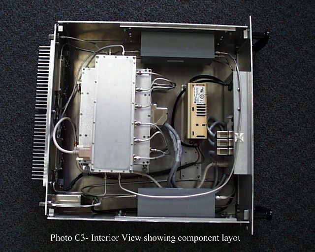
AE02B-A3659 Rev --FUNCTIONAL DESCRIPTION Document use is restricted to that described on cover3-1 CHAPTER 3 FUNCTIONAL DESCRIPTION 3.1OVERVIEW The SelectAmp Channelized Paging Repeater accepts inputs in the 928 – 942 paging band, and selectively passes one discrete channel in each band while rejecting the others. In the forward channels this is accomplished by downconverting the desired signals to a 45 MHz intermediate frequency and using narrowband crystal filters to provide adjacent channel rejection. The reverse path is not channelized, passing all frequencies in the 897 – 903 MHz band. 3.2FUNCTIONAL DESCRIPTION Refer to Figure 3-1. The amplifier contains two paths; forward for the base station to pager signal and reverse for the pager to base station signal. The forward path includes a diplexer, low noise amplifier and splitter, channelizer, combiner, and power amplifier. The channelizers determine the frequencies to be amplified and provide the gain control. The reverse path includes a diplexer, broadband module (amplifier and filters), and a power amplifier. Diplexing of the forward and reverse channels is accomplished by diplexer filters tuned to the appropriate frequencies. 3.2.1DIPLEXER The diplexer module consists of dual filters with a common port on one end and two separate ports on the other. One side of the diplexer is tuned for the forward channel, the other side for the reverse channel. Insertion loss of each filter is 2 dB maximum and 65 dB minimum rejection to the opposite band. 3.2.2BROADBAND MODULE The broadband module contains three boards, each mounted in its own compartment. The forward channel signals are routed through the LNA/Splitter and Combiner boards. The reverse channel signal is routed through the 901 MHz board. Each board is described in more detail below. 3.2.2.1 LNA/SPLITTER The LNA/Splitter module contains the first active devices in the forward channel path. It consists of a low noise amplifier, 3-way power splitter, and a gain stage and filter per path. The amplifiers bias voltages are monitored for a fault condition and reported to the control/distribution module. 3.2.2.2 COMBINER The Combiner module consists of a 3-way power combiner, a gain stage and filter, and a level detector circuit. AE02B-A3659 Rev --FUNCTIONAL DESCRIPTION Document use is restricted to that described on cover3-2 Figure 3-1. SelectAmp NBPCS-900-3 Outline Drawing, front view. 3.2.2.3 901 MHZ REVERSE CHANNEL The 901 MHz reverse channel module provides four gain stages, filtering, and gain adjustment via the front panel. 3.2.3CHANNELIZER The channelizer module contains three boards, each mounted in their own compartment. These three boards, which are described below, provide the channel selectivity. The channelizer module gain is approximately 40 dB. CHANNELIZERS (A4,A5,A6) DIPLEXER (A8) FRONT PANEL (A13) BROADBAND (A7) FWD CHANNEL PA (A12) REV CHANNEL PA (A10) CONTROL/DISTRIBUTION (A1) DIPLEXER (A9) POWER SUPPLY (A2) AE02B-A3659 Rev --FUNCTIONAL DESCRIPTION Document use is restricted to that described on cover3-3 Figure 3-2. SelectAmp NBPCS-900-3 Outline Drawing, rear view. 3.2.3.1 DOWNCONVERTER The downconverter board consists of a mixer driven by a synthesizer, a crystal filter centered at 45 MHz with either a 12.5 KHz (930 MHz channelizer), a 50 KHz (940 MHz ReFlex50 channelizer), or a 25 KHz (940 MHz ReFlex25 channelizer) 1 dB bandwidth. It has one fixed gain stage, and a variable gain stage to provide overall gain adjustment. A Receive Signal Strength Indicator (RSSI) circuit measures the received signal strength and outputs a dc voltage to the Control/Distribution board. The DC current draw of each gain stage is monitored by a window comparator. The window comparator indicates a fault, if the gain stage has an open or short condition. The output of the down converter is fed to the upconverter board. AE02B-A3659 Rev --FUNCTIONAL DESCRIPTION Document use is restricted to that described on cover3-4 3.2.3.2 UPCONVERTER The upconverter board mixes the filtered 45 MHz IF with a signal from the synthesizer and outputs the same frequency that was input to the downconverter. The upconverter consists of a mixer, gain stage, and filter. The DC current draw of each gain stage is monitored by a window comparator. The window comparator indicates a fault, if the gain stage has an open or short condition. 3.2.3.3 SYNTHESIZER The synthesizer board consists of a synthesizer circuit that is driven by a reference oscillator and distribution amplifiers. The synthesizer operating frequency is programmed from the Control/Distribution module. The forward channel frequencies are set with a computer that has Andrew designed frequency control software installed on it. This software is a Microsoft Windows 95/98/NT application that allows the operator to input the desired channel frequency. The Control/Distribution module converts the operator's input to the appropriate frequency command for the synthesizer. The output of the synthesizer is divided into a downconverter path and an upconverter path. 3.2.4POWER SUPPLY The power supply assembly consists of a Power Entry Module and switching power supply. The power supply accepts a 100 to 240 VAC, 3A, 50/60 Hz input and outputs +15 VDC for use by the rest of the amplifier. Power is distributed to the active modules through the Control/Distribution board. 3.2.5CONTROL/DISTRIBUTION MODULE The control/distribution module distributes power to the other modules, receives and processes status and fault information, and provides forward channel frequency control. Power distribution consists of current monitoring of both the forward and reverse channel PA’s, linearly regulating the +15 VDC down to +12 and +5 VDC for various modules. Status functions include monitoring RSSI voltages from the channelizers, monitoring forward output power, and driving the appropriate front panel LED’s. Channel frequency selection information is received via RS-232 from the front pan…
Text truncated - open the document above for the full version.
Users Manual
AE02B-A3659 Rev --MAINTENANCE Document use is restricted to that described on cover 4-1 CHAPTER 4 MAINTENANCE 4.1MAINTENANCE PROCEDURES The SelectAmp contains no user-serviceable parts. To verify operation check the amplifier against the electrical specifications provided in Chapter 1. If the amplifier does not meet these specifications, return the defective unit to the address below for repair: RF Amplifier Group Andrew Corporation 2601 Telecom Pkwy Richardson, Texas 75082 Telephone 972-952-9700 Fax 972-952-0019 To ensure the rapid repair and return of defective items, certain information must accompany any return. Please call the Andrew Technical Support Hot Line and request the Customer Return Instructions. The hot line is available, 24 hours a day, 7 days a week, by calling 1-800-255-1479.
Users Manual
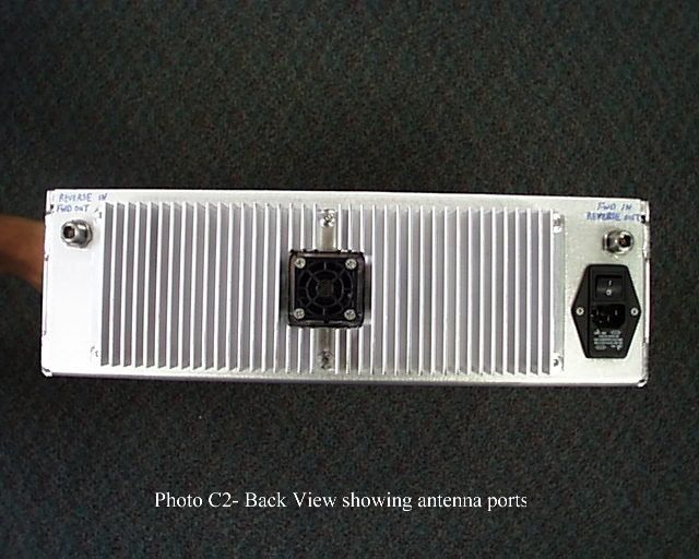
AE02B-A3659 Rev --APPENDIX A Document use is restricted to that described on coverA-1 APPENDIX A EQUIPMENT LIST AND INSTALLATION 1.List of Material •Qty 1 - SelectAmp NBPCS-900-3 Paging Repeater •Qty 1 - User’s Guide (AE02B-A3659) •Qty 1 - Programming Cable (ECABA-20058) •Qty 1 - Adapter, DB-9 (M) to DB-25 (F) (ECNND-95003) •Qty 1 - Power Cable, 6 ft. (ECABL-31111) •Qty 1 - Diskettes (3) containing control software (AE04R-A5949-001) 2.Installation Set the amplifier on a suitable shelf or attach the slides and mount in a 19” rack mount cabinet. Connect the coaxial cable that is attached to the roof antenna (or other device intended to communicate with the base station) to the FWD IN / REV OUT port on the back of the amplifier. Connect the coaxial cable that is attached to the interior antenna (or other device intended to communicate with the pagers) to the REV IN / FWD OUT port on the back of the amplifier. Attach the supplied power cord to the power entry module at the rear of the amplifier and then plug the power cable into an appropriate outlet. Turn the main power switch on (located at the rear of the amplifier). Refer to Appendix B for loading the control software and programming the amplifier for operation. It is recommended to turn down (counter clockwise) the gain adjustment pots on any unused channels.
Users Manual
AE02B-A3659 Rev --APPENDIX B Document use is restricted to that described on coverB-1 APPENDIX B CONTROL SOFTWARE 1.0INSTALLATION The control software can be installed on any PC or Laptop running Windows 95/98/NT. An available comm port and approximately 5 Mbytes of hard drive space will be required. Insert disk 1 into the drive and run the “Setup.exe” program located on the floppy disk. This program can be started from either the Start | Run menu on the Windows Taskbar or by double clicking on it from Windows Explorer. Follow the instructions until the setup program is complete. During installation, you may receive the following error messages. Press “Ignore” to continue. (This is a problem with the setup program and some versions of WIN95. It does not affect SELAMP.) Note: When installing a newer version of SELAMP to an existing directory, the setup program will overwrite all files with old file dates and/or old file versions. The version number can be found by selecting Help | About from the menu. 2.0OPERATION The amplifier should be turned on and the programming cable (and adapter if necessary) should be connected between the comm port of the PC and the front panel connector of the paging repeater. Start the program by double clicking the icon on the desktop or by clicking on the program name from the Start, Programs pull down menu. The main window will open similar to Figure B-1. AE02B-A3659 Rev --APPENDIX B Document use is restricted to that described on coverB-2 Figure B-1. Main software control screen. The software will immediately start communicating with the amplifer if the comm port and cabling is configured properly. A green bar displaying “connected to amplifer” will be displayed on the bottom of the main window. If a red bar indicating “timeout on response from amplifier!” is displayed then most likely the comm port has to be configured. This is accomplished by clicking on the Config pull down menu and selecting the appropriate comm port. Once the software is communicating properly with the amplifier then the channels may be programmed. This is accomplished by clicking inside the channel boxes. A Set Channel window will open as shown in Figure B-2. AE02B-A3659 Rev --APPENDIX B Document use is restricted to that described on coverB-3 Figure B-2. Set Channel screen. Each of the channels may be programmed by either clicking inside the box and entering the desired frequency or clicking on the numbers. Click on the Set button to send the frequency information to the amplifier. Click on the Exit button to close the Set Channel window and return to the main screen. The program may be closed by simply clicking on the Exit button on the main screen.
Operational Description
FCC ID: KUWNBPCS-9002W B( ) EXHIBIT B TECHNICAL DESCRIPTION A. Product Description: The SelectAmp NBPCS-900-3 bi-directional channelized paging repeater provides selective frequency amplification of user specified frequencies in the 928-932, and 938-942 MHz bands in the forward direction (base station to pager) and 897-903 MHz band in the reverse direction (pager to base station). This unit can be configured with up to three channelizers allowing the user to configure the unit to suit their needs. The channelizers are available in two versions: a 930 MHz, 12.5 kHz Bandwidth version intended for POCSAG/FLEX and a 940 MHz, 50 kHz Bandwidth version intended for ReFLEX. Frequency selections, gain adjustment, and fault monitoring are accomplished with monitor and control circuitry and firmware. In the forward direction, the repeater accepts inputs in the 928 - 942 MHz band and selectively passes one discrete channel in each band while rejecting the others. The selection is accomplished by downconverting the desired signals to a 45 MHz intermediate frequency and using a narrowband crystal filter to provide adjacent channel rejection. The reverse path is not channellized. All frequency in the 897-903 MHz band pass through the repeater. Frequency Range: Forward(930): 928-932 MHz Forward(940): 938-942 MHz Reverse : 897-903 MHz Composite Output Power: Forward: 1 Watt Reverse: 500 mWatts Power Gain: Forward: 50 to 95dB, adjustable Reverse: 50 to 85dB, adjustable Modulation Types: This amplifier is designed for use with all types paging modulations using the 12.5 kHz channel bandwidth in the 930 MHz band and 50 kHz channels in the 940 MHz band. The compliance tests were performed with a representative digital modulation. The amplifier is described in further detail in the User's Guide presented in Exhibit D. B. Production Quantity: Large scale production of this unit is FCC ID: KUWNBPCS-9002W B( ) planned. C. Circuit Diagram: The block diagram for the device is shown in Figure B-1. D. Circuits Employed for Suppression of Spurious Radiation: The repeater contains two paths: a forward path for the base station to the pager signal; and where applicable a reverse path for the pager to base station signal. The forward path includes a diplexer, LNA/splitter/combiner, channelizer, and power amplifier. The reverse path includes a diplexer, broadband module (amplifier and filters, and a power amplifier. See Chapter 3 of Users Guide for further details. E. Power Supply: The power supply assembly consists of a Power Entry Module and switching power supply. The power supply accepts inputs of 100 to 240 VAC, 50/60 Hz and converts to an output of +15 VDC.
Test Report
ENGINEERING TEST REPORT NO. 21851 ADMINISTRATIVE DATA AND SUMMARY OF TESTS DESCRIPTION OF TEST ITEM: 900MHz Channelized Paging Repeater MODEL NO: Selectamp NBPCS-900-3 PART NO: 650937-5949-310 SERIAL NO: None Assigned FCC ID: KUWNBPCS-9002W MANUFACTURER: Andrew Corp. APPLICABLE SPECIFICATIONS: FCC Parts 2, 22, 24 and 90 IC RSS-131, Issue 1 QUANTITY OF ITEMS TESTED: One (1) TEST PERFORMED BY: ELITE ELECTRONIC ENGINEERING COMPANY Downers Grove, Illinois 60515 DATES TESTED: July 1 through 13, 1999 PERSONNEL (OPERATORS, OBSERVERS, AND CO-ORDINATORS): CUSTOMER: No Andrew Corp. personnel were present. ELITE ELECTRONIC: Daniel E. Crowder ELITE JOB NO.: 27474 ABSTRACT: The Model Selectamp NBPCS-900-3, P/N 650937-5949-310, 900 MHz Channelized Paging Repeater complies with the technical requirements in FCC Parts 22, 24 & 90 and the IC RSS-131, Issue 1. See test results and data pages for more details. ENGINEERING TEST REPORT NO. 21851 TABLE OF CONTENTS PARAGRAPH DESCRIPTION OF CONTENTS PAGE NO. 1.0 INTRODUCTION1 1.1 DESCRIPTION OF TEST ITEM1 1.2 PURPOSE1 1.3 DEVIATIONS, ADDITIONS AND EXCLUSIONS2 1.4 APPLICABLE DOCUMENTS2 1.5 SUBCONTRACTOR IDENTIFICATION2 2.0 TEST ITEM SETUP AND OPERATION2 2.1 SETUP2 2.2 RF OUTPUT2 2.3 GAIN SETTINGS2 2.4 FREQUENCY SELECTION3 2.5 MODULATION3 3.0 TEST EQUIPMENT3 4.0 REQUIREMENTS, PROCEDURES AND RESULTS3 4.1 POWER OUTPUT AND GAIN MEASUREMENTS3 4.1.1 REQUIREMENTS3 4.1.2 PROCEDURES4 4.1.3 RESULTS5 4.2 OCCUPIED BANDWIDTH MEASUREMENTS6 4.2.1 REQUIREMENTS6 4.2.2 PROCEDURES7 4.2.3 RESULTS8 4.3 SPURIOUS EMISSIONS AND INTERMODULATION PRODUCTS AT ANTENNA TERMINAL8 4.3.1 REQUIREMENTS8 4.3.2 PROCEDURES9 4.3.3 RESULTS10 4.4 FIELD STRENGTH OF SPURIOUS EMISSIONS10 4.4.1 PRELIMINARY RADIATED MEASUREMENTS10 4.4.1.1 REQUIREMENTS10 4.4.1.2 PROCEDURES10 4.4.1.3 RESULTS11 4.4.2 FINAL RADIATED EMISSIONS11 4.4.2.1 REQUIREMENTS11 4.4.2.2 PROCEDURES12 4.4.2.3 RESULTS OF OPEN FIELD RADIATED TEST13 4.5 FREQUENCY STABILITY13 4.5.1 REQUIREMENTS13 4.5.2 PROCEDURES13 4.5.3 RESULTS OF TESTS14 5.0 CONCLUSION15 6.0 CERTIFICATION15 7.0 ENDORSEMENT DISCLAIMER15 TABLE I - EQUIPMENT LIST16 ENGINEERING TEST REPORT NO. 21851 1 MEASUREMENT OF RF INTERFERENCE FROM A 900MHz CHANNELIZED PAGING REPEATER MODEL SELECTAMP NBPCS-900-3, P/N 650937-5949-310 1.0 INTRODUCTION: 1.1 DESCRIPTION OF TEST ITEM: This report present the results of the radio interference measurements were performed on a 900MHz Channelized Paging Repeater, Model SelectAmp NBPCS-900-3, P/N 650937- 5949-310, (hereinafter referred to as the test item). No serial number was assigned to the test item. The tests were performed for Andrew Corp. of Richardson, Texas. The SelectAmp NBPCS-900-3 is a bi-directional channelized paging repeater which provides selective frequency amplification of user specified frequencies in the 901-902, 929-931, and 940-941 MHz paging bands. The unit can be configured with up to three channelizers allowing the user to configure the unit to suit their needs. The channelizers are available in two versions: A 930MHz, 12.5kHz bandwidth version intended for POCSAG/FLEX and a 940MHz, 50kHz bandwidth version intended for ReFLEX. Frequency selection, gain adjustment and fault monitoring is accomplished with monitor and control circuity and firmware. For the Forward channels, the test item has a maximum rated gain of 95dB and a rated output power of 1 watt composite. For the Reverse channels, the test item has a maximum rated gain of 85dB and a rated output power of 500 milliwatts composite. 1.2 PURPOSE: The test series was performed to determine if the test item meets the technical requirements of the FCC Parts 22, 24, & 90 and IC RSS-131, Issue 1. 1.3 DEVIATIONS, ADDITIONS AND EXCLUSIONS: There were no ENGINEERING TEST REPORT NO. 21851 2 deviations, additions to, or exclusions from the test specification during this test series. 1.4 APPLICABLE DOCUMENTS: The following documents of the exact issue designated form part of this document to the extent specified herein: -Federal Communications Commission "Code of Federal Regulations", Title 47, Part 22, dated 1 October 1998 -Federal Communications Commission "Code of Federal Regulations", Title 47, Part 24, dated 1 October 1998 -Federal Communications Commission "Code of Federal Regulations", Title 47, Part 90, dated 1 October 1998 - Federal Communications Commission "Code of Federal Regulations", Title 47, Part 2, dated 1 October 1998 - ANSI C63.4-1992, "American National Standard for Methods of Measurement of Radio-Noise Emissions from Low-Voltage Electrical and Electronic Equipment in the Range of 9 kHz to 40 GHz" -IC RSS-131, Issue 1, "Radio Signal Enhancers for the Mobile Telephone Service" 1.5 SUBCONTRACTOR IDENTIFICATION: This series of tests was performed by the Elite Electronic Engineering Company, radio interference consultants of Downers Grove, Illinois. 2.…
Text truncated - open the document above for the full version.
Contact Information
Applicant
Matthew O. Thomas(Manager, Customized Products)
Test Firm
Elite Electronic Engineering Co.Daniel Crowder
Technical Specifications
| # | Rule Parts | Frequency Range | Power Output | Emission | Tolerance |
|---|---|---|---|---|---|
| 5 | 24 | 940 MHz - 941 MHz | 1 W | F1D | 1 ppm |
Other Applications from Andrew Corporation
KUWEOCELL24RMT
Feb 06, 2008EOCell Transceiver System
Equipment Class
DTS - Digital Transmission System
KUW800BDA
Dec 12, 2006Downlink Booster
Equipment Class
TNB - Licensed Non-Broadcast Station Transmitter
KUWMAAIS
Aug 20, 2002Bi-Directional Amplifier
Equipment Class
AMP - Amplifier
KUWINCELLERAU1
Jun 02, 2002Repeater
Equipment Class
AMP - Amplifier
KUWPCS1900
Jun 13, 2001Repeater
Equipment Class
AMP - Amplifier