KUWPCSSSR1900PCS repeater model PCSSSR1900
Andrew Corporation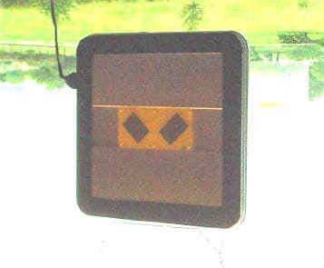
Click to zoom
Application Details
- Equipment Class
- AMP - Amplifier
- Date of Grant
- Feb 22, 2001
- Application Purpose
- Original Equipment
- Date of Application
- Feb 22, 2001
- Equipment Note
- PCS repeater model PCSSSR1900
- Frequency Range
- 1850.00000000 - 1910.00000000
- Company
- Andrew Corporation
- Country
- United States
Documents & Files
Document Text
Text extracted from the exhibit documents filed with the FCC. Open a document above to read the original.
Users Manual
INSTALLATION & OPERATION MANUAL FOR THE BETA MODELS OF THE PCS SSR Contents: 1.0 Description 1.1 Physical Configuration 1.2 Electronic Description & Block Diagram 1.3 Operational Environment 2.0 Installation Guide lines 2.1 Location 2.2 Mounting 2.3 Power Supply 3.0 Operation Guide Lines 3.1 Power / Interface Circuit Board 3.2 Stability Appendix A:PCS Frequency Band and Blocks Appendix B:Specifications Appendix C:Gain Adjustment 1.0 Description WARNING: This device complies with CFR 47, Part 24 of the FCC rules. Any modification not expressed approved by the manufacturer could invalidate the user's authority to operate the device. 1.1 Physical Configuration Figure 1 is an illustration of the 18” PCS Side to Side Repeater (SSR) indicating important features; Figure 2 is an illustration of the 12” SSR. As shown in the illustrations both SSRs have a square shape with rounded corners; both units have the same physical thickness (approximately 2”). The 18” unit weighs approximately 14.5 pounds; the 12” unit approximately 8 pounds. The 2” wide edge of both units contain 4 deep grooves separated by fins; this structure is an important electrical feature and must be keep free of extraneous material. Likewise, the central 8” square area on each face is electrically active and must be kept free of contaminating materials. Take special note that each face of the SSR has a unique electrical function and must properly oriented in operation (see section 2.0). The illustrations show the SSR without the radomes normally attached to each face. When attached the radome with the Andrew flash indicates which side should be facing the handset (mobile unit). 1.2 Electronic Description & Block Diagram The 1900 series PCS repeaters operate in the 1900 MHz PCS band. They were developed to provide more reliable coverage and/or range extension of PCS systems within sheltered structures. Specific models for each of the major US PCS sub-bands ( A, B, C, D, E & F) are offered. Pre-aligned antennas on each side of the repeaters make them easy to install and simple to operate. Designed for indoor environments, they only require a standard US 110VAC outlet for operating power. All three popular PCS systems (TDMA, CDMA & GSM) are supported. Figure 3 is an electronic block diagram of SSR internal and external circuitry. Separate antennas provide receive and transmit functions for the complementary uplink and downlink bands. In operation, the appropriate receive antenna feeds its’ signal to a band pass filter that functions to reject undesired signals and isolate the complementary band’s signal. The signal from the band pass filter feeds an amplifier with an AGC loop that limits maximum output power to approximately 100 milliwatts. The amplifier output feeds a second band pass filter functioning to limit spurious amplifier output signals and further isolate the complementary band’s signal. The complementary band’s signal path is identical to that previously described, except in the reverse direction. Both amplifiers include crude RSSI circuitry and over-current protection circuitry. 1.3 Operational Environment The SSR has been designed to operate properly in a temperature and humidity controlled indoor environment. Operation in environments where the ambient temperature is outside the 50 o -85 o F range or the relative humidity is greater than 50% may result in unsatisfactory performance. Exposure to temperatures outside the 10 o - 120 o F range or relative humidity greater than 80% may result in permanent damage to the unit. 2.0 Installation Guide Lines 2.1 Location CAUTION: In order to comply with FCC rules for rf exposure, the following must be observed: The antenna must be installed such that a minimum separation distance of 20 cm. is maintained between the antenna and any persons. Proper operation of the SSR cannot be achieved if the following installation location guide lines are not followed. The prevention of signal feedback from the transmit antenna on one side of the SSR to the same path’s receive antenna on the opposite side of the SSR is paramount to proper operation of the SSR. Any matter in the surrounding environment of the SSR will produce undesirable feedback signals. Any object with any physical dimension that is greater than 2 inches may cause undesirable signal reflections and/or refractions severe enough to cause unstable operation of the SSR. Metal objects normally cause worse reflections and/or refraction than non-metallic objects. The level of undesired reflected and/or refracted signals is directly proportional to the size of the object and inversely proportional to the distance between the SSR and the reflecting/refracting object. Obviously, a perfect “free space” environment for the SSR is the ideal location, but not practical. However, a major goal of the operating location selection process is to find a place that approximates a “free space” environment as closely as possible. A location that provides a “clear” communication link with a suitable base station signal using a typical handset is also required for proper operation of the SSR. Base station signal level at various candidate locations should be measured using the RSSI on a handset or more precise instrumentation. Experience indicates that a location with the highest base station signal level that is free of any object within a 15-20 feet radius hemisphere centered on one side of the SSR should provide suitable SSR operation. 2.2 Mounting Considerations Mounting should be accomplished with due consideration of the minimization of undesirable feedback signal discussed in section 2.1. Early product development testing used 50 lb. braided nylon cord and small “S” hooks to hang the SSR four or more feet below a convenient overhead structural member (see Figure 4). Mounting devices made of non-conductive, low dielectric constant and/or high loss tangent materials attached to any edge that minimally blocks the grooves between the fins on the …
Text truncated - open the document above for the full version.
Cover Letter(s)
REQUEST FOR CONFIDENTIALITY Andrew Corporation requests confidentiality with regard to the following documents in the filing for equipment approval identified by FCC ID. No. KUWPCSSSR1900. (1) Schematic diagrams contained in electronic file identified as schematic.pdf. It is the opinion of Andrew Corporation that disclosure of this information would result in significant loss of revenue. This information should be kept confidential for 5 years. Authorized Signature:Mano Judd, VP Company Name Andrew Corporation Address2601 Telecom Parkway Richardson, Texas 75082
ID Label/Location Info
(Size will be 1.25” high X 3” wide) 1.25" 3" Label is mounted on the downlink output side of the amplifier (facing inside of building). COMPLIES WITH CFR 47, PART 24 OF THE FCC RULES MODEL NO.: PCSSSR1900 FCC ID.: KUWPCSSSR1900
Operational Description
1.1 Physical Configuration Figure 1 is an illustration of the 18” PCS Side to Side Repeater (SSR) indicating important features; Figure 2 is an illustration of the 12” SSR. As shown in the illustrations both SSRs have a square shape with rounded corners; both units have the same physical thickness (approximately 2”). The 18” unit weighs approximately 14.5 pounds; the 12” unit approximately 8 pounds. The 2” wide edge of both units contain 4 deep grooves separated by fins; this structure is an important electrical feature and must be keep free of extraneous material. Likewise, the central 8” square area on each face is electrically active and must be kept free of contaminating materials. Take special note that each face of the SSR has a unique electrical function and must properly oriented in operation (see section 2.0). The illustrations show the SSR without the radomes normally attached to each face. When attached the radome with the Andrew flash indicates which side should be facing the handset (mobile unit). 1.2 Electronic Description & Block Diagram The 1900 series PCS repeaters operate in the 1900 MHz PCS band. They were developed to provide more reliable coverage and/or range extension of PCS systems within sheltered structures. Specific models for each of the major US PCS sub-bands ( A, B, C, D, E & F) are offered. Pre-aligned antennas on each side of the repeaters make them easy to install and simple to operate. Designed for indoor environments, they only require a standard US 110VAC outlet for operating power. All three popular PCS systems (TDMA, CDMA & GSM) are supported. Figure 3 is an electronic block diagram of SSR internal and external circuitry. Separate antennas provide receive and transmit functions for the complementary uplink and downlink bands. In operation, the appropriate receive antenna feeds its’ signal to a band pass filter that functions to reject undesired signals and isolate the complementary band’s signal. The signal from the band pass filter feeds an amplifier with an AGC loop that limits maximum output power to approximately 100 milliwatts. The amplifier output feeds a second band pass filter functioning to limit spurious amplifier output signals and further isolate the complementary band’s signal. The complementary band’s signal path is identical to that previously described, except in the reverse direction. Both amplifiers include crude RSSI circuitry and over-current protection circuitry. 1.3 Operational Environment The SSR has been designed to operate properly in a temperature and humidity controlled indoor environment. Operation in environments where the ambient temperature is outside the 50 o -85 o F range or the relative humidity is greater than 50% may result in unsatisfactory performance. Exposure to temperatures outside the 10 o -120 o F range or relative humidity greater than 80% may result in permanent damage to the unit.
RF Exposure Info
MPE Prediction for Andrew PCSSSR Repeater Maximum peak eirp: +20 dBm (100 mW) Prediction distance: 20 cm MPE limit for uncontrolled exposure at tx frequency = 1 mW/cm 2 Using the equation from page 18 of OET Bulletin 65, Edition 97-01to predict the worst-case exposure at 20 cm: 2 4R EIRP S π = where:S = power density EIRP = equivalent isotropically radiated power R = distance to the center of radiation of the antenna 2 2 /01989. 2056637.12 100 cmmW cm mW S = × = The minimum allowable separation distance to maintain the 1 mW/cm 2 limit would be: S EIRP R π4 = mW mW R 14 100 × = π 56637061.12 100 =R cmR 82.2=
Test Report
KTL Test Report No.: 0L0494RUS1 Applicant: Andrew Corporation FCC ID.: KUWPCSSSR1900 Equipment Under Test: PCS Side-to-Side Repeater In Accordance With:FCC Part 24, Subpart E Broadband PCS Repeaters Tested By: KTL Dallas Inc. 802 N. Kealy Lewisville, Texas 75057-3136 Authorized By: Tom Tidwell, RF Group Manager Date: 12/28/00 Total Number of Pages: 91 KTL Dallas FCC PART 24, SUBPART E BROADBAND PCS REPEATERS EQUIPMENT: PCS Side-to-Side Repeater FCC ID: KUWPCSSSR1900 PROJECT NO.: 0L0494RUS1 Page 2 of 91 Table of Contents Section 1. Summary of Test Results.......................................................................3 Section 2. General Equipment Specification...........................................................5 Section 3. RF Power Output.................................................................................10 Section 4. Occupied Bandwidth...........................................................................11 Section 5. Spurious Emissions at Antenna Terminals............................................38 Section 6. Field Strength of Spurious....................................................................77 Section 7. Frequency Stability..............................................................................80 Section 8. Test Equipment List.............................................................................81 ANNEX A - TEST DETAILS...............................................................................82 ANNEX B - TEST DIAGRAMS...........................................................................88 KTL Dallas FCC PART 24, SUBPART E BROADBAND PCS REPEATERS EQUIPMENT: PCS Side-to-Side Repeater FCC ID: KUWPCSSSR1900 PROJECT NO.: 0L0494RUS1 Page 3 of 91 Section 1.Summary of Test Results Manufacturer:Andrew Corporation Model No.:PCSSSR1900 Sample No.:45 General:All measurements are traceable to national standards. These tests were conducted on a sample of the equipment for the purpose of demonstrating compliance with FCC Part 24, Subpart E. New SubmissionProduction Unit Class II Permissive ChangePre-Production Unit THIS TEST REPORT RELATES ONLY TO THE ITEM(S) TESTED. THE FOLLOWING DEVIATIONS FROM, ADDITIONS TO, OR EXCLUSIONS FROM THE TEST SPECIFICATIONS HAVE BEEN MADE. See “ Summary of Test Data”. NVLAP LAB CODE: 100426-0 KTL Dallas Inc. authorizes the above named company to reproduce this report provided it is reproduced in its entirety and for use by the company’s employees only. Any use which a third party makes of this report, or any reliance on or decisions to be made based on it, are the responsibility of such third parties. KTL Dallas Inc. accepts no responsibility for damages, if any, suffered by any third party as a result of decisions made or actions based on this report. This report applies only to the items tested. KTL Dallas FCC PART 24, SUBPART E BROADBAND PCS REPEATERS EQUIPMENT: PCS Side-to-Side Repeater FCC ID: KUWPCSSSR1900 PROJECT NO.: 0L0494RUS1 Page 4 of 91 Summary Of Test Data NAME OF TEST PARA. NO. SPEC.MEAS.RESULT RF Power Output24.232100W0.1W eirpComplies Occupied Bandwidth (CDMA)24.238Input/OutputPlotsComplies Occupied Bandwidth (GSM)24.238Input/OutputPlotsComplies Occupied Bandwidth (NADC)24.238Input/OutputPlotsComplies Spurious Emissions at Antenna Terminals24.238(a)-13 dBm -13 dBm (See plots) Complies Field Strength of Spurious Emissions24.238(a) -13 dBm E.I.R.P. -16 dBmComplies Frequency Stability24.235N/AN/AN/A Footnotes: (1) Modulation characteristics were not tested since the E.U.T. processes but does not produce a modulated waveform. (2) Frequency stability was not tested since the E.U.T. processes but does not produce a modulated waveform. Measurement uncertainty for each test configuration is expressed to 95% probability. KTL Dallas FCC PART 24, SUBPART E BROADBAND PCS REPEATERS EQUIPMENT: PCS Side-to-Side Repeater FCC ID: KUWPCSSSR1900 PROJECT NO.: 0L0494RUS1 Page 5 of 91 Section 2.General Equipment Specification Supply Voltage Input: 120 VAC Frequency Bands:Downlink: Block A : 1930 – 1945 MHz Block D : 1945 – 1950 MHz Block B : 1950 – 1965 MHz Block E : 1965 – 1970 MHz Block F : 1970 – 1975 MHz Block C : 1975 – 1990 MHz Frequency Bands:Uplink: Block A : 1850 – 1865 MHz Block B : 1865 – 1870 MHz Block C : 1870 – 1885 MHz Block D : 1885 – 1890 MHz Block E : 1890 – 1895 MHz Block F : 1895 – 1910 MHz CDMAGSMNADC (G7W)(GXW)(DXW) Type of Modulation and Designator: System Gain: 45 dB / 50 dB Output Impedance: 50 ohms Max Input: -35dBm RF Output (Rated):Uplink 0.0126W @ antenna input RF Output (Rated):Downlink 0.0126W @ antenna input F1-F1F1-F2N/A Frequency Translation: SoftwareDuplexerFullband Band Selection: KTL Dallas FCC PART 24, SUBPART E BROADBAND PCS REPEATERS EQUIPMENT: PCS Side-to-Side Repeater FCC ID: KUWPCSSSR1900 PROJECT NO.: 0L0494RUS1 Page 6 of 91 Description of Modifications For Class II Permissive Change KTL Dallas FCC PART 24, SUBPART E BROADBAND PCS REPEATERS EQUIPMENT: PCS Side-to-Side Repeater FCC ID: KUWPCSSSR1900 PROJECT NO.: 0L0494RUS1 Page 7 of 91 Modifications Made During Testing KTL Dallas FCC PART 24, SUBPART E BROADBAND PCS REPEATERS EQUIPMENT: PCS Side-to-Side Repeater FCC ID: KUWPCSSSR1900 PROJECT NO.: 0L0494RUS1 Page 8 of 91 Description of Operation Separate antennas provide receive and transmit functions for the complementary uplink and downlink bands. In operation, the appropriate receive antenna feeds its’ signal to a band pass filter that functions to reject undesired signals and isolate the complementary band’s signal. The signal from the band pass filter feeds an amplifier with an AGC loop that limits maximum output power to approximately 100 milliwatts eirp (+11.5 dBm + 7.5 dBi antenna gain). The amplifier output feeds a second band pass filter functioning to limit spurious amplifier output signals and further isolate the complementary band’s signal. The complementary band’s signal path is identical to that previously described, except in the reverse direction. Both …
Text truncated - open the document above for the full version.
Test Report
Page No.Plot DescriptionSignal DirectionModulation 43In-band intermodulationULCDMA 44In-band intermodulationDLCDMA 45In-band intermodulationULCDMAHigh Gain 46In-band intermodulationDLCDMAHigh Gain 47Upper Band Edge IntermodulationULCDMA 48Upper Band Edge IntermodulationDLCDMA 49Lower Band Edge IntermodulationDLCDMA 50Lower Band Edge IntermodulationULCDMA 51Upper Band Edge IntermodulationULCDMA 52Upper Band Edge IntermodulationDLCDMA 53-56Out-of-Band Spurious with two carriersUL/DLGSM 57In-band intermodulationULGSM 58In-band intermodulationDLGSM 59In-band intermodulationULGSMHigh Gain 60In-band intermodulationDLGSMHigh Gain 61Upper Band Edge IntermodulationULGSM 62Upper Band Edge IntermodulationDLGSM 63Lower Band Edge IntermodulationDLGSM 64Lower Band Edge IntermodulationULGSM 65Upper Band Edge IntermodulationULGSM 66Upper Band Edge IntermodulationDLGSM 67-70Out-of-Band Spurious with 5 carriersUL/DLTDMA 71In-band intermodulationULTDMA 72In-band intermodulationDLTDMA 73In-band intermodulationULTDMAHigh Gain 74In-band intermodulationDLTDMAHigh Gain 75Upper Band Edge IntermodulationULTDMA 76Upper Band Edge IntermodulationDLTDMA
Test Report
Barry, Below are our responses. Regards, Tom -----Original Message----- From: Certification Manager [mailto:[email protected] ] Sent: Friday, February 16, 2001 9:01 AM To: Alma Torres Subject: Hi Alma, We have completed our review and the following issues have been identified: 1. Please point out which pages of the test report are responsive to the FCC request for a three signal IM test. If you have chosen to provide a two signal test at both the high and low edges of the bands, then please identify which plots are high and low. A summary page of which plots are responsive to which item would help us understand the data you are presenting. Reply - We performed the testing with two signals at the lower edge, the middle of the band, and the upper edge for both Uplink and Downlink directions. In some cases we performed the testing with more than two signals. We used the EIA specified upper and lower channel assignments since this is what the repeater will actually be processing. We tested intermodulation with the repeater in normal gain and in high gain modes. The difference between these two modes is that the input signal is lower for the high gain mode and the higher gain compensates to give the nominal output power. The worst-case was with maximum rf input level and lower gain. I have attached a cross reference table. <<plotcrossref.xls>> 2. Please provide a tune up procedure. Reply - There is no tune-up procedure. The gain is set at the factory according to the attached method. <<tuneup.xls>> 3. What is the adjustment power range of the unit? Reply - The output power is, of course, dependant on the received signal at the input and while consequently vary with each repeated conversation. This product employs AGC which is set to automatically reduce gain when the power output reaches +20 dBm. There is a manual gain variation available for situations where the received signals are higher than normal. This is provided to "fine tune" the coverage. In no circumstances will the rf output level be more than +20 dBm. As such, the output power is not adjusted, the gain is only adjusted to maintain the + 20 dBm output level. 5. Is five the maximum number of channels? Reply - Since the device is simply a broadband amplifier that boosts on-air signals, the maximum number of signals that it may see in operation is variable from site to site and indeed from day to day. The product only repeats the channels as it sees them. 6. We only see the antenna terminal measurements for the highest power level. Please point out the lowest power setting plots. Reply- See item 3 above. 7. The FCC have standardized the CDMA emission designator as F9W. Reply - The CDMA designator should have been listed as F9W. This is a misprint. Best regards Barry C. Quinlan Certification & Telecom Manager Curtis-Straus LLC Tom Tidwell EMC/Wireless Group Manager Nemko Dallas, Inc. Voice: 972-436-9600 FAX: 972-436-2667 e-mail: [email protected]
Test Setup Photos
KTL Dallas FCC PART 24, SUBPART E BROADBAND PCS REPEATERS EQUIPMENT: PCS Side-to-Side Repeater FCC ID: KUWPCSSSR1900 PROJECT NO.: 0L0494RUS1 Page 79 of 91 Photographs of Test Setup FRONT VIEW REAR VIEW
Contact Information
Applicant
Matthew O. Thomas(Manager, Customized Products)
Technical Contact
KTL Dallas, IncAlma Torres
[email protected]972 436 9600
802 Kealy Rd · Lewisville, Texas · United States
Non-Technical Contact
KTL Dallas, IncAlma Torres
[email protected]972 436 9600
Test Firm
Nemko Dallas, Inc.Michael Cantwell
Technical Specifications
| # | Rule Parts | Frequency Range | Power Output | Emission | Tolerance |
|---|---|---|---|---|---|
| 3 | 24 | 1.85 GHz - 1.91 GHz | 12.60 mW | DXW | Amp |
Other Applications from Andrew Corporation
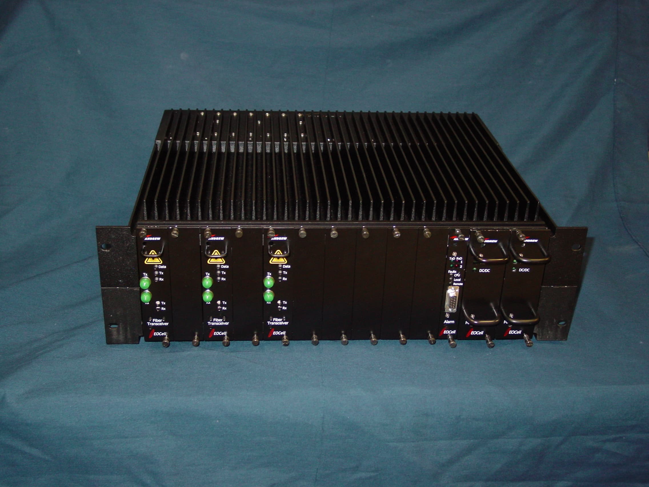
KUWEOCELL24RMT
Feb 06, 2008EOCell Transceiver System
Equipment Class
DTS - Digital Transmission System
KUW800BDA
Dec 12, 2006Downlink Booster
Equipment Class
TNB - Licensed Non-Broadcast Station Transmitter
KUWMAAIS
Aug 20, 2002Bi-Directional Amplifier
Equipment Class
AMP - Amplifier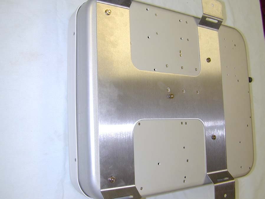
KUWINCELLERAU1
Jun 02, 2002Repeater
Equipment Class
AMP - Amplifier
KUWPCS1900
Jun 13, 2001Repeater
Equipment Class
AMP - Amplifier