L2V-STAMP1Simplex Satellite Transmitter with GPS
Spot LLC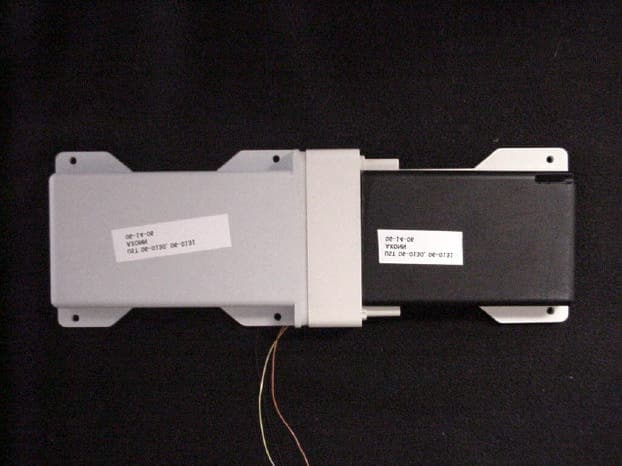
Click to zoom
Application Details
- Equipment Class
- DXX - Part 15 Low Power Communication Device Transmitter
- Date of Grant
- Jan 15, 2007
- Application Purpose
- Original Equipment
- Date of Application
- Dec 26, 2006
- Equipment Note
- Simplex Satellite Transmitter with GPS
- Frequency Range
- 2400.68800000 - 2479.80000000
- Company
- Spot LLC
- Country
- United States
Documents & Files
Document Text
Text extracted from the exhibit documents filed with the FCC. Open a document above to read the original.
Users Manual
WIRELESS DATA SOLUTIONS THAT WORK ® Axonn LLC AXTracker Users Guide – Document # 9100-0156-01 Ver 1.0 1/70 AXTracker MMT Users Manual Part Number: 9100-0156-01 Revision 1.0 Date: June 28, 2006 ® Prepared by: Axonn LLC 19349 N 12 th Street Covington, LA 70433 PH: (985) 893-1048 WIRELESS DATA SOLUTIONS THAT WORK ® Axonn LLC AXTracker Users Guide – Document # 9100-0156-01 Ver 1.0 2/70 INDEX AXTRACKER MMT USERS MANUAL ............................................................................................................................ 1 1 AXTRACKER MMT PRODUCT DESCRIPTION .................................................................................................. 4 2 AXTRACKER MMT FUNCTIONALITY................................................................................................................. 5 2.1 AXTRACKER MMT FEATURE SET OVERVIEW....................................................................................................... 5 2.2 SUPERVISORY POSITION REPORTING...................................................................................................................... 6 2.2.1 Delay to Start Interval ...................................................................................................... 7 2.2.2 Alarm Interval-Override Mode......................................................................................... 7 2.2.3 24 hour Mode....................................................................................................................8 2.2.4 Stationary Supervisory Report Rate ................................................................................. 8 2.3 ALARM INPUTS...................................................................................................................................................... 9 2.3.1 External Alarm Inputs....................................................................................................... 9 2.3.2 Motion Alarm.................................................................................................................. 10 2.3.3 Alarm Mode .................................................................................................................... 10 2.3.3.1 Interval-Override operation with Alarm Setups ......................................................... 11 2.3.4 Alarm Hysteresis & Priority ........................................................................................... 12 2.3.5 Alarm Configurations Table ........................................................................................... 12 2.3.5.1 Motion Alarm Hysteresis & Priority .......................................................................... 16 2.3.6 Alarms during Delay-to-Start interval............................................................................ 16 2.3.7 Wake from Alarm ............................................................................................................ 16 2.4 GEO-FENCING OPERATION................................................................................................................................... 16 2.4.1 Geofencing Interval-Override Operation ....................................................................... 17 2.5 GPS LOCATION FAILURE..................................................................................................................................... 18 2.6 RAS SITE AVOIDANCE......................................................................................................................................... 18 2.7 SETUP MESSAGE.................................................................................................................................................. 19 2.8 STATISTICS MESSAGE.......................................................................................................................................... 19 2.9 UNIT RESET......................................................................................................................................................... 19 2.10 DETAILED PRODUCT SPECIFICATION.................................................................................................................... 20 2.10.1 Environmental Product Specification............................................................................. 20 2.10.2 Product Battery Life ....................................................................................................... 21 3 ON-AIR MESSAGE FORMAT................................................................................................................................. 22 3.1 STATUS BYTE....................................................................................................................................................... 22 3.2 ...................................................................................................................................................................................... 23 3.3 DEFAULT (STANDARD) AXTRACKER MESSAGE................................................................................................... 24 3.3.1 Calculating Lat/Long from AXTracker MMT Messages ................................................ 24 3.3.2 Calculating Delta Lat/Long for RAS and Geofencing .................................................... 26 3.4 TRUNCATED AXTRACKER MMT MESSAGE......................................................................................................... 29 3.5 RAW PAYLOAD MESSAGE..................................................................................................................................... 29 3.6 AXTRACKER MMT SETUP MESSAGE................................................................................................................... 30 3.7 AXTRACKER MMT SETUP2 MESSAGE................................................................................................................ 31 3.8 AXTRACKER MMT STATISTICS…
Text truncated - open the document above for the full version.
Cover Letter(s)
CONFIDENTIALITY REQUEST Federal Communications Commission Equipment Authorization Branch 7435 Oakland Mills Road Columbia, MD 21046 Date: August 21, 2006 Gentlemen: Axonn LLC Inc respectfully requests confidentiality of certain materials provided with the submission of the AXTracker MMT under FCC ID: L2V-STAMP1 in accordance with FCC Regulations 0.459. The confidentiality request applies to the schematics, block diagram and Theory of Operation. The AXTracker MMT has been developed at considerable effort and expense by Axonn LLC These items are considered as Trade Secrets and therefore public access to the proprietary material could possible result in duplication of equipment that could severely damage the company's business advantage. I appreciate your assistance in this matter. Sincerely, Louis A. Feudi,Date: August 21, 2006 VP / Operations & Engineering 3505 Francis Circle Alpharetta, GA 30004 PH: 770-740-0717 Fax: 770-740-1508 www.ustech-lab.com
Cover Letter(s)
11/6/2006 Mr. Doug Noble ATCB RE: Axon, LLC FCC ID: L2V-STAMP1 Mr. Noble, Thank you for your comments in your letter of October 30, 2006. Below is my response to your comments on this application. I have included your original comments in my response. 1. External Photos must be readable and show all sides of the EUT including all ports. Please send new External Photos. The EUT has no External Ports. It is self contained and communicates for programming and commands via the 2.4 GHz transceiver. However, I have provided internal port views for the filing. Uploaded. 2. Please revise label it is unreadable. Label Location exhibit is needed for this application. Label enlarged, location added, uploaded. 3. Please upload User’s Manual exhibit. Uploaded. Please refer to 2 4 Transceiver Protocol Spec REVc1 4. Please upload Operational Description exhibit. Uploaded. Please refer to 2 4 Transceiver Protocol Spec REVc1 5. Test Report is missing Part 2 pages 13 to 36. Please submit missing portion of the Test Report. Uploaded 6. For Industry Canada the designator is listed as 3K65G1D and the 99% Bandwidth lists 365 kHz which would be 365KG1D. Please confirm which is correct. . 365 kHz is correct. Please contact me with any further questions. Sincerely, Louis A. Feudi Vice President of Operations and Engineering 3505 Francis Circle Alpharetta, GA 30004 PH: 770-740-0717 Fax: 770-740-1508 www.ustech-lab.com
Cover Letter(s)
Doug Noble From: Louis A. Feudi [[email protected]] Sent: Tuesday, December 19, 2006 12:59 PM To: [email protected] Subject: RE: www.AmericanTCB.com ATCB004103 | L2V-STAMP1 | 3989A - STAMP1 | | L2V- STAMP1_ATCB004103 Page 1 of 3Message 12/19/2006 See Answers below Thanks, Lou From: Doug Noble [mailto:[email protected]] Sent: Monday, November 27, 2006 11:23 PM To: [email protected] Subject: www.AmericanTCB.com ATCB004103 | L2V-STAMP1 | 3989A - STAMP1 | | L2V- STAMP1_ATCB004103 Regarding www.AmericanTCB.com application: ATCB ID: ATCB004103 FCC ID: L2V-STAMP1 IC: 3989A - STAMP1 TCF: Account name: usbesttech Hi Lou, Please see comments below. Please answer each question so we can get on the same page on this application. 1. Something is up with labeling...Why 2 FCC ID's and 2 Certification Numbers? Additionally, if 2 are listed, then they each should be preceded by "FCC ID: or IC:" or in the case of modular approval, the correct phrasing....Lastly if both are not fully appropriate, then one should be removed. [Louis A. Feudi] The unit contains a modular Transceiver, L2V-STX-2-1, and has an integratedSLOW hopping Transceiver. Therefore the label will state "Contains FCC ID# L2V-STX-2-1" "Contains IC:3929A-STX21" and FCC ID: L2V-STAMP1 and IC 3929A-STAMP1. The STAMP is the integrated transmitter, so the label does not state "Contains.....". 2. Test report lists a transmitter that is not listed....FCC ID: L2V-STX-2-1 Please have U.S. Tech investigate or correct. [Louis A. Feudi] The L2V-STX-2-1 is an approved Module. See 3 below. 3. It appears the other transmitter is modular approved. However the device is not properly labeled for the modular TX. [Louis A. Feudi] The label has been changed to reflect 1 ("Contains....") . 4. Test report states "spread spectrum" transmitter...Is this correct? [Louis A. Feudi] It is a slow hopping spread spectrum transmitter. However, the hop sequence does not meet FHSS requirements, and the output power is low, so the client elected to go the "Low Power transmitter" approval route. 5. Duty cycle mixes up us, ms and does not appear to factor over worse case 100 msec. Please have this review/adjusted for consistency. Given the number of incorrect application of units, it is uncertain what is correct. [Louis A. Feudi] 583 microseconds is the transmission length of time. This occurs every .75 seconds. I have changed the report to reflect 0.583 milliseconds (ms). I have calculated the duty cycle correction to 100ms. The revised report is uploaded. 6. Where is data to support duty factors? [Louis A. Feudi] An email from Axonn was provided as confirmation of the duty cycle. This has been acceptable for the last 3 applications submitted to ATCB. 7. Bandwidth should be measured with VBW >= 3* RBW (especially for 99% for IC). This does not appear correct. [Louis A. Feudi] Bandwidth was rechecked and no discernible difference was seen between 1 MHz and 3 MHz VBW. 8. Power on IC lists 84.8 dBuV/m...or 17572.8 uV ..Where is this from? Test report appears to suggest a 90.9 dBuV/m level and other levels appear around 89 dBuV. [Louis A. Feudi] The IC form has been corrected and uploaded. Thanks, Doug ____________________________________________ Douglas E. Noble NARTE (No. ATL-0142-E) Examining Compliance Engineer AmericanTCB Certification for the Wireless Industry www.atcb.com (703) 847-4700 corporate email: [email protected] corporate fax: 703/ 847-6888 direct number: 480-820-3830 / cell number: 480-747-2409 alternate email: [email protected] Page 2 of 3Message 12/19/2006 NOTICE: This E-Mail message and any attachment may contain privileged or company proprietary information. If you received this message in error, please return to the sender. Page 3 of 3Message 12/19/2006
External Photos
FCC ID: L2V-STAMP1 61 EXTERNAL PHOTOGRAPHS FCC ID: L2V-STAMP1 62 PHOTOS OF THE TESTED EUT The following photos are attached: Photo 1. Top of Battery Half and Transceiver Half, Cover On Photo 2 Bottom of Battery Half and Transceiver Half, Cover On Photo 3 Internal Connecting Ports for Battery Half and Transceiver Half FCC ID: L2V-STAMP1 63 Photo 1. Top of Battery Half and Transceiver, Cover On FCC ID: L2V-STAMP1 64 Photo 2 Bottom of Battery Half and Transceiver Half, Cover On FCC ID: L2V-STAMP1 65 Photo 3 Internal Connecting Ports for Battery Half and Transceiver Half
ID Label/Location Info
FCC ID: L2V -STAMP1 63 Photo 1. Top of Battery Half and Transceiver, Cover On
Internal Photos
FCC ID: L2V-STAMP1 61 INTERNAL PHOTOGRAPHS FCC ID: L2V-STAMP1 62 PHOTOS OF THE TESTED EUT The following photos are attached: Photo 2.Top of EUT, Cover Open Photo 3.Top of EUT, Cover Removed Photo 4.Bottom of EUT, Cover Removed Photo 6.Top of Battery Compartment, Cover Removed Photo 7.Bottom of Battery Compartment, Cover Removed Photo 8. STX2 Module Photo 9. GPS Receiver Module Photo 10. 2.4 GHz Transmitter Section FCC ID: L2V-STAMP1 63 Photo 2. Top of EUT, Cover Open FCC ID: L2V-STAMP1 64 Photo 3. Top of EUT, Cover Removed FCC ID: L2V-STAMP1 65 Photo 4. Bottom of EUT, Cover Removed FCC ID: L2V-STAMP1 66 Photo 6. Top of Battery Compartment, Cover Removed FCC ID: L2V-STAMP1 67 Photo 7. Bottom of Battery Compartment, Cover Removed FCC ID: L2V-STAMP1 68 Photo 8. STX2 Module FCC ID: L2V-STAMP1 69 Photo 9. GPS Receiver Module FCC ID: L2V-STAMP1 70 Photo 10. 2.4 GHz Transmitter Section Antenna located Bottom Left Corner
Test Report
1 Louis A. Feudi From:Eric Blanchard [[email protected]] Sent: Wednesday, October 11, 2006 11:03 AM To: [email protected] Subject: Stamp Attachments: ATT00031.html; Copy of SPEC MMT (SPP - 8520-0136-01 - C1).PDF ATT00031.html (10 KB) Copy of SPEC MMT (SPP - 8520-0... First of all, the TX duty cycle is 1.167 ms out of every 3 seconds. I missed the second "1" in the email yesterday. Our message length is 583 microseconds. We transmit each message twice out of every 3 second cycle. Each message is retransmitted on a "secondary" channel which is 8 MHz higher than the initial "primary" channel. This is the same as on the MMT 2.4 GHz protocol we had tested earlier this year. All messages are alternated between the "control" channel and a random RF channel in the 2.4 GHz band. Here's a quick example of how the Stamp might transmit. Message 1 on control channel Message 1 on control channel + 8 MHz Wait ~3 seconds Message 2 on pseudo random channel Message 2 on pseudo random channel + 8 MHz Wait ~3 seconds Message 3 on control channel Message 3 on control channel + 8 MHz ... Once again I apologize for the confusion here. 2 Also, I've attached our design specification for the MMT which contains a section on the 2.4 GHz operation. This is the exact same hardware and essentially the same firmware which is involved with the Stamp. One of the senior engineers told me that this is what could be used as a theory of operations for our 2.4 GHz radio. It doesn't really have much detail, so I can go through and create another one specifically for the Stamp is necessary. Basically the Stamp is just an external transceiver to allow communication with the MMT for setup and sensor I/O purposes. AXONN, L.L.C. Wireless Data Solutions That Work Eric Blanchard Design Engineer 19349 N. 12th Street Covington, LA 70433 P-985-893-1048, ext 318 <mailto:[email protected]> [email protected] The information contained in this e-mail message is confidential, intended only for the use of the individual or entity named above. If the reader of this e-mail is not the intended recipient, or the employee or agent responsible to deliver it to the intended recipient, you are hereby notified that any review, dissemination, distribution or copying of this communication is strictly prohibited. If you have received this e-mail in error, please contact [email protected]
Test Report
1 Axonn LLC FCC Part 15, Certification Application AXTracker MMT Frequency Hopping Transceiver UST Project: 06-0130 Issue Date: August 21, 2006 3505 Francis Circle Alpharetta, GA 30004 PH: 770-740-0717 Fax: 770-740-1508 www.ustech-lab.com 2 I certify that I am authorized to sign for the manufacturer and that all of the statements in this report and in the Exhibits attached hereto are true and correct to the best of my knowledge and belief: UNITED STATES TECHNOLOGIES, INC. (AGENT RESPONSIBLE FOR TEST): By: Name: Louis A. Feudi __________ Title: VP Operations & Engineering Date: August 21, 2006 _ Axonn LLC Corporation 19349 N. 12 th Street Covington, LA 70433 By: Name: Title: Date: This report shall not be reproduced except in full. This report may be copied in part only with the prior written approval of U.S. Technologies. The results contained in this report are subject to the adequacy and representative character of the sample provided. 3505 Francis Circle Alpharetta, GA 30004 PH: 770-740-0717 Fax: 770-740-1508 www.ustech-lab.com FCC ID: L2V-STAMP1 3 MEASUREMENT/TECHNICAL REPORT COMPANY NAME: Axonn LLC MODEL: AXTracker MMT FCC ID: L2V-STAMP1 DATE: August 21, 2006 This report concerns (check one): Original grant X Class II change_____ Equipment type: 2.4 GHz Frequency Hopping Transceiver Deferred grant requested per 47 CFR 0.457(d)(1)(ii)? yes_____ No X If yes, defer until:_________________ date N.A. agrees to notify the Commission by N.A. date of the intended date of announcement of the product so that the grant can be issued on that date. Report prepared by: United States Technologies, Inc. 3505 Francis Circle Alpharetta, GA 30004 Phone Number: (770) 740-0717 Fax Number: (770) 740-1508 FCC ID: L2V-STAMP1 4 TABLE OF CONTENTS AGENCY AGREEMENT CONFIDENTIALITY LETTER SECTION 1 GENERAL INFORMATION 1.1 Product Description 1.2 Related Submittal(s) SECTION 2 TESTS AND MEASUREMENTS 2.1 Configuration of Tested EUT 2.2 Test Facility 2.3 Test Equipment 2.4 Modifications 2.5 Antenna Description 2.6 Peak Radiated Spurious Emissions 2.7 Bandedge Requirements (Conducted and Radiated) 2.8 Minimum 20 dB Bandwidth 2.9 Power Line Conducted Emissions for Transmitter 2.10 Radiated Emissions for Digital Device & Receiver 2.11 Power Line Conducted for Digital Device & Receiver SECTION 3 LABELING INFORMATION SECTION 4 BLOCK DIAGRAM(S)/ SCHEMATIC(S) SECTION 5 PHOTOGRAPHS SECTION 6 THEORY OF OPERATION SECTION 7 USER'S MANUAL FCC ID: L2V-STAMP1 5 LIST OF FIGURES AND TABLES FIGURES 1) Test Configuration 2) Photograph(s) for Spurious and Conducted Emissions 3) Peak Radiated Spurious Emissions 4) Bandedge Compliance Antenna Conducted 5) 20 dB Bandwidth TABLES 1) EUT and Peripherals 2) Test Instruments 3) Fundamental , Peak, and Average Radiated Spurious Emissions 4) 20 dB Bandwidth 5) Conducted Emissions 6) Radiated Emissions for Digital Device and Receiver FCC ID: L2V-STAMP1 6 SECTION 1 GENERAL INFORMATION FCC ID: L2V-STAMP1 7 GENERAL INFORMATION 1.1 Product Description The Equipment Under Test (EUT) is a Axonn LLC, Model AXTracker MMT modular transceiver. The EUT is a satellite based tracking device that includes a GPS receiver, simplex satellite transmitter and a short range 2.4 GHz transceiver to communicate with wireless sensors and configuration equipment. The unit consists of : 1. An Axonn LLC, Model STX-2 simplex satellite transmitter. FCC ID: L2V-STX2- 1 2. A GPS receiver, Ublox, Model LEA-4A-0-000 3. A 2.4 GHz Frequency Hopping transmitter. The unit is designed that the Simplex satellite transmitter will not transmit simultaneously with the 2.4 GHz Frequency Hopping Transmitter, by software control. The 2.4 GHz Transmitter is extremely low power. . FCC ID: L2V-STAMP1 8 1.2 Related Submittal(s)/Grant(s) The EUT will be used to send/receive data. The transceiver presented in this report will be used with other like transceivers: The EUT is subject to the following authorizations: a) Certification as a transceiver b) Verification as a digital device The information contained in this report is presented for the certification & verification authorization(s) for the EUT. FCC ID: L2V-STAMP1 9 FCC ID: L2V-STAMP1 10 SECTION 2 TESTS AND MEASUREMENTS FCC ID: L2V-STAMP1 11 TEST AND MEASUREMENTS 2.1 Configuration of Tested System The sample was tested per ANSI C63.4, Methods of Measurement from Low-Voltage Electrical and Electronic Equipment in the Range of 9 kHz to 40 GHz (1992). Conducted and radiated emissions data were taken with the test receiver or spectrum analyzer's resolution bandwidth adjusted to 9 kHz and 120 kHz, respectively. All measurements are peak unless stated otherwise. The video filter associated with the spectrum analyzer was off throughout the evaluation process. Bock diagrams of the tested systems are shown in Figures 1a and 16. Test configuration photographs for spurious and fundamental emissions are shown in Figure 2a -g. The sample used for testing was received by U.S. Technologies on June 15, 2006 in good condition. 2.2 Test Facility Testing was performed at US Tech's measurement facility at 3505 Francis Circle, Alpharetta, GA. This site has been fully described and submitted to the FCC, and accepted in their letter marked 31040/SIT. Additionally this site has also been fully described and submitted to Industry Canada (IC), and has been approved under file number IC2982. 2.3 Test Equipment Table 2 describes test equipment used to evaluate this product. 2.4 Modifications No modifications were made by US Tech, to bring the EUT into compliance with FCC Part 15, Class B Limits for the transmitter portion of the EUT or the Class B Digital Device Requirements. FCC ID: L2V-STAMP1 12 FIGURE 1 TEST CONFIGURATION Transmitter Portion (EUT) Battery Portion (EUT) FCC ID: L2V-STAMP1 13 TABLE 1 Test Date: June 15, 16, & July 6, 2006 UST Project: 06-0130 Customer: Axonn LLC Model: AXTracker MMT EUT and Peripherals PERIPHERAL MANU. MODEL NUMBER SERIAL NUMBER FCC ID: CABLES P/D (EUT) Axonn LLC AXTracker MMT No…
Text truncated - open the document above for the full version.
Test Setup Photos
FCC ID: L2V-STAMP1 FIGURE 2a Photograph(s) for Spurious Emissions FCC ID: L2V-STAMP1 FIGURE 2b Photograph(s) for Spurious Emissions
Contact Information
Applicant
Matthew Kapral(Senior Quality Engineer)
Technical Contact
US TechLouis Feudi
[email protected]770-740-0717
3505 Fancis Circle · Alphareatta, Georgia · United States
Test Firm
US TechGeorge Yang
Technical Specifications
| # | Rule Parts | Frequency Range | Power Output |
|---|---|---|---|
| 1 | 15C | 2.40 GHz - 2.48 GHz | - |
Other Applications from Spot LLC
L2V-RX200M
Aug 14, 2024Simplex Satellite Transmitter Module with Bluetooth designed to be embedded in a customer end product
Equipment Class
TNB - Licensed Non-Broadcast Station Transmitter
L2V-TRACE2
Jan 10, 2023Satellite Asset Tracker
Equipment Class
TNB - Licensed Non-Broadcast Station Transmitter
L2V-ST150M
Oct 05, 2022Simplex Satellite Transmitter Module with Bluetooth
Equipment Class
DTS - Digital Transmission System
L2V-ST100
Jul 14, 2020Simplex Satellite Transmitter Module with Bluetooth
Equipment Class
TNB - Licensed Non-Broadcast Station Transmitter
L2V-STGR
Aug 09, 2015Globalstar STINGR
Equipment Class
TNB - Licensed Non-Broadcast Station Transmitter