L2V2100-0149User to Satellite Transmitter Module
Spot LLC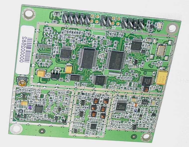
Click to zoom
Application Details
- Equipment Class
- TNB - Licensed Non-Broadcast Station Transmitter
- Date of Grant
- Nov 22, 2004
- Application Purpose
- Original Equipment
- Date of Application
- Nov 22, 2004
- Equipment Note
- User to Satellite Transmitter Module
- Frequency Range
- 1611.25000000 - 1618.75000000
- Company
- Spot LLC
- Country
- United States
Documents & Files
Document Text
Text extracted from the exhibit documents filed with the FCC. Open a document above to read the original.
Users Manual
1 Doug Noble From: Louis A. Feudi [[email protected]] Sent: Tuesday, November 23, 2004 8:57 AM To: 'Doug Noble' Cc: 'Gary Naden' Subject: RE: FCC ID: L2V2100-0149 Doug, Gary Naden, of Axonn L.L.C, has confirmed that the following statement will be placed in a visible location within the G-SENS STU operating/installation instructions: "NOTICE: This equipment complies with the FCC RF Exposure Limits. A minimum of 20 centimeters (8 inches) separation between the device and the user and all other persons should be maintained." I hope this is acceptable. Please contact me if you require further written confirmation. Lou Louis A. Feudi Sales and Operations Manager U.S. Technologies 3505 Francis Circle Alpharetta, GA 30004 Phone (770) 740-0717 Fax (770) 740-1508 [email protected]
Cover Letter(s)
FCC ID: L2V2100-0149 Report Number:04-0017 FCC Part 25, Certification Customer: Axonn, L.L.C. Model: STU 4
Cover Letter(s)
FCC ID: L2V2100-0149 Report Number:04-0017 FCC Part 25, Certification Customer: Axonn, L.L.C. Model: STU 5 CONFIDENTIALITY REQUEST Federal Communications Commission Date: September 20, 2004 Equipment Authorization Branch 7435 Oakland Mills Road Columbia, MD 21046 Gentlemen: Axonn, L.L.C.respectfully requests confidentiality of certain materials provided with the submission of the model STU under FCC ID: L2V2100-0149 in accordance with FCC Regulations 0.459. The confidentiality request applies to the following: Parts List, Theory of Operation, Schematics, These items are considered as Trade Secrets and therefore public access to the proprietary material could possible result in duplication of equipment that could severely damage the company's business advantage. I appreciate your assistance in this matter. Sincerely, Name: Louis A. Feudi Signature:_____________________ Title: Operations Manager Date: September 20, 20004
ID Label/Location Info
FCC ID: L2V2100-0149 Report Number:04-0017 FCC Part 25, Certification Customer: Axonn, L.L.C. Model: STU 69 SECTION 5 LABELING INFORMATION FCC ID: L2V2100-0149 Report Number:04-0017 FCC Part 25, Certification Customer: Axonn, L.L.C. Model: STU 70 LABEL PHOTOGRAPH
Internal Photos
FCC ID: L2V2100-0149 Report Number:04-0017FCC Part 25, Certification Customer:Axonn, L.L.C. Model:STU 63 Photo 3.Top View Motherboard and Transmitter FCC ID: L2V2100-0149 Report Number:04-0017FCC Part 25, Certification Customer:Axonn, L.L.C. Model:STU 64 Photo 4.Motherboard, Bottom – Test Unit FCC ID: L2V2100-0149 Report Number:04-0017FCC Part 25, Certification Customer:Axonn, L.L.C. Model:STU 65 Photo 5.Transmitter, Bottom FCC ID: L2V2100-0149 Report Number:04-0017FCC Part 25, Certification Customer:Axonn, L.L.C. Model:STU 66 Photo 6.Transmitter, Top
Parts List/Tune Up Info
Tune Up Procedure GMSG01 requires no Frequency tunes. The crystal is a TCXO qualified in operating range at time of manufacture. Power levels are set as below. 2.3.2 Power The output power shall have two settings selectable by a discrete input to the board, (sampled during power-up), or by command via the serial port. A jumper shall be included on the board to indicate the source of the control. If the jumper setting corresponds to the discrete input control, the discrete input PWR_LVL is sampled during power up to indicate the output power level. Discrete Control Setting (Sampled at power-up) Power Setting OpenLow GroundHigh If the jumper setting corresponds to a serial control, the power level is set according to a value set in the EEPROM. Serial port commands (See Error! Reference source not found.) can modify this EEPROM value. The output power on a 50 ohms load after the power amplifier shall be according to Table 1, Output Power Discrete Control SettingAvg Power (During 1.28 s) High 22dBm +/- 2 dB Low18 dBm +/- 2 dB Table 1, Output Power The power tolerances shall include the temperature and voltage variations as well as the manufacturing tolerances. The power measurement shall be made in a 5 MHz bandwidth centered on the carrier frequency. Closed loop power control should not be required. I/O Connector and Power/Ground connectors may be combined. 9.1 I/O & Power Connector DescriptionRS232 connection for control and test Discrete control pins for test I/O Pins Power pins ConnectorTBD Mating ConnectorTBD 13579 246810 J7-1 RTC EXTERNAL POWER IN J7-2 GROUND J7-3 LED POWER J7-4 LED CONTROL J2-1 POWER IN J2-2 POWER IN J2-3 GROUND J2-4 GROUND J2-5 DIGITAL INPUT 1 J2-6 DIGITAL INPUT 2 J2-7 SERIAL TX (INPUT) J2-8 RTS (INPUT) J2-9 SERIAL RX (OUTPUT) J2-10 CTS (OUTPUT) J4-1 TEST INPUT 1 J4-2 TEST INPUT 2 J4-3 VDIG (ICP - NOT INSTALLED IN PRODUCTION) J4-4 uC RESET (ICP - NOT INSTALLED IN PRODUCTION) J6-1 POWER LEVEL J6-2 GROUND J6-3 POWER LEVEL OVERRIDE J6-4 GROUND 2 13 4 13 24 13 24 J4J6J7 2 13 42 13 4 J3J5 J3-1 NO PIN J3-2 NO PIN J3-3 NO PIN J3-4 NO PIN J5-1 NO PIN J5-2 NO PIN J5-3 NO PIN J5-4 NO PIN J2 (TOP VIEW) Notes: • LED_GND may be connected to board ground. • The cable length between the I/O connector and the DTE will not exceed 20 cm • Unused pins of the connector will be left unconnected Note: • The OEM integrator will keep the power cable length to less than 20 cm with a minimum gauge wire gauge of 20 AWG
RF Exposure Info
FCC ID: L2V2100-0149 Report Number:04-0017 FCC Part 25, Certification Customer: Axonn, L.L.C. Model: STU SECTION 4 RF EXPOSURE INFORMATION FCC ID: L2V2100-0149 Report Number:04-0017 FCC Part 25, Certification Customer: Axonn, L.L.C. Model: STU 4.1 RF Safety Requirements to 2.1091 for Mobile Transmitters Power Output The EUT’s maximum expected output power as shown in section 2.6 is Frequency of Fundamental (MHz) Measurement (dBm) Measurement (Watt) 1618.6022.010.159 Calculating +5.5 dBi gain antenna ( worst case – vs – 4 dBi gain antenna) 0.159 * 5.5 = 0.875 W Source Based Time Averaging This information has not been included and the MPE calculations specified below do not take into consideration any duty cycle correction. MPE Calculations The limits for this unit (uncontrolled exposure) is 1.0 mW/cm 2 . Taking the RF Density Field Equation: S = (EIRP in mW)/(4πR 2 ) and solving for Field Density S Solving the above equation yields S = (875(mW)/(4*π*(20 cm) 2 ) = 0.174 mW/cm 2 The device should be installed to maintain 20 cm from humans during use. Information regarding installation and use should be contained in the users manual.
Test Report
FCC Part 25, Certification Application of the Axonn, L.L.C. Satellite Transmitter Unit (STU) Issue Date: September 20, 2004 UST Project No: 04-0017 I certify that I am authorized to sign for the manufacturer and that all of the statements in this report and in the Exhibits attached hereto are true and correct to the best of my knowledge and belief: UNITED STATES TECHNOLOGIES, INC. (AGENT RESPONSIBLE FOR TEST): By: Name: Louis A Feudi Title: Operations Manager Date: September 20, 2004 Axonn, L.L.C. 2021 Lakeshore Drive, Suite 533 New Orleans, LA 70122 By: Name: Title: Date: This report shall not be reproduced except in full. This report may be copied in part only with the prior written approval of U.S. Technologies. The results contained in this report are subject to the adequacy and representative character of the sample provided. FCC ID: L2V2100-0149 Report Number:04-0017 FCC Part 25, Certification Customer: Axonn, L.L.C. Model: STU 1 Company Name: Axonn, L.L.C Model:STU FCC ID:L2V2100-0149 Date:September 20, 20004 MEASUREMENT/TECHNICAL REPORT This report concerns (check one): Original grant X Class II change_____ Equipment type: Mobile User to Satellite Transmitter Deferred grant requested per 47 CFR 0.457(d)(1)(ii)? yes_____ No X If yes, defer until:_________________ date N.A. agrees to notify the Commission by N.A. date of the intended date of announcement of the product so that the grant can be issued on that date. Report prepared by: United States Technologies, Inc. 3505 Francis Circle Alpharetta, GA 30004 Phone Number: (770) 740-0717 Fax Number: (770) 740-1508 Report reviewed by: _________________ Louis A. Feudi Operations Manager FCC ID: L2V2100-0149 Report Number:04-0017 FCC Part 25, Certification Customer: Axonn, L.L.C. Model: STU 2 TABLE OF CONTENTS AGENCY AGREEMENT LETTER OF CONFIDENTIALITY SECTION 1 GENERAL INFORMATION 1.1Product Description 1.2Related Submittal(s) SECTION 2 TESTS AND MEASUREMENTS 2.1Configuration of Tested EUT 2.2Test Facility 2.3Test Equipment 2.4Modifications 2.5Antenna Description 2.6RF Power Output 2.7Modulation Characteristics 2.8Occupied Bandwidth 2.9Spurious Emissions at Antenna Terminals 2.10Field Strength of Spurious Radiation 2.11 Frequency Stability 2.12 Emissions from Mobile Earth Stations for Protection of Aeronautical Radionavigation- Satellite Service. SECTION 3 PHOTOGRAPHS SECTION 4 RF EXPOSURE INFORMATION SECTION 5 LABELING INFORMATION SECTION 6 BLOCK DIAGRAMS/SCHEMATICS SECTION 7 USER’S MANUAL FCC ID: L2V2100-0149 Report Number:04-0017 FCC Part 25, Certification Customer: Axonn, L.L.C. Model: STU 3 LIST OF FIGURES AND TABLES FIGURES 1)Test Configuration 2) Photograph(s) for Spurious Emissions 3) RF Power Output 4) Modulation Characteristics 5) Occupied Bandwidth 6) Spurious Emissions at Antenna Terminals 7) Emissions from Mobile Earth Stations for Protection of Aeronautical Radio Navigation- Satellite Service. 8) a – h Schematics TABLES 1)EUT and Peripherals 2) Test Instruments 3) RF Power Output 4) Field Strength of Spurious Emissions FCC ID: L2V2100-0149 Report Number:04-0017 FCC Part 25, Certification Customer: Axonn, L.L.C. Model: STU 4 SECTION 1 GENERAL INFORMATION FCC ID: L2V2100-0149 Report Number:04-0017 FCC Part 25, Certification Customer: Axonn, L.L.C. Model: STU 5 GENERAL INFORMATION 1.1Product Description The Equipment Under Test is the Axonn, L.L.C. Model STU. The EUT is a mobile “user to satellite” transmitter module that operates at the following 4 transmit frequencies: 1611.25 MHz, 1613.75 MHz, 1616.26 MHz, & 1618.75 MHz. The STU provides a modem functionality to transmit bursts of data containing user information to a satellite constellation. The satellites operate as linear transponders and the signal is redirected to a ground station where the user information is extracted and distributed. For the purpose of this test the EUT was placed into a high power (+22 dBm) constant TX mode of operation. Axonn, L.L.C. has attested that the unit is identical to the AXTracker configuration, with the same layout and parts as listed in this application. See letter on following page provided by Axonn. FCC ID: L2V2100-0149 Report Number:04-0017 FCC Part 25, Certification Customer: Axonn, L.L.C. Model: STU 6 FCC ID: L2V2100-0149 Report Number:04-0017 FCC Part 25, Certification Customer: Axonn, L.L.C. Model: STU 7 1.2Related Submittal(s)/Grant(s) The EUT is subject to the following authorizations: a) Certification as a transmitter as specified by Part 25. b) Verification to Digital Emissions as specified in Part 15. The information contained in this report is presented for the Part 25 authorization for the EUT. FCC ID: L2V2100-0149 Report Number:04-0017 FCC Part 25, Certification Customer: Axonn, L.L.C. Model: STU 8 SECTION 2 TEST AND MEASUREMENTS FCC ID: L2V2100-0149 Report Number:04-0017 FCC Part 25, Certification Customer: Axonn, L.L.C. Model: STU 9 TEST AND MEASUREMENTS 2.1 Configuration of Tested System Prepared in accordance with the requirements of the FCC Rules and Regulations Part 2 & 25. All measurements are peak unless stated otherwise. The video filter associated with the spectrum analyzer was off throughout the evaluation process. Interconnecting cables were manipulated as necessary to maximize emissions. A block diagram of the tested system is shown in Figure 1. Test configuration photographs for spurious emissions are shown in Figure 2. The sample used for testing was received by U.S. Technologies on July 16, 2002 in good condition, the EUT was re-tested with a second antenna (+5.5 dBi) on October 1, 2004. The test data was taken from AxTracker unit testing, FCC ID: L2V070878 for the +4 dBi antenna. The unit was re-tested for spurious harmonics and RF Power Output on 10/1/04, and EIRP values gained were using Table 2b. 2.2 Test Facility Testing was performed at US Tech's measurement facility at 3505 Francis Circle, Alpharetta, GA. This site has been fully described and registered by the FCC under Registration Number 91037. …
Text truncated - open the document above for the full version.
Test Report
FCC ID: L2V2100-0149 Report Number:04-0017 FCC Part 25, Certification Customer: Axonn, L.L.C. Model: STU Figure 5a. Occupied Bandwidth 50 - 100% From Edge of Authorized Bandwidth - Low FCC ID: L2V2100-0149 Report Number:04-0017 FCC Part 25, Certification Customer: Axonn, L.L.C. Model: STU Figure 5b. Occupied Bandwidth > 100% From Edge of Authorized Bandwidth - Low FCC ID: L2V2100-0149 Report Number:04-0017 FCC Part 25, Certification Customer: Axonn, L.L.C. Model: STU Figure 5c. Occupied Bandwidth 50 - 100% From Edge of Authorized Bandwidth - High FCC ID: L2V2100-0149 Report Number:04-0017 FCC Part 25, Certification Customer: Axonn, L.L.C. Model: STU Figure 5d. Occupied Bandwidth > 100% From Edge of Authorized Bandwidth - High FCC ID: L2V2100-0149 Report Number:04-0017 FCC Part 25, Certification Customer: Axonn, L.L.C. Model: STU Figure 5e. 99% Occupied Bandwidth for 26 dB removal from peak signal FCC ID: L2V2100-0149 Report Number:04-0017 FCC Part 25, Certification Customer: Axonn, L.L.C. Model: STU 2.9 Spurious Emissions at Antenna Terminals (FCC Section 2.1051) Spurious emissions appearing at the antenna terminals were measured with a spectrum analyzer by connecting the spectrum analyzer directly via a short cable to the antenna output terminals or across the antenna leads on the PCB as specified by the manufacturer. Results are shown in Figures 6a - 6p. Protection of the radio-navigation-satellite service. Mobile earth stations operating in the 1610-1626.5 MHz band shall limit out-of- band emissions in the 1574.397-1576.443 MHz band so as not to exceed an e.i.r.p. density level of -70 dB (W/MHz) averaged over any 20 ms period. The e.i.r.p. of any discrete spurious emission (i.e., bandwidth less than 600 Hz) in the 1574.397-1576.443 MHz band shall not exceed -80 dBW. FCC Minimum Standard (FCC Section 25.202(f)) For out-of-band emissions for frequencies removed from the midpoint of the assigned frequency segment by more than 250% of the authorized bandwidth (2.5 MHz), at least 43 + 10 log (P Watts ) attenuation below the mean power of the transmitter. For Lowest Channel = 43 + 10 log (0.153) = 34.8 dB For Highest Channel = 43 + 10 log (0.159) = 35.0 dB The following plots show that all emissions were at least 50.4 dB below the fundamental. Note: A 10 kHz RBW was used instead. This was deemed to be comparable to 4 kHz RBW. Additional requirement for 1574.397 - 157.443 MHz (FCC Section 25.213(b)) - 80 dBW (- 50 dBm) FCC ID: L2V2100-0149 Report Number:04-0017 FCC Part 25, Certification Customer: Axonn, L.L.C. Model: STU Figure 6a. Spurious Emissions at Antenna Terminals NOTE: Marker shows Fundamental Frequency FCC ID: L2V2100-0149 Report Number:04-0017 FCC Part 25, Certification Customer: Axonn, L.L.C. Model: STU Figure 6b. Spurious Emissions at Antenna Terminals FCC ID: L2V2100-0149 Report Number:04-0017 FCC Part 25, Certification Customer: Axonn, L.L.C. Model: STU Figure 6c. Spurious Emissions at Antenna Terminals FCC ID: L2V2100-0149 Report Number:04-0017 FCC Part 25, Certification Customer: Axonn, L.L.C. Model: STU Figure 6d. Spurious Emissions at Antenna Terminals FCC ID: L2V2100-0149 Report Number:04-0017 FCC Part 25, Certification Customer: Axonn, L.L.C. Model: STU Figure 6e. Spurious Emissions at Antenna Terminals FCC ID: L2V2100-0149 Report Number:04-0017 FCC Part 25, Certification Customer: Axonn, L.L.C. Model: STU Figure 6f. Spurious Emissions at Antenna Terminals FCC ID: L2V2100-0149 Report Number:04-0017 FCC Part 25, Certification Customer: Axonn, L.L.C. Model: STU Figure 6g. Spurious Emissions at Antenna Terminals FCC ID: L2V2100-0149 Report Number:04-0017 FCC Part 25, Certification Customer: Axonn, L.L.C. Model: STU Figure 6h. Spurious Emissions at Antenna Terminals Limit = -80 dBW = -50 dBm FCC ID: L2V2100-0149 Report Number:04-0017 FCC Part 25, Certification Customer: Axonn, L.L.C. Model: STU Figure 6i. Spurious Emissions at Antenna Terminals NOTE: Marker shows Fundamental Frequency FCC ID: L2V2100-0149 Report Number:04-0017 FCC Part 25, Certification Customer: Axonn, L.L.C. Model: STU Figure 6j. Spurious Emissions at Antenna Terminals FCC ID: L2V2100-0149 Report Number:04-0017 FCC Part 25, Certification Customer: Axonn, L.L.C. Model: STU Figure 6k. Spurious Emissions at Antenna Terminals FCC ID: L2V2100-0149 Report Number:04-0017 FCC Part 25, Certification Customer: Axonn, L.L.C. Model: STU Figure 6l. Spurious Emissions at Antenna Terminals FCC ID: L2V2100-0149 Report Number:04-0017 FCC Part 25, Certification Customer: Axonn, L.L.C. Model: STU Figure 6m. Spurious Emissions at Antenna Terminals FCC ID: L2V2100-0149 Report Number:04-0017 FCC Part 25, Certification Customer: Axonn, L.L.C. Model: STU Figure 6n. Spurious Emissions at Antenna Terminals FCC ID: L2V2100-0149 Report Number:04-0017 FCC Part 25, Certification Customer: Axonn, L.L.C. Model: STU Figure 6o. Spurious Emissions at Antenna Terminals FCC ID: L2V2100-0149 Report Number:04-0017 FCC Part 25, Certification Customer: Axonn, L.L.C. Model: STU Figure 6p. Spurious Emissions at Antenna Terminals Limit= -80 dBW = -50 dBm
Test Report
FCC ID: L2V2100-0149 Report Number:04-0017 FCC Part 25, Certification Customer: Axonn, L.L.C. Model: STU 2.10 Field Strength of Spurious Radiation (FCC Section 2.1053) Spurious emissions were evaluated from 30 MHz to 16.2 GHz at an EUT to antenna distance of 1 or 3 meters. The EUT was tested with an external power source and modulated by its own internal sources. Both a low and high channel were tested. The EUT was placed on an open area test site and the spurious emissions tested as stipulated by EIT/TIA-603: 1992 section 2.2.12. Measurements for 30 to 1000 MHz were made with the analyzer's bandwidth set to 120 kHz. Measurements above 1 GHz were made with the analyzer's bandwidth set to 1 MHz. The worse case results are shown in Table 4. FCC Minimum Standard (FCC Section 25.202(f)) For out-of-band emissions for frequencies removed from the midpoint of the assigned frequency segment by more than 250% of the authorized bandwidth (2.5 MHz), at least 43 + 10 log (P Watts ) attenuation below the mean power of the transmitter. For Lowest Channel = 43 + 10 log (0.153) = 34.8 dB For Highest Channel = 43 +10 log (0.159) = 35.0 dB FCC ID: L2V2100-0149 Report Number:04-0017 FCC Part 25, Certification Customer: Axonn, L.L.C. Model: STU TABLE 4a FIELD STRENGTH OF SPURIOUS RADIATION Antenna with +4 dBi gain Limit: 43 + 10 log (P Watts ) = 43 + 10 log (0.1462) = 34.6 dB Worse Case Mode = High Channel Frequency (MHz) Polarity (H or V) Corrected Substitution Level Relative to Dipole (dBm) Attenuated Level Below Carrier Power (dB) 3223V-34.956.5 SAMPLE CALCULATION: Attenuated Level Below Carrier Power = 10 log (TX Power in mW) – Corrected Substitution Level (dBm) 10 log (146.2) - -34.9 = 56.5 Test Date: June 26, 2003 Tester Signature: Name: David Blethen FCC ID: L2V2100-0149 Report Number:04-0017 FCC Part 25, Certification Customer: Axonn, L.L.C. Model: STU TABLE 4b FIELD STRENGTH OF SPURIOUS RADIATION Antenna with +5.5 dBi gain Limit: 43 + 10 log (P Watts ) = 43 + 10 log (0.153) = 34.8 dB Channel Frequency (MHz) Polarity (H or V) Corrected Substitution Level Relative to Dipole (dBm) Attenuated Level Below Carrier Power (dB) Low4.83368V-53.1175.0 High4.85618H-51.8673.9 All other Harmonic frequencies were below 20 dB of the FCC Limits. SAMPLE CALCULATION: Attenuated Level Below Carrier Power = 10 log (TX Power in mW) – Corrected Substitution Level (dBm) 10 log (0.153) –53.11 = 75.0 Test Date: October 1, 2004 Tester Signature: Name: David Blethen FCC ID: L2V2100-0149 Report Number:04-0017 FCC Part 25, Certification Customer: Axonn, L.L.C. Model: STU 2.11 Frequency Stability (FCC Section 2.1055 and 25.202(d)) The frequency tolerance of the carrier signal was measured by while ambient temperature was varied from -30 to 50 degrees centigrade. The frequency tolerance was verified at 10 degree increments. Additionally, the supply voltage was varied from 85% to 115% of the nominal value (except for hand carried, battery powered equipment which was additionally measured at battery endpoint). FCC Minimum Standard None FCC ID: L2V2100-0149 Report Number:04-0017 FCC Part 25, Certification Customer: Axonn, L.L.C. Model: STU FCC VerificationTest Results Reviewed By: Axonn Model G-SENS STU Frequency Stability vs. Temperature (At Startup) Timothy R. Johnson MeasuredNARTE Certified Engineer TemperatureFrequencyDeviation (degrees C)(MHz)(ppm) -301611.2548003.0 -201611.2546052.9 -101611.2550923.2 01611.2534942.2 101611.2537622.3 201611.2539172.4 301611.2533702.1 401611.2534382.1 501611.2548053.0 Actual TX Frequency was:1611.250MHz Maximum Deviation = 0.001% or 10 ppm Frequency Stability vs. Temperature (At Startup) -20.0 -15.0 -10.0 -5.0 0.0 5.0 10.0 15.0 20.0 -30-10103050 Temperature De via tio n (pp m) Measured Results Limit FCC ID: L2V2100-0149 Report Number:04-0017 FCC Part 25, Certification Customer: Axonn, L.L.C. Model: STU FCC VerificationTest Results Reviewed By: Axonn Model G-SENS STU Frequency Stability vs. Temperature (2 minutes after startup) Timothy R. Johnson MeasuredNARTE Certified Engineer TemperatureFrequencyDeviation (degrees C)(MHz)(ppm) -301611.2547002.9 -201611.2545612.8 -101611.2550363.1 01611.2533462.1 101611.2537302.3 201611.2539892.5 301611.2533662.1 401611.2536092.2 501611.2547332.9 Actual TX Frequency was:1611.250MHz Maximum Deviation = 0.001% or 10 ppm Frequency Stability vs. Temperature (At Startup) -20.0 -15.0 -10.0 -5.0 0.0 5.0 10.0 15.0 20.0 -30-10103050 Temperature Deviation (ppm) Measured Results Limit FCC ID: L2V2100-0149 Report Number:04-0017 FCC Part 25, Certification Customer: Axonn, L.L.C. Model: STU FCC VerificationTest Results Reviewed By: Axonn Model G-SENS STU Frequency Stability vs. Temperature (5 minutes after startup) Timothy R. Johnson MeasuredNARTE Certified Engineer TemperatureFrequencyDeviation (degrees C)(MHz)(ppm) -301611.2549003.0 -201611.2546132.9 -101611.2550403.1 01611.2533742.1 101611.2537572.3 201611.2539532.5 301611.2533182.1 401611.2535542.2 501611.2546732.9 Actual TX Frequency was:1611.250MHz Maximum Deviation = 0.001% or 10 ppm Frequency Stability vs. Temperature (At Startup) -20.0 -15.0 -10.0 -5.0 0.0 5.0 10.0 15.0 20.0 -30-10103050 Temperature Deviation (ppm) Measured Results Limit FCC ID: L2V2100-0149 Report Number:04-0017 FCC Part 25, Certification Customer: Axonn, L.L.C. Model: STU FCC VerificationTest Results Reviewed By: Axonn Model G-SENS STU Frequency Stability vs. Temperature (10 minutes after startup) Timothy R. Johnson MeasuredNARTE Certified Engineer TemperatureFrequencyDeviation (degrees C)(MHz)(ppm) -301611.2550503.1 -201611.2545812.8 -101611.2550363.1 01611.2533982.1 101611.2537732.3 201611.2539732.5 301611.2533462.1 401611.2535622.2 501611.2546612.9 Actual TX Frequency was:1611.250MHz Maximum Deviation = 0.001% or 10 ppm Frequency Stability vs. Temperature (At Startup) -20.0 -15.0 -10.0 -5.0 0.0 5.0 10.0 15.0 20.0 -30-10103050 Temperature Deviation (ppm) Measured Results Limit FCC ID: L2V2100-0149 Report Number:04-0017 FCC Part 25, Certification…
Text truncated - open the document above for the full version.
Test Report
Voltages and Currents in Final Amplification Circuit Voltages are all 5 VDC and below. The amplifier runs on 5 VDC with peak run current of 500 mA however normal operating current is 375 mA at room temperature. The final power amplifier contains active feedback, which prevents current run-away due to VSWR mismatch (i.e. open or short circuit).
Contact Information
Applicant
Matthew Kapral(Senior Quality Engineer)
Technical Contact
US TechLou Feudi
[email protected]770-740-0717
3505 Francis Circle · Alpharetta, Georgia · United States
Test Firm
US TechSandy McEnery
Technical Specifications
| # | Rule Parts | Frequency Range | Power Output | Emission | Tolerance |
|---|---|---|---|---|---|
| 1 | 25 | 1.61 GHz - 1.62 GHz | 159.00 mW | 2M31G1D | 10.0000000000 ppm |
Other Applications from Spot LLC
L2V-RX200M
Aug 14, 2024Simplex Satellite Transmitter Module with Bluetooth designed to be embedded in a customer end product
Equipment Class
TNB - Licensed Non-Broadcast Station Transmitter
L2V-TRACE2
Jan 10, 2023Satellite Asset Tracker
Equipment Class
TNB - Licensed Non-Broadcast Station Transmitter
L2V-ST150M
Oct 05, 2022Simplex Satellite Transmitter Module with Bluetooth
Equipment Class
DTS - Digital Transmission System
L2V-ST100
Jul 14, 2020Simplex Satellite Transmitter Module with Bluetooth
Equipment Class
TNB - Licensed Non-Broadcast Station Transmitter
L2V-STGR
Aug 09, 2015Globalstar STINGR
Equipment Class
TNB - Licensed Non-Broadcast Station Transmitter