L2VAX550Low Power Spread Spectrum Module
Spot LLC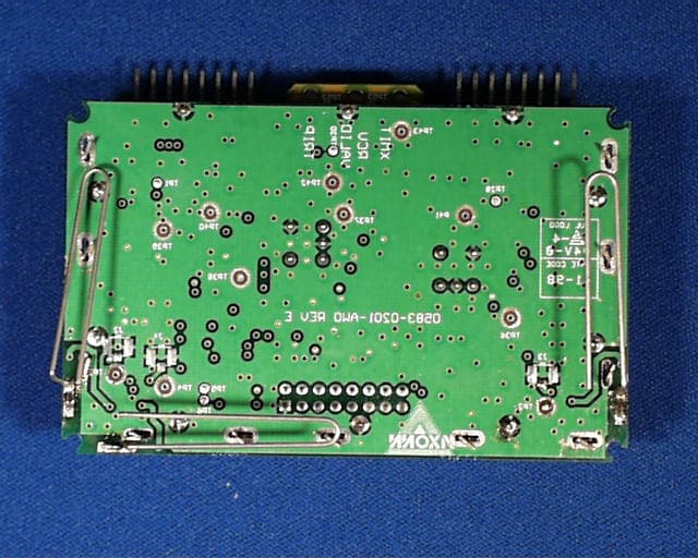
Click to zoom
Application Details
- Equipment Class
- DSS - Part 15 Spread Spectrum Transmitter
- Date of Grant
- Jun 14, 2001
- Application Purpose
- Original Equipment
- Date of Application
- Jun 12, 2001
- Equipment Note
- Low Power Spread Spectrum Module
- Frequency Range
- 905.65000000 - 923.65000000
- Company
- Spot LLC
- Country
- United States
Documents & Files
Document Text
Text extracted from the exhibit documents filed with the FCC. Open a document above to read the original.
Users Manual
FCC ID: L2VAX550 SECTION 10 USER'S MANUAL FCC ID: L2VAX550 FCC ID: L2VAX550
Cover Letter(s)
L.L.C. 2021 Lakeshore Drive · Suite 500 · New Orleans, Louisiana 70122 · (504) 282-8119 · FAX (504) 304-2427 May 31, 2001 Timothy Johnson U.S. Technologies 3505 Francis Circle Alpharetta, GA 30004 Dear Tim: This letter is in response to your request for additional information concerning the modular application of the attached filing (FCC ID L2VAX550). The AX550 module has shielding on both the RF and digital circuit cards. The bottom layer of the RF card (this is the external layer of the board, adjacent to the atennas) is a ground plane, which also provides shielding for the device. All data inputs are isolated with resistors. The 4 alarm inputs, in addition to being isolate, are also pulled to VCC with 2.7 Mohm resistors. Best Regards, David Alley Axonn L.L.C.
Cover Letter(s)
American Telecommunications Certification Body Inc. 6731 Whittier Ave, McLean, VA 22101 June 1, 2001 RE: Axonn Corp. FCC ID: FCC ID L2VAX550 I am in receipt of the response letter of May 31, 2001. The explanation provided is sufficient for my RF shielding question. I still have some concerns about data buffering. The big test for this is what would happen in an over- modulated condition. 1.) Please describe what effect if any will occur to the transmitted emission envelope with unusually high input signal levels. As an example, if the equipment is designed to accept a 1V p-p input data stream, what will happen if the input signal is increased to 10V p-p? 2.) Please describe what effect if any will occur to the transmitted emission envelope with unusually fast input data rates. As an example, if the maximum design data rate is 9600bps, what will happen if the serial input to the device is increased to 19,200bps? William H. Graff Examining Engineer President and Director of Engineering mailto:[email protected] The items indicated above must be submitted before processing can continue on the above referenced application. Failure to provide the requested information may result in application termination. Correspondence should be considered part of the permanent submission and may be viewed from the Internet after a Grant of Equipment Authorization is issued. Please do not respond to this correspondence using the email reply button. In order for your response to be processed expeditiously, you must submit your documents through the AmericanTCB.com website. Also, please note that partial responses increase processing time and should not be submitted. Any questions about the content of this correspondence should be directed to the sender.
Cover Letter(s)
American Telecommunications Certification Body Inc. 6731 Whittier Ave, McLean, VA 22101 May 24, 2001 RE: Axonn L.L.C FCC ID: L2VAX550 This is certainly a complex application because two laboratories were involved. The following questions need to be resolved. These are the obvious discrepancies. 1.) The Confidentiality request must be on Applicant letterhead Please resolve 2.) There is no Agent Authorization included with the filing. 3.) Please provide manufacturers attestation that the “paper clip” antennas are the only ones that will be utilized with this device. The Grant of Equipment Authorization shall reflect this. 4.) It would be proper to include a cover letter for this product, including the Note : from the bottom of the operational description and request for modular approval. 5.) Power output is listed as 0.1W. Please be advised that this at the upper bound of what a TCB is permitted to approve in the 2400 – 2483.5 MHz spread spectrum band under current rules. Source based time averaging may be appropriate for this device. 6.) We are also concerned about how this product will be used. Please define it as fixed, mobile, or portable. Also, if portable, carefully define it’s operation with regard to use near extremities or the body. In addition, the following has been asked of the FCC. Until I receive guidance on these questions I cannot move forward: 1.) What is the definition of "data buffering? Does that include resistive isolation of the inputs? Or is it more complex and involve the streaming of data into and out of a memory circuit? 2.) Is RF shielding required to extend to the bottom of the PC board? Is, in essence, the product expected to be a sealed can top and bottom with no exposed PCB contacts or vias other than those necessary to connect antennas, power and data I/O lines? William H. Graff Examining Engineer President and Director of Engineering mailto:[email protected] The items indicated above must be submitted before processing can continue on the above referenced application. Failure to provide the requested information may result in application termination. Correspondence should be considered part of the permanent submission and may be viewed from the Internet after a Grant of Equipment Authorization is issued. Please do not respond to this correspondence using the email reply button. In order for your response to be processed expeditiously, you must submit your documents through the AmericanTCB.com website. Also, please note that partial responses increase processing time and should not be submitted. Any questions about the content of this correspondence should be directed to the sender.
Cover Letter(s)
FCC ID: L2VAX550 CONFIDENTIALITY REQUEST Federal Communications Commission Date: 5/4/01 Equipment Authorization Branch 7435 Oakland Mills Road Columbia, MD 21046 Gentlemen: Axonn L.L.C. respectfully requests confidentiality of certain materials provided with the submission of the AX-550 under FCC ID: L2VAX550 in accordance with FCC Regulations 0.459. The confidentiality request applies to the schematics and block diagrams contained in Section 7. The AX-550 has been developed at considerable effort and expense by Axonn L.L.C. These items are considered as Trade Secrets and therefore public access to the proprietary material could possible result in duplication of equipment that could severely damage the company's business advantage. I appreciate your assistance in this matter. Sincerely, Name: Timothy R. Johnson Signature: Title: Engineering Manager Date: 5/4/2001
Cover Letter(s)
June 12, 2001 Federal Communications Commission Equipment Authorization Division 7435 Oakland Mills Road Columbia, MD 21046 Dear Sirs, The enclosed application for FCC ID: L2VAX550 is being submitted on behalf of Axonn L.L.C. Axonn L.L.C. respectfully request that this product be certified as a modular Transceiver filing to part 15.247. Please refer to the following information with respect to this product.: NOTE: The EUT was previously certified with the FCC under FCC ID Number: L2VAX-551. Although all Modular TX issues were addressed in this filing, the final grant did not reflect this fact. Since Axonn L.L.C. wishes to obtain a grant for this product that states that the unit is modular, the unit is being submitted under a new FCC ID Number (FCC ID: L2VAX-550). Most of the information within this filing is being provided from the original submittal to the FCC. Since this information originated from a different laboratory, any unclear issues or new requirements have been addressed and included with this submittal. I hope that you find that this information fulfills the necessary FCC requirements for the Part 15 Certification requirements. If you have any questions, please feel free to contact me at (770)741- 0717. Sincerely, Timothy R. Johnson Engineering Manager
Cover Letter(s)
L.L.C. 2021 Lakeshore Drive · Suite 500 · New Orleans, Louisiana 70122 · (504) 282-8119 · FAX (504) 304-2427 June 14, 2001 Timothy Johnson U.S. Technologies 3505 Francis Circle Alpharetta, GA 30004 Dear Tim: This letter is in response to your request for additional information concerning the modular application of the attached filing (FCC ID L2VAX550). Questions were raised concerning input data that did not conform to Axonn’s specifications; specifically, if the input data either exceeded the rated voltage input levels of the device, or if the input data exceeded the transfer (baud) rate of the device. All input messages for the device are input to a microprocessor; the microprocessor must be able to correctly identify a valid message prior to any transmission. Input values that exceed the recommended voltage values will damage the device and prevent the device from transmitting. Input messages that exceed the recommended transfer rate will not be understood by the microcontroller, resulting in a data query by the microcontroller, but no message will be transmitted. Best Regards, David Alley Axonn L.L.C.
External Photos
Photograph 1: AX551 (Top View) Photograph 2: AX551 (Bottom View)
ID Label/Location Info
FCC ID: L2VAX550 SECTION 6 LABELING INFORMATION FCC ID: L2VAX550
Internal Photos
Photograph 3: DPS Credit Card Digital CKT (Bottom View) Photograph 4: DPS Credit Card Digital CKT (Top View) Photograph 5: DSSS Credit Card Transceiver RF (Top View) Photograph 6: DSSS Credit Card Transceiver RF (Bottom View)
Operational Description
FCC ID: L2VAX550 GENERAL INFORMATION 1.1Product Description The Equipment Under Test (EUT) is the Axonn L.L.C., Model AX-550 Transmitter. The EUT transmits signals and receives signals from various Itero designed and 3 rd party transmitters, receivers, and transceivers. The transceiver communicates to a host device via serial data communications, sending demodulated data from the receiver digital section to the host device for further processing. The EUT utilizes direct sequence spread spectrum technology for communication in the 902-928 MHz band at approximately 100 mW output power. This application is being submitted in order to approve the EUT as a stand-alone TX module. NOTE: The EUT was previously certified with the FCC under FCC ID Number: L2VAX- 551. Although all Modular TX issues were addressed in this filing, the final grant did not reflect this fact. Since Axonn L.L.C. wishes to obtain a grant for this product that states that the unit is modular, the unit is being submitted under a new FCC ID Number (FCC ID: L2VAX-550). Most of the information within this filing is being provided from the original submittal to the FCC. Since this information originated from a different laboratory, any unclear issues or new requirements have been addressed and included with this submittal.
RF Exposure Info
FCC ID: L2VAX550 SECTION 9 RF EXPOSURE INFORMATION FCC ID: L2VAX550 9.1 RF Safety Requirements to 2.1091 for Mobile Transmitters The EUT is being submitted for modular approval. However, due to the design of the transmitter and low duty cycle the manufacturer only expects the EUT to be used in mobile environment. The unit under evaluation has an integral antenna of –4.5 dBi gain with a calculated output power output of 0.100 Watts at the antenna terminals. Taking into consideration the gain of the antenna, the corrected EIRP is 35.5 mW. Source Based Time Averaging Source based time averaging has not been applied since the calculated MPE easily meets the 20 cm requirement for mobile devices without factoring in the source based time averaging. MPE Calculations The MPE calculations are shown as follows: The limits for this unit (uncontrolled exposure) are 0.61 mW/cm 2 . Taking the RF density Field Equation: S = EIRP (mW)/(4πR 2 ) and solving for Distance R R = SQRT(EIRP (mW)/(S4π)) Plugging in data yields R (cm) = SQRT (35.5 (mw)/(0.61 (mW/cm 2 )*4*π) ) = 4.6 cm The RF Density equation shows that the minimum separation distance to be 4.6 cm. Since the EUT is considered by the manufacture to be a mobile unit, which by definition specifies that the antenna distance is greater than 20 cm, the manual therefore incorporates a caution statement that states that the unit should only be used when a separation of 20 cm is maintained between the antenna and users. This ensures compliance with the MPE requirements.
Test Report
Page 1 of 41 SSCWIdledelta SNR22.47844.66639517.812 Noise10.0910717.626987.816656-7.535902 Signal32.2986822.2700510.02864 Signal32.2986822.27005 Noise7.8166567.816656 SNR24.4820214.4533910.02864 Summary Page Page 2 of 41 COMTimeTyPCIDTxAlarmsKOCrSgNsSNR 209:01:26S0D2D3B2D0E 209:01:26S0C2D3A2D0D 209:01:26S0A2D382D0B 209:01:27S072D352D08 209:01:27S0F2D3D2D10 209:01:27S0D2D3B2D0E 209:01:27S092D372D0A 209:01:27S0C2D3A2D0D 209:01:27S0B2D382D0B 209:01:27S102D3E2D11 209:01:27S5C2D2C2D00 209:01:28S082D362D09 209:01:28S0E2D3C2D0F 209:01:28S0C2D3A2D0D 209:01:28S072D352D08 209:01:28S0F2D3D2D10 209:01:28S072D352D08 209:01:28S0C2D3A2D0D 209:01:28S062D342D07 209:01:29S0E2D3C2D0F 209:01:29S022D302D03 209:01:29S102D3E2D11 209:01:29S082D362D09 209:01:29S0B2D382D0B 209:01:29S0C2D3A2D0D 209:01:29S0C2D3A2D0D 209:01:30S0E2D3C2D0F 209:01:30S0E2D3C2D0F 209:01:30S0D2D3B2D0E 209:01:30S0E2D3C2D0F 209:01:30S062B332B08 209:01:30S0A2D382D0B 209:01:30S052D332D06 209:01:31S072D352D08 209:01:31S072D352D08 209:01:31S052D332D06 209:01:31S0D2D3B2D0E 209:01:31S0E2D3C2D0F 209:01:31S082D362D09 209:01:31S092D372D0A 209:01:32S082D362D09 209:01:32S0D2D3B2D0E 209:01:32S072D352D08 209:01:32S082D362D09 209:01:32S0E2D3C2D0F 209:01:32S062D342D07 209:01:32S062D342D07 209:01:32S0D2D3B2D0E 209:01:33S062D342D07 Data where transmit spreading is turned off. Page 3 of 41 209:01:33S032D312D04 209:01:33S0C2D3A2D0D 209:01:33S082D362D09 209:01:33S0C2D3A2D0D 209:01:33S0E2D3C2D0F 209:01:33S072D352D08 209:01:34S072D352D08 209:01:34S0B2D382D0B 209:01:34S082D362D09 209:01:34S092D372D0A 209:01:34S0E2D3C2D0F 209:01:34S072D352D08 209:01:34S082D362D09 209:01:35S0C2D3A2D0D 209:01:35S102D3E2D11 209:01:35S0A2D382D0B 209:01:35S072D352D08 209:01:35S0A2D382D0B 209:01:35S062D342D07 209:01:35S122D402D13 209:01:36S0C2D3A2D0D 209:01:36S0F2D3D2D10 209:01:36S0E2D3C2D0F 209:01:36S092D372D0A 209:01:36S0E2D3C2D0F 209:01:36S0D2D3B2D0E 209:01:36S062D342D07 209:01:37S0F2D3D2D10 209:01:37S072D352D08 209:01:37S0C2D3A2D0D 209:01:37S0B2D382D0B 209:01:37S0E2D3C2D0F 209:01:37S062D342D07 209:01:37S0A2D382D0B 209:01:38S0E2D3C2D0F 209:01:38S102D3E2D11 209:01:38S102D3E2D11 209:01:38S0B2D382D0B 209:01:38S0E2D3C2D0F 209:01:38S072D362D09 209:01:38S062D342D07 209:01:39S092D372D0A 209:01:39S102D3E2D11 209:01:39S052D332D06 209:01:39S0C2D3A2D0D 209:01:39S5A2D2B2D00 209:01:39S112D3F2D12 209:01:39S082D362D09 209:01:40S0A2D382D0B 209:01:40S052D332D06 209:01:40S082D362D09 209:01:40S022D302D03 Page 4 of 41 209:01:40S082D362D09 209:01:40S0B2D382D0B 209:01:40S082D362D09 209:01:41S0D2D3B2D0E 209:01:41S042D322D05 209:01:41S062D342D07 209:01:41S082D362D09 209:01:41S062D342D07 209:01:41S082D362D09 209:01:41S0D2D3B2D0E 209:01:41S102D3E2D11 209:01:42S082D362D09 209:01:42S0E2D3C2D0F 209:01:42S0E2D3C2D0F 209:01:42I2D 209:01:42S062D342D07 209:01:42S0F2D3D2D10 209:01:43S062D342D07 209:01:43S062D342D07 209:01:43S0F2D3D2D10 209:01:43S0D2D3B2D0E 209:01:43S102D3E2D11 209:01:44S072D352D08 209:01:44S102D3E2D11 209:01:44S0C2D3A2D0D 209:01:44S0E2D3C2D0F 209:01:44S0B2D382D0B 209:01:44S082D362D09 209:01:44S072D352D08 209:01:45S0C2D3A2D0D 209:01:45S0A2D382D0B 209:01:45S14283D2815 209:01:45S102D3E2D11 209:01:45S082D362D09 209:01:45S092D372D0A 209:01:45S072D352D08 209:01:46S082D362D09 209:01:46S0C2D3A2D0D 209:01:46S0C2D3A2D0D 209:01:46S102D3B2D0E 209:01:46S042D322D05 209:01:46S0F2D3D2D10 209:01:46S082D362D09 209:01:47S092D372D0A 209:01:47S102D3E2D11 209:01:47S092D372D0A 209:01:47S0A2D382D0B 209:01:47S102D3E2D11 209:01:47S072D352D08 209:01:47S0E2A382A0E 209:01:47S092D372D0A 209:01:48S102D3E2D11 Page 5 of 41 209:01:48S102D3E2D11 209:01:48S092D372D0A 209:01:48S082D362D09 209:01:48S042D3E2D11 209:01:48S092D372D0A 209:01:49S082D362D09 209:01:49S0E2D3C2D0F 209:01:49S062D342D07 209:01:49S092D372D0A 209:01:49S092D372D0A 209:01:49S082D362D09 209:01:49S072D352D08 209:01:50S0B2D382D0B 209:01:50S0C2D3A2D0D Page 6 of 41 COMTimeTyPCIDTxAlarmsKOCrSgNsSNR 209:02:31DFF123E--X1134194E1935 209:02:31DFF123E--X123F13541341 209:02:32DFF123E--X1337174F1B34 209:02:33DFF123E--X143918521C36 209:02:33DFF123E--X15301A4A1A30 209:02:34DFF123E--X16351B511E33 209:02:34DFF123E--X17361E562036 209:02:35DFF123E--X1837174F1B34 209:02:35DFF123E--X193A1A541D37 209:02:36DFF123E--X1A37144D1934 209:02:36DFF123E--X1B371B531B38 209:02:37DFF123E--X1C3018491C2D 209:02:38DFF123E--X1D3B18531B38 209:02:38DFF123E--X1E3719501937 209:02:39DFF123E--X1F381A541A3A 209:02:39DFF123E--X003C1754173D 209:02:40DFF123E--X013C17531B38 209:02:40DFF123E--X023E15551540 209:02:41DFF123E--X033D18551B3A 209:02:41DFF123E--X04311C4E1C32 209:02:42DFF123E--X053718501838 209:02:42DFF123E--X06371A521D35 209:02:43DFF123E--X073A15501A36 209:02:44DFF123E--X0834194E1935 209:02:44DFF123E--X093C1552153D 209:02:45DFF123E--X0A3C18541B39 209:02:45DFF123E--X0B371B531B38 209:02:46DFF123E--X0C3817501739 209:02:46DFF123E--X0D3D1956193D 209:02:47DFF123E--X0E3619501D33 209:02:47DFF123E--X0F3818511839 209:02:48DFF123E--X10361A521D35 209:02:49DFF123E--X113819521939 209:02:49DFF123E--X1238164F1A35 209:02:50DFF123E--X133C17541B39 209:02:50DFF123E--X1435194F1C33 209:02:51DFF123E--X153C1855183D 209:02:51DFF123E--X163A18531C37 209:02:52DFF123E--X17371C551C39 209:02:52DFF123E--X183B1552153D 209:02:53DFF123E--X193B144F1936 209:02:53DFF123E--X1A3D1855183D 209:02:54DFF123E--X1B3718501838 209:02:55DFF123E--X1C3E1756173F 209:02:55DFF123E--X1D36154D1538 209:02:56DFF123E--X1E381B541B39 209:02:56DFF123E--X1F3E1554153F 209:02:57DFF123E--X003818511B36 209:02:57DFF123E--X013C1854183C Data where transmit spreading is turned on. Page 7 of 41 209:02:58DFF123E--X0237184F1B34 209:02:58DFF123E--X033E1856183E 209:02:59DFF123E--X043919531C37 209:03:00DFF123E--X053817501B35 209:03:00DFF123E--X063C1855183D 209:03:01DFF123E--X073A1752173B 209:03:01DFF123E--X083A1852183A 209:03:02DFF123E--X09381852183A 209:03:02DFF123E--X0A3C1854183C 209:03:03DFF123E--X0B3D1553193A 209:03:03DFF123E--X0C3B1552153D 209:03:04DFF123E--X0D311F512130 209:03:05DFF123E--X0E3E15551540 209:03:05DFF123E--X0F3B1954193B 209:03:06DFF123E--X10341B501B35 209:03:06DFF…
Text truncated - open the document above for the full version.
Test Report
An Axonn spread spectrum receiver and the Axonn Artist tool was used to acquire the data for this file. The AX551 transceiver was connected to the serial port of a PC, and Artist acquires messages from the transceiver and formats the message data. AX551 transceivers are capable of measuring multiple RF signal level parameters. These include transmitter correlation processing gain, key-off signal level, Power correlation signal level, Post correlation noise signal level, and calculated Signal to Noise Ratio. The associated Excel file (process gain.xls) has a lot of data and calculations spread among 11 workbooks. The first 3 workbooks are collected data, and the remaining 8 workbooks are calculations base upon the first three workbooks. Explanations of the columns in the first three workbooks (SS, CW, Idle): The first column (COM) shows which com port of the PC is attached to the AX551 transceiver. COM port 2 was used in collecting all of the data for this file. The second column (Time) shows the time when the message was received. The third column (Ty) indicates the status of the received message. "D" indicates that a good message was received. "S" is one of the debug flags that indicates that there was an error in the received message. "I" indicates that the AX551 transceiver was idle (no messages were received). The fourth and fifth columns (PC and ID) are the Property Code and Identification number of the received transmitter. The sixth column (Tx) indicates the type of message transmitted by the transmitter. The "Alarms" field is several characters wide and indicates the status of various alarm bits in the transmitter. The eight column is unmarked but contains additional alarm information. The ninth column (SN) contains sequence number information. Axonn transmitters embed an incrementing sequence count value into every sent message. This gives the receiver the ability to tell if a messages was lost. A note about the remaining columns. The remaining columns show signal data that is measured by the AX551 transceiver. The values 0-255 span a dynamic range of 100 dB. To convert the displayed value (referred to as "Hex counts") to power in dB, divide the displayed Hex count value by 2.56 The tenth column (KO) indicates the Key-Off value. Axonn transmitters incorporate OOK (on-off keying) to modulate data. The KO value indicates the difference between a key-on value and a key-off value. These values are not used in the processing gain calculations. The next column (Cr) shows the increase in signal level due to spread spectrum correlation. These values are not used in the processing gain calculations. The next column (Sg) displays the signal level at its peak correlated signal level. These values are used in the processing gain calculations. The next column (Ns) is the background noise level that is present to the receiver when it is not acquiring a data message. These values are used in the processing gain calculations. The next column (SNR) is the calculated difference of the Sn and Ns columns. These values are used in the processing gain calculations. Explanations of the data recorded in the first three workbooks (SS, CW, Idle): In the SS (Spread Spectrum) workbook, all data messages were received when the Axonn transmitter was operating normally. All data columns had entries because the AX551 transceiver detected valid messages throughout the data acquisition. In the CW (Carrier Wave) workbook, the spreading code was disabled in the Axonn transmitter. The difference in the SS received messages and the CW received messages therefore indicates the amount of processing gain achieved by the AX551 transceiver. The received message status (Ty) shows that errors were detected in the received signal. No Transmitter ID, Property Code, message type (Tx), alarm information, or Sequence Number could be detected in the received message. The AX551 was able to extract the signal level information from the signal, as indicated by the five rightmost columns. In the Idle workbook, no messages were transmitted. The receiver provided noise samples to the PC running the Axonn Artist program. Explanations of the next seven workbooks (SS SNR, CW SNR, SS Noise, CW Noise, Idle Noise, SS Signal, CW Signal): The purpose of the next seven workbooks is to extract a particular column from one of the first three workbooks and calculate an average value from that particular column. For example, the first column of the "SS SNR" workbook is comprised of the SNR column (as measured in Hex counts) of the SS workbook. The Hex counts of the first column are converted into their dB equivalents in the second column. The third column converts the dB values into milliwatt values. The final value takes the average of all milliwatt values, and converts it back into dB for an average SNR value measured in dB. The last workbook (Summary): The average values of the SS SNR, CW SNR, SS Noise, CW Noise, Idle Noise, SS Signal, and CW Signal are used in the upper most box of the summary sheet. The Idle Noise value is used as the noise floor value for both the SS and CW columns in the bottom box. The delta column is calculated by subtracting the CW values from the SS values. One can see that the processing gain as measured by the AX551 is 10.02864 dB.
Test Report
Intertek Testing Services FCC ID: L2VAX551 Model: AX551 Axonn Corporation Application for Certification Axonn Corporation Model: AX551 47 CFR, Part 15, Subpart C, §15.247 Spread Spectrum Transmitters FCC ID: L2VAX551 April 21, 1999 J99009920 RPT# AXO09920.CER s:\emc\emissions\certs\1999\axo09920.cer Intertek Testing Services FCC ID: L2VAX551 Model: AX551 Axonn Corporation i TABLE OF CONTENTS 1.0GENERAL DESCRIPTION.......................................................................................................................1 1.1PRODUCT DESCRIPTION...........................................................................................................................1 1.2RELATED SUBMITTAL(S) GRANTS............................................................................................................1 1.3TEST METHODOLOGY..............................................................................................................................1 1.4TEST FACILITY........................................................................................................................................1 2.0SYSTEM TEST CONFIGURATION.........................................................................................................2 2.1JUSTIFICATION.........................................................................................................................................2 2.2EUT EXERCISING SOFTWARE...................................................................................................................2 2.3SPECIAL ACCESSORIES.............................................................................................................................3 2.4EQUIPMENT MODIFICATIONS....................................................................................................................3 2.5SUPPORT EQUIPMENT LIST AND DESCRIPTION...........................................................................................4 2.6TEST CONFIGURATION BLOCK DIAGRAM..................................................................................................5 3.0TEST RESULTS.........................................................................................................................................6 3.1EMISSION BANDWIDTH (LOW CHANNEL)..................................................................................................6 3.1EMISSION BANDWIDTH (MID CHANNEL)....................................................................................................7 3.1EMISSION BANDWIDTH (HIGH CHANNEL)..................................................................................................8 3.2POWER OUTPUT.......................................................................................................................................9 3.2.1Specific Absorption Rate and Maximum Permissible Exposure........................................................9 3.3FIELD STRENGTH CALCULATION............................................................................................................10 3.4TRANSMITTER SPURIOUS EMISSIONS......................................................................................................11 3.5TRANSMITTER SPURIOUS EMISSION DATA:.............................................................................................12 3.5TRANSMITTER SPURIOUS EMISSION DATA:.............................................................................................13 3.6AC POWER LINE-CONDUCTED EMISSIONS..............................................................................................14 3.7POWER SPECTRAL DENSITY, §15.247(D) (LOW CHANNEL).......................................................................15 3.7POWER SPECTRAL DENSITY, §15.247(D) (MID CHANNEL)........................................................................16 4.0MISCELLANEOUS INFORMATION.....................................................................................................22 4.1DISCUSSION OF PULSE DESENSITIZATION................................................................................................22 4.2CALCULATION OF AVERAGE FACTOR.....................................................................................................22 4.3EMISSIONS TEST PROCEDURES...............................................................................................................23 Intertek Testing Services FCC ID: L2VAX551 Model: AX551 Axonn Corporation ii List of Figures Figure 3.9 - 1: Worst Case Radiated Emission, Front View....................................................................18 Figure 3.9 - 2: Worst Case Radiated Emission, Rear View.....................................................................19 Figure 3.9 - 3: Worst Case Line-Conducted Emission, Front View.........................................................20 Figure 3.9 - 4: Worst Case Line-Conducted Emission, Rear View..........................................................21 List of Tables Table 3.5 - 1: Antenna Conducted Emissions.........................................................................................12 Intertek Testing Services FCC ID: L2VAX551 Model: AX551 Axonn Corporation 1 1.0General Description 1.1Product Description The AX551 is a transceiver. The AX551 (1) transmits signals to and (2) receives transmitted signals from various Itero designed and 3 rd party transmitters, receivers, and transceivers. The transceiver communicates to a host device (which may be either an off-the-shelf personal computer or a specially designed microcontroller or microcomputer based device such as a control or alarm panel) via serial data communications, sending demodulated data from the receiver digital section to the host device for further processing. The system utilizes spread spectrum technology for communication in the 902 – 928 MHz band. The device transmits signals, which indicate the status of various alarm detector sensor…
Text truncated - open the document above for the full version.
Test Report
This memo serves to address the issues brought up by the FCC regarding compliance application (Part 15) for the AX551 spread spectrum transceiver. 1. Please provide a description of the test procedure used to generate the processing gain data, as well as an explanation of the data submitted. [See separate attachment for explanation of processing gain.] 2. Please provide peak radiated emission data in order to show compliance with the peak limit of Section 15.35(b). [Emissions data were taken in peak mode. The reference to quasi-peak in the report was a mistake.] 3. In order for a device to be marketed without a chassis (outer case), it must meet the criteria for a modular approval, attached below. Please address each point in the modular policy statement. There are no official FCC Rules that permit authorization of a transmitter as a module but the following standards have been uniformly applied as a Commission policy in support of industry n…
Text truncated - open the document above for the full version.
Contact Information
Applicant
Matthew Kapral(Senior Quality Engineer)
Technical Contact
U.S. TechnologiesTimothy R Johnson
[email protected]770 740 0717
3505 Francis Circle · Alpharetta, Georgia · United States
Test Firm
US TechSandy McEnery
Technical Specifications
| # | Rule Parts | Frequency Range | Power Output |
|---|---|---|---|
| 1 | 15C | 905.65 MHz - 923.65 MHz | 100.00 mW |
Other Applications from Spot LLC
L2V-RX200M
Aug 14, 2024Simplex Satellite Transmitter Module with Bluetooth designed to be embedded in a customer end product
Equipment Class
TNB - Licensed Non-Broadcast Station Transmitter
L2V-TRACE2
Jan 10, 2023Satellite Asset Tracker
Equipment Class
TNB - Licensed Non-Broadcast Station Transmitter
L2V-ST150M
Oct 05, 2022Simplex Satellite Transmitter Module with Bluetooth
Equipment Class
DTS - Digital Transmission System
L2V-ST100
Jul 14, 2020Simplex Satellite Transmitter Module with Bluetooth
Equipment Class
TNB - Licensed Non-Broadcast Station Transmitter
L2V-STGR
Aug 09, 2015Globalstar STINGR
Equipment Class
TNB - Licensed Non-Broadcast Station Transmitter