L2VAX630Direct Sequence Spread Spectrum Module
Spot LLC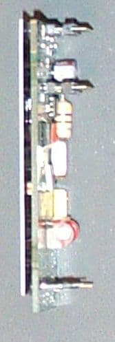
Click to zoom
Application Details
- Equipment Class
- DSS - Part 15 Spread Spectrum Transmitter
- Date of Grant
- May 14, 2001
- Application Purpose
- Original Equipment
- Date of Application
- Dec 05, 2000
- Equipment Note
- Direct Sequence Spread Spectrum Module
- Frequency Range
- 923.58000000 - 923.58000000
- Company
- Spot LLC
- Country
- United States
Documents & Files
Document Text
Text extracted from the exhibit documents filed with the FCC. Open a document above to read the original.
Users Manual
FCC ID: L2VAX630 SECTION 7 USER'S MANUAL FCC ID: L2VAX630 FCC ID: L2VAX630
Users Manual
Axonn Corporation AX630 Transmitter Users Manual RF Transmitter Installation Instructions The AX630 Transmitter is a member of our Spread Spectrum RF family of products. This transmitter should only be installed by qualified service personnel. The transmitter detects level, low battery or other data signals from the external binary inputs and broadcasts that data to the system's host receiver. MOUNTING LOCATION The AX630 Transmitter is a module as defined by the FCC and therefore must be mounted to another host device in order to function. NOTICE TO CUSTOMER Any Axonn customer incorporating the AX630 transmitter module into its own product must have an external notice affixed to its product. This notice must be placed in a conspicuous location and can use wording such as: “Contains FCC ID: L2VAX630” or “Contains Transmitter Module FCC ID: L2VAX630”. Any similar wording that expresses the same meaning may be used. INSTALLATION INSTRUCTIONS 1. Supply the transmitter with DC power by inserting a 3Volt battery into the battery holder on the customers host application circuit board. 2. The unit will come pre-programmed with Transmitter ID and Property Code. There will be no field programming of the unit. 3. When installing the AX630 you should avoid areas near screens, metal window frames, circuit breaker boxes, air conditioners and heaters if a suitable location for the unit may be found elsewhere. TESTING THE TRANSMITTER Following system installation, system testing is mandatory. This should be performed by locating the AX630 in its final location and powering up the unit. On initial power-up, the AX630 will send out RF messages every 4 seconds or more depending on programming. This will establish communications with the Host receiver and the information collected will then be used to judge system performance. FCC NOTICE The Model AX630 transmitter generates and uses radio frequency energy. If not installed and used in accordance with the manufacturer's instructions, it may cause interference to radio and television reception. The transmitter has been tested and found to comply with the specifications in Part 15 of FCC Rules for Spread Spectrum Intentional Radiators and FCC Part 15 Subpart C, Specifications. If this equipment causes interference to radio or television reception - which can be determined by turning the equipment on and off - the installer is encouraged to correct the interference by one or more of the following measures: 1) Reorient the antenna of the radio/television. 2) Connect the AC transformer to a different outlet so the control panel and radio/television are on different branch circuits. 3) Relocate the control panel with respect to the radio/television. If necessary, the installer should consult an experienced radio/television technician for additional suggestions, or send for the "Interference Handbook" prepared by the Federal Communications Commission. This booklet is available from the U.S. Government Printing Office, Washington, D.C., 20402, stock number 004-000-00450-7. CAUTION: Axonn Corporation does not support field changes or modifications to any of the Axonn Corporation RF equipment unless they are specifically covered in this manual. All adjustments must be made at the factory under the specific guidelines set forth in our manufacturing processes. Any modification to the equipment could void the user's authority to operate the equipment and render the equipment in violation of FCC Part 15, Subpart C, 15.247. This device complies with Part 15 of the FCC Rules. Operation is subject to the following two conditions: (1) this device may not cause harmful interference, and (2) this device must accept any interference received, including interference that may cause undesired operation. CAUTION: This device is required to comply with FCC RF exposure requirements for mobile transmitting devices. A separation of 20 cm (8 inches) or more must be maintained between the antenna and all persons during device operations to satisfy RF exposure compliance. LIMITED WARRANTY THERE ARE NOT WARRANTIES, EXPRESS OR IMPLIED, OF MERCHANTABILITY OR FITNESS FOR A PARTICULAR PURPOSE OR OTHERWISE, WHICH EXTEND BEYOND THE DESCRIPTION ON THE FACE HEREOF. In no case shall Seller be liable to anyone for any consequential or incidental damages for breach of this or any other warranty, express or implied, or upon any other basis of liability whatsoever, even if the loss or damage is caused by Seller's own negligence or fault.
Cover Letter(s)
L.L.C. 2021 Lakeshore Drive ∙ Suite 500 ∙ New Orleans, Louisiana 70122 ∙ (504) 282-8119 ∙ FAX (504) 304-2427 April 9, 2001 Federal Communicatio ns Commissio n Equipment Authorization Div ision 7435 Oakland Mills Road Columbia, MD 21046 Dear Sir or Madam: This letter is a follow-up to request that the attached filing (FCC ID L2VAX630) be submitted for modular approval. Prior discussion with the commission centered on the issue of shielding for a Part 15 modular application. Axonn has modified its design to include a shield to comply with FCC Public Notice DA 00-1407. The L2VAX630 has an attached shield that is similar in form and function to the shielding of OJM-TR-916-SC, which has receiv ed modular approval of the commission. Axonn L.L.C. appreciates the fact that the commission must maintain product integr ity w ithout giv ing one company a competitiv e adv antage ov er another company. In defense of Axonn’s modular application for the L2VAX630, the following is re-stated: 1. The dev ice incorporates the following harmonic suppression techniques: Surface mount and co-planar technology is used throughout the design, minimizing stray RF fields that launch electromagnetic waves. Nov el filter technology that prov ides guaranteed suppression of transmitter spurious products by design. Each circuit is statistically modeled using computer aided design techniques for 6-sigma repeatability with the tolerances of the low-cost components used. Innov ativ e signal generation techniques which utilize the power of Fourier analysis to suppress even-order harmonics in the generation of the transmitted signal. A self-contained, printed-circuit antenna is utilized to guarantee a stable output match to the final amplifier. The printed antenna dispenses with the variability of externally mounted alternativ es that could prov ide indeterminate terminations to the transmitter output. Indeterminate terminations cause reflections to the output circuitry of other transmitters, resulting in increased spurious products. 2. All data inputs are buffered. 3. The dev ice has its own power supply regulation. 4. The dev ice is a complete transmitter module, with its own reference oscillator and printed antenna. All connectors are for power supply data inputs. 5. The dev ice was submitted as a stand-alone unit for testing. The conducted emissions requirements do not apply as this will be a battery-powered unit. Other points of discussion concerning modular transmitter approvals are covered in other portions of this application. Axonn L.L.C appreciates the approach that the commission has taken in regards to Part 15 modular approval, in that the modular approval guidelines allow rapid deployment of wireless technology w hil e maintain ing product integr ity. Best Regards, David Alley Axonn L.L.C.
Cover Letter(s)
L.L.C. 2021 Lakeshore Drive· Suite 500 · New Orleans, Louisiana 70122 · (504) 282-8119 · FAX (504) 304-2427 May 14, 2001 Federal Communications Commission Authorization and Evaluation Division Laboratory Division 7435 Oakland Mills Road Columbia, MD 21046 Dear Sir or Madam: In reference to the application under FCC ID L2VAX630 for the Axonn Corporation AX630 Transmitter, 0644-0100, we hereby request that the following materials submitted with the application be withheld from public disclosure: Exhibit I Block Diagrams Exhibit II Schematics Each Exhibit covered by the instant request is marked on the cover page to each. In support of its request for confidentiality, the following is stated. The subject device employs the emerging technology, spread spectrum. Research and development of this technology for commercial applications by the public is being explored by a number of entities and companies. The developer of the technology used to produce the instant device, Axonn Corporation, has emerged as one of the industry leaders and has gained a competitive edge over its competition by employing creative and functional circuit designs and production methods. This competitive position has been carefully cultivated and promoted to the benefit of Axonn and its licensees of its technology. Axonn Corporation foresees that this Transmitter shall only be purchased and installed by professionals. We do not currently foresee ourselves making this product available over-the-counter to the average consumer. Axonn Corporation has obtained licenses and continues to file for patents to protect each new generation of its spread spectrum technology. However, as the commission is aware, the time period for grant of such protection does not accommodate the need to bring devices to the marketplace. Accordingly, Axonn Corporation desires to bring its devices to the marketplace without creating undue risk of duplication of technical, proprietary design. Best Regards, David Alley Axonn L.L.C.
ID Label/Location Info
FCC ID: L2VAX630 FCC ID will be part of boards silkscreen as shown below
Internal Photos
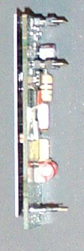
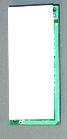
FCC ID: L2VAX630 SECTION 5 PHOTOGRAPHS FCC ID: L2VAX630 PHOTOS OF THE TESTED EUT The following photos are attached: Photo 1.Top View Showing EUT & Test Board Photo 2. Top View of Test Board with EUT Removed Photo 3.EUT, Bottom View of Test Board Photo 4.EUT, Top View Photo 5.EUT, Bottom View FCC ID: L2VAX630 Photo 1.Top View Showing EUT & Test Board FCC ID: L2VAX630 Photo 2. Top View of Test Board with EUT Removed FCC ID: L2VAX630 Photo 3.EUT, Bottom View of Test Board FCC ID: L2VAX630 Photo 4.EUT, Top View FCC ID: L2VAX630 Photo 5.EUT, Bottom View
RF Exposure Info
FCC ID: L2VAX630 SECTION 6 RF EXPOSURE INFORMATION FCC ID: L2VAX630 6.1 RF Safety Requirements to 2.1091 for Mobile Transmitters The EUT is being submitted for modular approval. However, due to the design of the transmitter and low duty cycle the manufacturer only expects the EUT to be used in mobile environment. The unit under evaluation has an integral antenna of –1.0 dBi gain with a measured output power output of 0.059 Watts at the antenna terminals. Taking into consideration the gain of the antenna, the corrected EIRP is 46.9 mW. The MPE calculations are shown as follows: The limits for this unit (uncontrolled exposure) are 1.0 mW/cm 2 . Taking the RF Density Field Equation: S = EIRP (mW)/(4πR 2 ) and solving for Distance R R = SQRT(EIRP (mW)/(S4π)) Plugging in data yields R (cm) = SQRT (46.9 (mw)/(1.0 (mW/cm 2 )*4*π) ) = 3.7 cm The RF Density equation shows that the minimum separation distance to be 3.7 cm. Since the EUT is considered by the manufacture to be a mobile unit, which by definition specifies that the antenna distance is greater than 20 cm, the manual therefore incorporates a caution statement that states that the unit should only be used when a separation of 20 cm is maintained between the antenna and users. This ensures compliance with the MPE requirements.
RF Exposure Info
FCC ID: L2VAX630 SECTION 7 USER'S MANUAL FCC ID: L2VAX630 FCC ID: L2VAX630
Test Report
Axonn Corporation FCC Part 15, Certification Application AX-630 Transmitter UST Project: 00-0386 December 6, 2000 MEASUREMENT/TECHNICAL REPORT COMPANY NAME:Axonn Corporation MODEL:AX-630 Transmitter FCC ID:L2VAX630 DATE:December 6, 2000 This report concerns (check one): Original grant X Class II change_____ Equipment type: Direct Sequence Spread Spectrum (Modular) Deferred grant requested per 47 CFR 0.457(d)(1)(ii)? yes_____ No X If yes, defer until:_________________ date N.A. agrees to notify the Commission by N.A. date of the intended date of announcement of the product so that the grant can be issued on that date. Report prepared by: United States Technologies, Inc. 3505 Francis Circle Alpharetta, GA 30004 Phone Number: (770) 740-0717 Fax Number: (770) 740-1508 FCC ID: L2VAX630 TABLE OF CONTENTS LETTER OF CONFIDENTIALITY SECTION 1 GENERAL INFORMATION 1.1Product Description 1.2Related Submittal(s) SECTION 2 TESTS AND MEASUREMENTS 2.1Configuration of Tested EUT 2.2Test Facility 2.3Test Equipment 2.4Modifications 2.5Test Procedure and Results 2.6Antenna Description 2.7Peak Power (Antenna Conducted at Antenna Terminal) 2.8Antenna Conducted Spurious Emissions 2.9Peak Radiated Spurious Emissions 2.10Average Radiated Spurious Emissions 2.11Minimum 6 dB Bandwidth 2.12Power Spectral Density 2.13Processing Gain 2.14Power Line Conducted Emissions for Transmitter 2.15Radiated Emissions for Digital Device & Receiver (if Applicable) 2.16Power Line Conducted for Digital Device & Receiver (if Applicable) SECTION 3 LABELING INFORMATION SECTION 4 BLOCK DIAGRAM(S)/ SCHEMATIC(S) SECTION 5 PHOTOGRAPHS SECTION 6 RF EXPOSURE INFORMATION SECTION 7 USER'S MANUAL FCC ID: L2VAX630 LIST OF FIGURES AND TABLES 1)Test Configuration 2) Photograph(s) for Spurious and Digital Device Emissions 3) Peak Power Output 4) Antenna Conducted Spurious Emissions 5) Peak Radiated Spurious Emissions 6) Average Radiated Spurious Emissions 7) Minimum 6 dB Bandwidth 8) Power Spectral Density TABLES 1)EUT and Peripherals 2) Test Instruments 3) Peak Power Output 4) Peak Radiated Spurious Emissions 5) Average Radiated Spurious Emissions 6) Power Spectral Density 7) Conducted Emissions Data (Transmitter) 8) Radiated Emissions Data (Digital Device) 9) Conducted Emissions Data (Digital Device) FCC ID: L2VAX630 SECTION 1 GENERAL INFORMATION FCC ID: L2VAX630 GENERAL INFORMATION 1.1Product Description The Equipment Under Test (EUT) is the Axonn Corporation’s, Model AX-630 Transmitter. The EUT transmits signals of binary switch inputs to a receiver. The EUT utilizes direct sequence spread spectrum technology for communication at 923.58 MHz at approximately 50 mW output power. The EUT will typically derive its power from an internally mounted 3 VDC battery (external to module). This application is being submitted in order to approve the EUT as a stand-alone module. Please refer to the following letter from Axonn Corporation. FCC ID: L2VAX630 FCC ID: L2VAX630 1.2Related Submittal(s)/Grant(s) The EUT will be used with part of a system to send/receive data. The transmitter presented in this report will be used with previously approved receivers (FCC ID: L2V0536ASR2). The EUT is subject to the following authorizations: a)Certification as a transmitter The information contained in this report is presented for the certification authorization for the EUT. FCC ID: L2VAX630 SECTION 2 TESTS AND MEASUREMENTS FCC ID: L2VAX630 TEST AND MEASUREMENTS 2.1 Configuration of Tested System The sample was tested per ANSI C63.4, Methods of Measurement from Low-Voltage Electrical and Electronic Equipment in the Range of 9 kHz to 40 GHz (1992). Conducted and radiated emissions data were taken with the test receiver or spectrum analyzer's resolution bandwidth adjusted to 9 kHz and 120 kHz, respectively. All measurements are peak unless stated otherwise. The video filter associated with the spectrum analyzer was off throughout the evaluation process. Interconnecting cables were manipulated as necessary to maximize emissions. Interconnecting cables were manipulated as necessary to maximize emissions. A block diagram of the tested system is shown in Figure 1. Test configuration photographs for spurious and fundamental emissions are shown in Figure 2. The sample used for testing was received by U.S. Technologies on August 23, 2000 in good condition. 2.2 Test Facility Testing was performed at US Tech's measurement facility at 3505 Francis Circle, Alpharetta, GA. This site has been fully described and submitted to the FCC, and accepted in their letter marked 31040/SIT. Additionally this site has also been fully described and submitted to Industry Canada (IC), and has been approved under file number IC2982. 2.3 Test Equipment Table 2 describes test equipment used to evaluate this product. 2.4 Modifications No modifications were made by US Tech, to bring the EUT into compliance with FCC Part 15 limits for the transmitter portion of the EUT. FCC ID: L2VAX630 FIGURE 1 TEST CONFIGURATION (All tests except for conducted emissions) Axonn Corporation does not anticipate any applications for use in products other than battery powered applications. Therefore all tests except conducted emissions were performed under battery power as shown above. However, to ensure that the EUT has been tested for all future applications, an additional conducted test was performed by removing the battery from the test board above and attaching an AC adapter as shown below. (Conducted emissions only) EUT with Test Board (with battery) EUT with Test Board (w/o battery) AC Adapter 6' u FCC ID: L2VAX630 Test Date:September 22-23, 2000 UST Project:00-0386 Customer:Axonn Corporation Model:AX-630 Transmitter FIGURE 2a Photograph(s) for Spurious Emissions (Front) FCC ID: L2VAX630 Test Date:September 22-23, 2000 UST Project:00-0386 Customer:Axonn Corporation Model:AX-630 Transmitter FIGURE 2b Photograph(s) for Spurious Emissions (Back) FCC ID: L2VAX630 Test Date:September 22-23, 2000 UST Project:00-0386 Custome…
Text truncated - open the document above for the full version.
Test Report
LLC 2021 Lakeshore Drive · Suite 500 · New Orleans, Louisiana 70122 · (504) 282-8119 · FAX (504) 304 2427 April 19, 2001 Tim Johnson U. S. Technologies 3505 Francis Circle Alpharetta, GA 30004 (770) 740-0717 Dear Tim, This letter serves to confirm several of the operating parameters of the AX630 transmitter. The device is a spread spectrum transmitter that operates at a single frequency, namely 923.58 MHz. The device has an on-air data rate of 19.39 kb/s and utilizes ASK data modulation. The AX630 is a direct sequence spread spectrum transmitter that uses a BPSK spreading modulation with 63 spreading code ‘chips’ per data bit. A spread spectrum receiver that receives transmissions from the AX630 has FCC ID L2V0536ASR2. The theoretical process gain of the transmitter is defined by the spread occupied bandwidth (2*chipping frequency) divided by the narrowest filter in the receiver: 10 log (2.44MHz / 110kHz) = 13.46 dB Best regards, David Alley Axonn LLC
Contact Information
Applicant
Matthew Kapral(Senior Quality Engineer)
Technical Contact
United States TechnologiesTimothy R Johnson
[email protected]770-740-0717
3505 Francis Circle · Alpharetta, Georgia · United States
Non-Technical Contact
United States TechnologiesTimothy R Johnson
[email protected]770-740-0717
Test Firm
US TechSandy McEnery
Technical Specifications
| # | Rule Parts | Frequency Range | Power Output |
|---|---|---|---|
| 1 | 15C | 923.58 MHz - 923.58 MHz | 59.00 mW |
Other Applications from Spot LLC
L2V-RX200M
Aug 14, 2024Simplex Satellite Transmitter Module with Bluetooth designed to be embedded in a customer end product
Equipment Class
TNB - Licensed Non-Broadcast Station Transmitter
L2V-TRACE2
Jan 10, 2023Satellite Asset Tracker
Equipment Class
TNB - Licensed Non-Broadcast Station Transmitter
L2V-ST150M
Oct 05, 2022Simplex Satellite Transmitter Module with Bluetooth
Equipment Class
DTS - Digital Transmission System
L2V-ST100
Jul 14, 2020Simplex Satellite Transmitter Module with Bluetooth
Equipment Class
TNB - Licensed Non-Broadcast Station Transmitter
L2V-STGR
Aug 09, 2015Globalstar STINGR
Equipment Class
TNB - Licensed Non-Broadcast Station Transmitter