L2VAXC550INTAXC550 (Internal) Transceiver
Spot LLC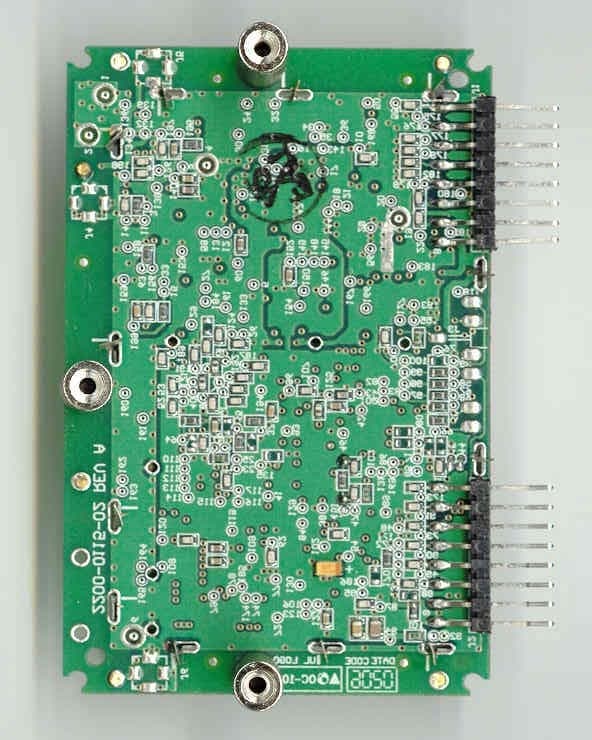
Click to zoom
Application Details
- Equipment Class
- DTS - Digital Transmission System
- Date of Grant
- Nov 25, 2002
- Application Purpose
- Original Equipment
- Date of Application
- Nov 25, 2002
- Equipment Note
- AXC550 (Internal) Transceiver
- Frequency Range
- 905.58000000 - 926.58000000
- Company
- Spot LLC
- Country
- United States
Documents & Files
Document Text
Text extracted from the exhibit documents filed with the FCC. Open a document above to read the original.
Users Manual
FCC ID: L2VAXC550INT FCC ID: L2VAXC550INT
Cover Letter(s)
FCC ID: L2VAXC550INT
Cover Letter(s)
FCC ID: L2VAXC550INT
Cover Letter(s)
FCC ID: L2VAXC550INT FCC ID: L2VAXC550INT
Cover Letter(s)
American Telecommunications Certification Body Inc. 6731 Whittier Ave, McLean, VA 22101 October 18, 2002 RE: FCC ID: L2VAXC550INT Attention: Timothy R. Johnson I have a few comments on this Application. 1 Please provide information on what the label is made of and how it is permanently affixed to the device. 2 Please note that the gain specified in the allowable formula from 97-114 defines that gain as, “G is the numeric gain of the transmitting antenna over an isotropic radiator.” This means that the resultant power is EIRP not ERP. Thus, you must use the formula as provided and cannot reduce the level by the dipole gain. The device appears to fail since the properly calculated value appears to be 9.87dBm. Please retest the device to show compliance the required test method and rules stipulated by the FCC. Alternately please explain and justify why you used ERP values. Such justification would require evidence from the FCC that you are allowed to reduce EIRP to ERP or to use a formula using gain referenced to a dipole instead of an isotropic as stipulated in the acceptable test procedure. Dennis Ward mailto:[email protected] The items indicated above must be submitted before processing can continue on the above referenced application. Failure to provide the requested information may result in application termination. Correspondence should be considered part of the permanent submission and may be viewed from the Internet after a Grant of Equipment Authorization is issued. Please do not respond to this correspondence using the email reply button. In order for your response to be processed expeditiously, you must submit your documents through the AmericanTCB.com website. Also, please note that partial responses increase processing time and should not be submitted. Any questions about the content of this correspondence should be directed to the sender.
Cover Letter(s)
Response for Request for information (request sent 10/18/02) for Re: FCC ID: L2VAXC550INT Applicant: Axonn L.L.C. Correspondence Reference Number: N/A 731 Confirmation Number: N/A 1) Please provide information on what the label is made of and how it is permanently affixed to the device. According to the manufacturer, the label is made of paper but uses a permanent adhesive such that the label would have to be destroyed if an attempt was made to remove it. Additionally the manufacturer has tested the labels through salt, fog, and UV and has not had any problems with adhesion. Acceptability by the FCC of this label has been provided in a separate email. 2) Please note that the gain specified in the allowable formula from 97-114 defines that gain as, “G is the numeric gain of the transmitting antenna over an isotropic radiator.” This means that the resultant power is EIRP not ERP. Thus, you must use the formula as provided and cannot reduce the level by the dipole gain. The device appears to fail since the properly calculated value appears to be 9.87dBm. Please retest the device to show compliance the required test method and rules stipulated by the FCC. Alternately please explain and justify why you used ERP values. Such justification would require evidence from the FCC that you are allowed to reduce EIRP to ERP or to use a formula using gain referenced to a dipole instead of an isotropic as stipulated in the acceptable test procedure. You are correct that there is an error in this calculation. From discussing this issue with the manufacturer, they believe that the gain of the TX antenna may be more than the 0 dBi originally specified at very particular positions or angles. The gain provided is based on early investigations that they had performed but which may not have carefully evaluated all “hot” spots. Since the are not currently ready to perform another detailed analysis of this antenna, the manufacture has specified how a direct measurement may be performed. This measurement was made in order to show the EUT is in compliance with the power spectral density requirements. The test report has been updated for this test.
External Photos
FCC ID: L2VAXC550INT Photo 1.EUT, Top View TX Antenna RX Antennas FCC ID: L2VAXC550INT Photo 3.EUT, Bottom View
ID Label/Location Info
FCC ID: L2VAXC550INT Label FCC ID: L2VAXC550INT
Internal Photos
FCC ID: L2VAXC550INT Photo 1.EUT, Top View TX Antenna RX Antennas FCC ID: L2VAXC550INT Photo 2.EUT, Top View - Shield Removed FCC ID: L2VAXC550INT Photo 3.EUT, Bottom View
Operational Description
FCC ID: L2VAXC550INT GENERAL INFORMATION 1.1Product Description The Equipment Under Test (EUT) is the Axonn L.L.C.’s, Model AXC550 (Internal), Rev B Transmitter. The EUT utilizes direct sequence spread spectrum technology for communication on the following channels: 905.58, 908.58, 911.58, 914.58, 917.58, 920.58, 923.58, and 926.58 MHz. The transmitter modulation incorporates BPSK modulation for generating a direct-sequence, spread spectrum carrier. The data modulation for the device utilizes either OOK or BPSK data modulation techniques as selectable by the user application. The EUT it identical to a previously approved version (which was modularly approved under FCC ID: L2VAX550) with the exception that one of the regulators has been removed from the transmitter board and is to be implemented by the outside host devices. This application is being submitted in order to approve the EUT as a stand-alone limited modular approval (limited for use within Axonn L.L.C. products only) since Axonn will maintain control of the final products and ensure that the transmitter module is fully supplied with the proper external regulated voltage. Please refer to the following letter from Axonn L.L.C.
RF Exposure Info
FCC ID: L2VAXC550INT 6.1 RF Safety Requirements to 2.1091 for Mobile Transmitters The EUT is being submitted for modular approval. However, due to the design of the transmitter and low duty cycle the manufacturer only expects the EUT to be used in mobile environment. The unit under evaluation has an integral antenna of +0 dBi gain with a measured output power output of 0.165 Watts at the antenna terminals. Taking into consideration the gain of the antenna, the corrected EIRP is 165 mW. The MPE calculations are shown as follows: The limits for this unit (uncontrolled exposure) are 0.6 mW/cm 2 (900 MHz/1500). Taking the RF Density Field Equation: S = EIRP (mW)/(4πR 2 ) and solving for Distance R R = SQRT(EIRP (mW)/(S4π)) Plugging in data yields R (cm) = SQRT (165 (mw)/(0.6 (mW/cm 2 )*4*π) ) = 4.7 cm The RF Density equation shows that the minimum separation distance to be 4.7 cm. Since the EUT is considered by the manufacture to be a mobile unit, which by definition specifies that the antenna distance is greater than 20 cm, the manual therefore incorporates a caution statement that states that the unit should only be used when a separation of 20 cm is maintained between the antenna and users. This ensures compliance with the MPE requirements.
Test Report
Axonn L.L.C. FCC Part 15, Certification Application AXC550 (Internal), Rev B Transmitter UST Project: 02-0266 September 12, 2002 MEASUREMENT/TECHNICAL REPORT COMPANY NAME:Axonn L.L.C. MODEL:AXC550 (Internal), Rev B Transmitter FCC ID:L2VAXC550INT DATE:September 12, 2002 This report concerns (check one): Original grant X Class II change_____ Equipment type: Direct Sequence Spread Spectrum (Modular) Deferred grant requested per 47 CFR 0.457(d)(1)(ii)? yes_____ No X If yes, defer until:_________________ date N.A. agrees to notify the Commission by N.A. date of the intended date of announcement of the product so that the grant can be issued on that date. Report prepared by: United States Technologies, Inc. 3505 Francis Circle Alpharetta, GA 30004 Phone Number: (770) 740-0717 Fax Number: (770) 740-1508 FCC ID: L2VAXC550INT TABLE OF CONTENTS AGENCY AGREEMENT LETTER OF CONFIDENTIALITY SECTION 1 GENERAL INFORMATION 1.1 Product Description 1.2 Related Submittal(s) SECTION 2 TESTS AND MEASUREMENTS 2.1 Configuration of Tested EUT 2.2 Test Facility 2.3 Test Equipment 2.4 Modifications 2.5 Test Procedure and Results 2.6 Antenna Description 2.7 Peak Power (Antenna Conducted at Antenna Terminal) 2.8 Antenna Conducted Spurious Emissions 2.9 Peak Radiated Spurious Emissions 2.10 Average Radiated Spurious Emissions 2.11 Minimum 6 dB Bandwidth 2.12 Power Spectral Density 2.13 Power Line Conducted Emissions for Transmitter 2.14 Radiated Emissions for Digital Device & Receiver (if Applicable) 2.15 Power Line Conducted for Digital Device & Receiver SECTION 3 LABELING INFORMATION SECTION 4 BLOCK DIAGRAM(S)/ SCHEMATIC(S) SECTION 5 PHOTOGRAPHS SECTION 6 RF EXPOSURE INFORMATION SECTION 7 USER'S MANUAL FCC ID: L2VAXC550INT LIST OF FIGURES AND TABLES 1)Test Configuration 2) Photograph(s) for Spurious and Digital Device Emissions 3) Peak Power Output 4) Antenna Conducted Spurious Emissions 5) Peak Radiated Spurious Emissions 6) Average Radiated Spurious Emissions 7) Minimum 6 dB Bandwidth 8) Power Spectral Density TABLES 1)EUT and Peripherals 2) Test Instruments 3) Peak Power Output 4) Peak Radiated Spurious Emissions 5) Average Radiated Spurious Emissions 6) Power Spectral Density 7) Conducted Emissions Data (Transmitter) 8) Radiated Emissions Data (Digital Device) 9) Conducted Emissions Data (Digital Device) FCC ID: L2VAXC550INT SECTION 1 GENERAL INFORMATION FCC ID: L2VAXC550INT GENERAL INFORMATION 1.1Product Description The Equipment Under Test (EUT) is the Axonn L.L.C.’s, Model AXC550 (Internal), Rev B Transmitter. The EUT utilizes direct sequence spread spectrum technology for communication on the following channels: 905.58, 908.58, 911.58, 914.58, 917.58, 920.58, 923.58, and 926.58 MHz. The transmitter modulation incorporates BPSK modulation for generating a direct-sequence, spread spectrum carrier. The data modulation for the device utilizes either OOK or BPSK data modulation techniques as selectable by the user application. The EUT it identical to a previously approved version (which was modularly approved under FCC ID: L2VAX550) with the exception that one of the regulators has been removed from the transmitter board and is to be implemented by the outside host devices. This application is being submitted in order to approve the EUT as a stand-alone limited modular approval (limited for use within Axonn L.L.C. products only) since Axonn will maintain control of the final products and ensure that the transmitter module is fully supplied with the proper external regulated voltage. Please refer to the following letter from Axonn L.L.C. FCC ID: L2VAXC550INT FCC ID: L2VAXC550INT FCC ID: L2VAXC550INT 1.2Related Submittal(s)/Grant(s) The EUT will be used with part of a system to send/receive data. The transmitter presented in this report will be used with similar transceivers or previously approved receivers. The EUT is subject to the following authorizations: a) Certification as a transmitter (limited modular approval) The information contained in this report is presented for the certification authorization for the EUT. FCC ID: L2VAXC550INT SECTION 2 TESTS AND MEASUREMENTS FCC ID: L2VAXC550INT TEST AND MEASUREMENTS 2.1 Configuration of Tested System The sample was tested per ANSI C63.4, Methods of Measurement from Low-Voltage Electrical and Electronic Equipment in the Range of 9 kHz to 40 GHz (1992). Conducted and radiated emissions data were taken with the test receiver or spectrum analyzer's resolution bandwidth adjusted to 9 kHz and 120 kHz, respectively. All measurements are peak unless stated otherwise. The video filter associated with the spectrum analyzer was off throughout the evaluation process. Interconnecting cables were manipulated as necessary to maximize emissions. Interconnecting cables were manipulated as necessary to maximize emissions. A block diagram of the tested system is shown in Figure 1. Test configuration photographs for spurious and fundamental emissions are shown in Figure 2. The sample used for testing was received by U.S. Technologies on July 30, 2002 in good condition. 2.2 Test Facility Testing was performed at US Tech's measurement facility at 3505 Francis Circle, Alpharetta, GA. This site has been fully described and submitted to the FCC, and accepted in their letter marked 31040/SIT. Additionally this site has also been fully described and submitted to Industry Canada (IC), and has been approved under file number IC2982. 2.3 Test Equipment Table 2 describes test equipment used to evaluate this product. 2.4 Modifications No modifications were made by US Tech, to bring the EUT into compliance with FCC Part 15 limits for the transmitter portion of the EUT. FCC ID: L2VAXC550INT FIGURE 1 TEST CONFIGURATION Transceiver (EUT) Interface Box AC Adapter 6' u To Laptop for Control Commands as Necessary 6' s 120 VAC, 60 Hz Direct Plug In 3' u FCC ID: L2VAXC550INT Test Date:July 30 – July 31, 2002 UST Project:02-0266 Customer:Axonn L.L.C. Model:AXC550 (Internal), Rev B Transmitter FIGURE 2a Ph…
Text truncated - open the document above for the full version.
Test Setup Photos
FCC ID: L2VAXC550INT Test Date:July 30 – July 31, 2002 UST Project:02-0266 Customer:Axonn L.L.C. Model:AXC550 (Internal), Rev B Transmitter FIGURE 2a Photograph(s) for Spurious Emissions (Front) EUT Interface Box FCC ID: L2VAXC550INT Test Date:July 30 – July 31, 2002 UST Project:02-0266 Customer:Axonn L.L.C. Model:AXC550 (Internal), Rev B Transmitter FIGURE 2b Photograph(s) for Spurious Emissions (Back) FCC ID: L2VAXC550INT Test Date:July 30 – July 31, 2002 UST Project:02-0266 Customer:Axonn L.L.C. Model:AXC550 (Internal), Rev B Transmitter FIGURE 2c Photograph(s) for Digital Device/Receiver Emissions (Front) FCC ID: L2VAXC550INT Test Date:July 30 – July 31, 2002 UST Project:02-0266 Customer:Axonn L.L.C. Model:AXC550 (Internal), Rev B Transmitter FIGURE 2d Photograph(s) for Digital Device/Receiver Emissions (Back) FCC ID: L2VAXC550INT Test Date:July 30 – July 31, 2002 UST Project:02-0266 Customer:Axonn L.L.C. Model:AXC550 (Internal), Rev B Transmitter FIGURE 2e Photograph(s) for Conducted Emissions Transmitter FCC ID: L2VAXC550INT Test Date:July 30 – July 31, 2002 UST Project:02-0266 Customer:Axonn L.L.C. Model:AXC550 (Internal), Rev B Transmitter FIGURE 2f Photograph(s) for Conducted Emissions Receiver
Contact Information
Applicant
Matthew Kapral(Senior Quality Engineer)
Technical Contact
U.S. TechnologiesTimothy R Johnson
[email protected]770-740-0717
3505 Francis Circle · Alpharetta, Georgia · United States
Non-Technical Contact
U.S. TechnologiesTimothy R Johnson
[email protected]770-740-0717
Test Firm
US TechSandy McEnery
Technical Specifications
| # | Rule Parts | Frequency Range | Power Output |
|---|---|---|---|
| 1 | 15C | 905.58 MHz - 926.58 MHz | 165.00 mW |
Other Applications from Spot LLC
L2V-RX200M
Aug 14, 2024Simplex Satellite Transmitter Module with Bluetooth designed to be embedded in a customer end product
Equipment Class
TNB - Licensed Non-Broadcast Station Transmitter
L2V-TRACE2
Jan 10, 2023Satellite Asset Tracker
Equipment Class
TNB - Licensed Non-Broadcast Station Transmitter
L2V-ST150M
Oct 05, 2022Simplex Satellite Transmitter Module with Bluetooth
Equipment Class
DTS - Digital Transmission System
L2V-ST100
Jul 14, 2020Simplex Satellite Transmitter Module with Bluetooth
Equipment Class
TNB - Licensed Non-Broadcast Station Transmitter
L2V-STGR
Aug 09, 2015Globalstar STINGR
Equipment Class
TNB - Licensed Non-Broadcast Station Transmitter