L8G8800002WLAN USB Adapter
Lantech Advance Corporation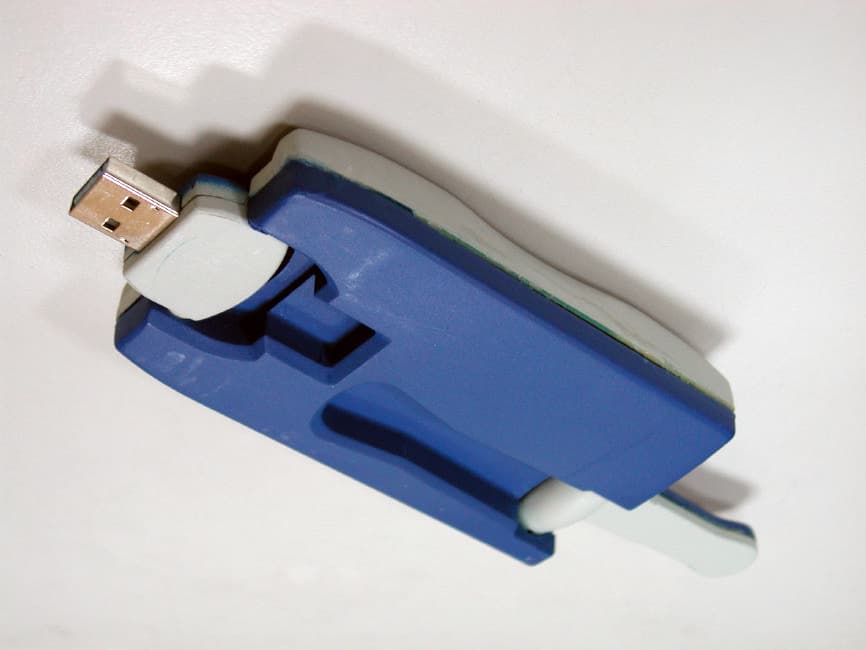
Click to zoom
Application Details
- Equipment Class
- DSS - Part 15 Spread Spectrum Transmitter
- Date of Grant
- Jul 26, 2002
- Application Purpose
- Original Equipment
- Date of Application
- Jul 26, 2002
- Equipment Note
- WLAN USB Adapter
- Frequency Range
- 2412.00000000 - 2462.00000000
- Company
- Lantech Advance Corporation
- Country
- Taiwan
Documents & Files
Document Text
Text extracted from the exhibit documents filed with the FCC. Open a document above to read the original.
Users Manual
W W L L A A N N U U S S B B A A d d a a p p t t e e r r Regulatory notes and statements Wireless LAN, Health and Authorization for use Radio frequency electromagnetic energy is emitted from Wireless LAN devices. The energy levels of these emissions however are far much less than the electromagnetic energy emissions from wireless devices like for example mobile phones. Wireless LAN devices are safe for use frequency safety standards and recommendations. The use of Wireless LAN devices may be restricted in some situations or environments for example: · On board of airplanes, or · In an explosive environment, or · In case the interference risk to other devices or services is perceived or identified as harmful In case the policy regarding the use of Wireless LAN devices in specific organizations or environments (e.g. airports, hospitals, chemical/oil/gas industrial plants, private buildings etc.) is not clear, please ask for authorization to use these devices prior to operating the equipment. Regulatory Information/disclaimers Installation and use of this Wireless LAN device must be in strict accordance with the instructions included in the user documentation provided with the product. Any changes or modifications made to this device that are not expressly approved by the manufacturer may void the user’s authority to operate the equipment. The Manufacturer is not responsible for any radio or television interference caused by unauthorized modification of this device, of the substitution or attachment. Manufacturer and its authorized resellers or distributors will assume no liability for any damage or violation of government regulations arising from failing to comply with these guidelines. USA-FCC (Federal Communications Commission) statement This device complies with Part 15 of FCC Rules. Operation is subject to the following two conditions: 1. This device may not cause interference, and 2. This device must accept any interference, including interference that may cause undesired operation of this device. FCC Radio Frequency Exposure statement This Wireless LAN radio device has been evaluated under FCC Bulletin OET 64C and found compliant to the requirements as set forth in CFR 47 Sections 2.1091, 2.1093, and 15.247 (b) (4) addressing RF Exposure from radio frequency devices. The radiated output power of this Wireless LAN device is far below the FCC radio frequency exposure limits. Nevertheless, this device shall be used in such a manner that the potential for human contact during normal operation is minimized. When nearby persons has to be kept to ensure RF exposure compliance. In order to comply with RF exposure limits established in the ANSI C95.1 standards, the distance between the antennas and the user should not be less than 20 cm. FCC Interference Statement This equipment has been tested and found to comply with the limits for a Class B digital device, pursuant to Part 15 of the FCC Rules. These limits are designed to provide reasonable protection against harmful interference in a residential installation. This equipment generates, uses, and can radiate radio frequency energy. If not installed and used in accordance with the instructions, it may cause harmful interference to radio communications. However, there is no guarantee that interference will not occur in a particular installation. If this equipment does cause harmful interference to radio or television reception, which can be determined by turning the equipment off and on, the user is encouraged to try and correct the interference by one or more of the following measures: 1. Reorient or relocate the receiving antenna. 2. Increase the distance between the equipment and the receiver. 3. Connect the equipment to an outlet on a circuit different from that to which the receiver is connected. 4. Consult the dealer or an experienced radio/TV technician for help. Export restrictions This product or software contains encryption code which may not be exported or transferred from the US of Canada without an approved US Department of Commerce export license. Safety Statements Federal Communications Commission Statement This device complies with FCC Rules Part 15. Operation is subject to the following two conditions: · This device may not cause harmful interference, and · This device must accept any interference received, including interference that may cause undesired operation. SAFETY INFORMATION Your device contains a low power transmitter. When device is transmitted it sends out radio frequency (RF) signal. CAUTION: To maintain compliance with FCC’s RF exposure guidelines, this equipment should be installed and operated with minimum distance 20cm between the radiator and your body. Use on the supplied antenna. Unauthorized antenna, modification, or attachments could damage the transmitter and may violate FCC regulations. Table of Contents 1. Introduction..................................................................................... 1 1.1 Package Contents ........................................................................ 2 1.2 Advantages for Using Wireless Network ........................................... 2 2. Step by step Installation Guide............................................... ............ 3 2.1 Install WLAN USB Adapter Utillity & Driver for Windows98, ME, and 2000........................................................................................ 3 2.2 Wireless LAN Monitor Utillity ....................................................... 5 2.2.1 Setting ........................................................ ..................... .. 6 2.2.2 Statistics .......................................................................... ... 7 2.2.3 Site Survey ............................................................................ 8 2.2.4 Encryption ........................................................... ................. 8 2.2.5 Advanced ..........................................................................…
Text truncated - open the document above for the full version.
Cover Letter(s)
American Telecommunications Certification Body Inc. 6731 Whittier Ave, McLean, VA 22101 July 9, 2002 RE: FCC ID: L8G8800002 Attention: Eric Wong I have a few comments on this Application. 1 The following documents can not be uploaded to the FCC because they contain Asian fonts; The Operational Description, the Parts List (BOM), the RF exposure, the Test Report and the User’s Manual. The FCC copy of adobe acrobat does not have the capability of reading these fonts. Please provide these documents without Asian fonts. xx 2 Section II of the report states the device is compliant to the antenna rules of 15.203 because it contains only an integral antenna and no other antenna can be used with the device. However the schematics appear to show a printed circuit board antenna (integral) and two selectable external antenna jack connections. In fact, J3 appears to be able to be selected at the same time as the printed circuit antenna. This means that there is a possibility for them to in collocation. This is not allowable under current FCC rules. Also, there appears to be another external antenna connection in J2. Please provide evidence that the statement in the report is accurate. This includes providing schematics that show how these other 2 external capable antenna connections are to be eliminated. This also includes evidence showing how the manufacturer will prevent both the circuit board antenna and the antenna connection of J3 from simultaneous selection and operation. xx 3 The device and the label location appear to be sufficiently large to accommodate the FCC ID number and the 2-condition statement per 15.19. Please provide a label that meets the requirements of 15.19 and 2.925. xx 4 In the RF exposure calculations you inadvertently used the dBm rather than the mW level. You also used a gain of isotropic (1) yet the antenna is said to be a dipole. Please correct the RF exposure statement to reflect the actual power measure at the antenna terminal and the actual gain of the dipole antenna used. xx 5 In the chart on page 40 of the report you state a level for Power Spectral Density in dBuV, however, the SA picture on page 41 is correct using dBm. Please note that PPSD is dBm. Please correct the chart to reflect the proper unit of measurement. xx Dennis Ward mailto:[email protected] The items indicated above must be submitted before processing can continue on the above referenced application. Failure to provide the requested information may result in application termination. Correspondence should be considered part of the permanent submission and may be viewed from the Internet after a Grant of Equipment Authorization is issued. Please do not respond to this correspondence using the email reply button. In order for your response to be processed expeditiously, you must submit your documents through the AmericanTCB.com website. Also, please note that partial responses increase processing time and should not be submitted. Any questions about the content of this correspondence should be directed to the sender.
Cover Letter(s)
Training Research Co., Ltd. No. 2, Lane 194, Huan-Ho St., Hsi-Chih, Taipei Hsien 221, Taiwan, R.O.C. TEL: 886-2-26935155 FAX: 886-2-26934440 TRCSince1985 ® June 22, 2002 RE: LANTECH Advance Corporation FCC ID: L8G8800002 Dear Dennis: After the review of your comments, we have made some response upon your advice, are summarized as follows: 1. Those 5 documents aren’t having any Chinese character but anyway I have re-do the conversion of the document by the Acrobat Distiller and it will be expected to work for the problem you’d encountered. 2. Referring to the diversity of the antennas, these any possibility of using any other antennas are not applied to this model but maybe for the other model to be manufactured in the future based on the same PCB of the model we are applying. The manufacturer, LANTECH Advance Corp., claims that if these any other model with those modifications will be apply separately in the future. 3. The label is already shown the FCC ID and comply with the 2.925; Regarding to the remarks of 15.19, the label will be modified as the uploads. 4. Please find the file uploaded. 5. The pages about the Power Spectral Density is modified, please find it in the uploads Should you have any questions, please don’t hesitate to ask us. Sincerely yours, Eric Wong Project Engineer Training Research Co Ltd.
RF Exposure Info
USB External Antenna Frequency Range Κ2.4 ~2.5 GHz Nominal Impedance Κ50 Ohm Return Loss Κ -10 dB Gain Κ0 dBi Radiation ΚOmnidirection Polarization ΚVertical Electronic Wave Κ1/2ӳ Dipole Return Loss H-Plane E-Plane 0 45 90 135 180 225 270 315 0 0 -10 -10 -20 -20 -30 -30 -40 0 45 90 135 180 225 270 315 0 0 -10 -10 -20 -20 -30 -30 -40 Training Research Co., Ltd. No. 2, Lane 194, Huan-Ho St., Hsi-Chih, Taipei Hsien 221, Taiwan, R.O.C. TEL: 886-2-26935155FAX: 886-2-26934440 MPE Report Page 1/2 Training Research Co., Ltd., TEL: 886-2-26935155, Fax: 886-2-26934440 TRCSince1985 ® Measurement of MPE 1. Foreword In adopt with the Human Exposure IEEE C95.1, and according to the FCC 1.1310. The Maximum Permissible Exposure (MPE) is obligated to measure in order to prove the safety of radiation harmfulness to the human body. TheGain of the antenna used is measured in an Anechoic chamber. The maximum total power to the antenna is to be recorded. By adopting the Friis Transmission Formulaand the power gain of the antenna, we can find the distance right away from the product, where the limit of the MPE is. 2. Description of EUT EUT:WLAN USB Adapter Classification:Mobile Device (i) Under normal use condition, the antenna is at least 20cm away from the user; (ii) Warning statement for keeping 20cm separation distance and the prohibition of operating next to the person has been printed in the user’ s manual Model No.:8800550 / 8800551 Granted FCC ID:L8G8800002 Frequency Range :2.412 GHz ~ 2.462GHz Antenna Kit:1 external dipole antennas Supported Channel:11 Channel Modulation Skill:DBPSK, DQPSK, CCK Power Type:Powered by the USB port of the client’ s device Training Research Co., Ltd. No. 2, Lane 194, Huan-Ho St., Hsi-Chih, Taipei Hsien 221, Taiwan, R.O.C. TEL: 886-2-26935155FAX: 886-2-26934440 MPE Report Page 2/2 Training Research Co., Ltd., TEL: 886-2-26935155, Fax: 886-2-26934440 TRCSince1985 ® 3. Limits for Maximum Permissible Exposure (MPE) Frequency Range (MHz) Electric Field Strength (V/m) Magnetic Filed Strength (H) (A/m) Power Density (S) (mW/cm2) Ave raging Time |E| 2 , |H| 2 or S (minutes) (A) Limits for Occupational/Controlled Exposure 0.3-3.06141.631006 3.0-301842/f4.89/f900/f 2 6 30-30061.40.1631.06 300-1500----f/3006 1500-100,000----56 (B) Limits for General Population/Uncontrolled Exposure 0.3-1.346141.6310030 1.34-30824/f2.19/f180/f 2 30 30-30027.50.0730.230 300-1500----f/150030 1500-100,000----1.030 [The EUT is tested in transmit and receive modes and in the first, middle and the last channel separately. The following shows only our observation have the greatest emissions.] According to OET BULLETIN 56 Fourth Edition/August 1999,Equation for Predicting RF Field Friis Transmission Formula: 2 22 /002823.0 )20(4 119.14 4 cmmW R PG S= × == ππ Where: S = power density (in appropriate units, e.g. mW/cm2) P = power input to the antenna (in appropriate units, e.g., mW) G = power gain of the antenna in the direction of interest relative to an isotropic radiator R = distance to the center of radiation of the antenna (appropriate units, e.g., cm) TheNumeric gain G of antenna with a gain specified in dB is determined by: G = Log -1 (dB antenna gain/10) G = Log -1 (0 / 10) = 1
Test Report
Test Report ----------------------------------------------------------------------------- 1/44 Report No.: L2715459 Training Research Co., Ltd., TEL: 886-2-26935155, Fax: 886-2-26934440 MEASUREMENT REPORT of WIRELESS LAN USB ADAPTER Applicant : LANTECH Advance Corporation Model No. : 8800550 / 8800551 EUT : WLAN USB Adapter FCC ID : L8G8800002 Report No. : L2715459 Tested by : Training Research Co., Ltd. TEL : 886-2-26935155 FAX : 886-2-26934440 2, Lane 194, Huan-Ho Street, Hsichih, Taipei Hsien 221, Taiwan, R.O.C. Test Report ----------------------------------------------------------------------------- 2/44 Report No.: L2715459 Training Research Co., Ltd., TEL: 886-2-26935155, Fax: 886-2-26934440 CERTIFICATION We here by verify that: The test data, data evaluation, test procedures and equipment configurations shown in this report were made mainly in accordance with the procedures given in ANSI C63.4 (1992) as a reference. All test were conducted by Training Research Co., Ltd., 2, Lane 194, Huan-Ho Street, Hsichih, Taipei Hsien 221, Taiwan, R.O.C. Also, we attest to the accuracy of each. We further submit that the energy emitted by the sample EUT tested as described in the report is in compliance with the technical requirements set forth in the FCC Rules Part 15 Subpart C Section 15.247. Applicant : LANTECH Advance Corporation Model No. : 8800550 / 8800551 EUT : WLAN USB Adapter FCC ID : L8G8800002 Report No. : L2715459 Test Date : June 13 th , 2002 Prepared by: Approved by: Eric Wong Frank Tsai Tested by : Training Research Co., Ltd. TEL: 886-2-26935155 FAX: 886-2-26934440 2, Lane 194, Huan-Ho Street, Hsichih, Taipei Hsien 221, Taiwan, R.O.C. Test Report ----------------------------------------------------------------------------- 3/44 Report No.: L2715459 Training Research Co., Ltd., TEL: 886-2-26935155, Fax: 886-2-26934440 Tables of Contents I. GENERAL ....................................................................................................................... 5 1.1 Introduction ................................................................................................................ 5 1.2 Description of EUT .................................................................................................... 5 1.3 Description of Support Equipment ............................................................................ 6 1.4 Configuration of System Under Test ......................................................................... 8 1.5 Verify the Frequency and Channel ............................................................................ 9 1.6 Test Procedure .......................................................................................................... 10 1.7 Location of the Test Site ........................................................................................... 10 1.8 General Test Condition ............................................................................................. 10 II. Section 15.203 : Antenna Requirement.......................................................................... 11 III. Section 15.207 : Power Line Conducted Emissions for AC Powered Units .............. 12 3.1 Test Condition & Setup ............................................................................................ 12 3.2 List of Test Instruments ............................................................................................ 12 3.3 Test Configuration .................................................................................................... 13 3.4 Test Result of Conducted Emissions ........................................................................ 14 IV. Section 15.247(a) : Technical Description of the EUT.................................................. 17 V. Section 15.247(a)(2) : Bandwidth for Direct Sequence System .................................. 18 5.1 Test Condition & Setup ............................................................................................ 18 5.2 Test Instruments Configuration ................................................................................ 18 5.3 List of Test Instruments ............................................................................................ 18 5.4 Test Result of Bandwidth ........................................................................................... 19 VI. Section 15.247(b) : Power Output ................................................................................. 23 6.1 Test Condition & Setup ............................................................................................ 23 6.2 List of Test Instruments ............................................................................................ 24 6.3 Test Result ................................................................................................................ 24 VII.Section 15.247(c) : Spurious Emissions (Radiated) ..................................................... 25 7.1 Test Condition & Setup ............................................................................................ 26 7.2 List of Test Instruments ............................................................................................ 26 7.3 Test Instruments Configuration ................................................................................ 27 7.4 Test Result of Spurious Radiated Emissions ............................................................ 28 7.5 Test Result of Bandedge ............................................................................................. 36 VIII.Section 15.247(d) : Power Spectral Density ............................................................... 39 8.1 Test Condition & Setup ............................................................................................ 39 8.2 Test Instruments Configuration ................................................................................ 39 8.3 List of Test Instruments ...…
Text truncated - open the document above for the full version.
Test Report
Test Report -------------------------------------------------------------------------------- 40/44 Report No.: L2715459 Training Research Co., Ltd., TEL: 886-2-26935155, Fax: 886-2-26934440 8.4 Test Result of Power spectral density The following table shows a summary of the test results of the Power Spectral Density. FCC ID : L8G8800002 Channel Frequency (GHz) Ppr (dBm) Cable Loss (dB) Ppq (dBm) Limit (dB) Margin (dB) CH 01 2.411 -16.19 -1.80 -14.39 8.00 -22.39 CH 06 2.436 -16.85 -1.85 -15.00 8.00 -23.00 CH 11 2.461 -18.18 -1.93 -16.25 8.00 -24.25 Note: 1. The attachment follow by this page and there is no page number. 2. Ppr: spectrum read power density (using peak search mode), Ppq: actual peak power density in the spread spectrum band. 3. Ppq = Ppr + |Cable Loss| Test Report -------------------------------------------------------------------------------- 41/44 Report No.: L2715459 Training Research Co., Ltd., TEL: 886-2-26935155, Fax: 886-2-26934440 Channel 01 Test Report -------------------------------------------------------------------------------- 42/44 Report No.: L2715459 Training Research Co., Ltd., TEL: 886-2-26935155, Fax: 886-2-26934440 Channel 06 Test Report -------------------------------------------------------------------------------- 43/44 Report No.: L2715459 Training Research Co., Ltd., TEL: 886-2-26935155, Fax: 886-2-26934440 Channel 11
Test Setup Photos
Training Research Co., Ltd. No. 2, Lane 194, Huan-Ho St., Hsi-Chih, Taipei Hsien 221, Taiwan, R.O.C. TEL: 886-2-26935155 FAX: 886-2-26934440 TRCSince1985 ® Test setup photos WLAN USB Adapter (Test report no.: L2715459) FCC ID: L8G8800002 Test Instruments Configuration of Conducted Emissions Training Research Co., Ltd. No. 2, Lane 194, Huan-Ho St., Hsi-Chih, Taipei Hsien 221, Taiwan, R.O.C. TEL: 886-2-26935155 FAX: 886-2-26934440 TRCSince1985 ® Test Instruments Configuration of Bandwidth Test Configuration of Bandwidth for Direct Sequence System P.S.: Notebook computer to control the EUT at maximal power output and channel Number and set antenna kit Test Condition & Setup of Power Output EUT Spectrum Analyzer (RBW:100kHz; VBW: 100kHz) EUT BOONTON 4532 RF Power Meter Training Research Co., Ltd. No. 2, Lane 194, Huan-Ho St., Hsi-Chih, Taipei Hsien 221, Taiwan, R.O.C. TEL: 886-2-26935155 FAX: 886-2-26934440 TRCSince1985 ® Test Instruments Configuration of the Spurious Radiated Emissions Front View of the Test Configuration Rear View of the Test Configuration The test configuration for frequency between 1GHz to 18GHz is same as above. Training Research Co., Ltd. No. 2, Lane 194, Huan-Ho St., Hsi-Chih, Taipei Hsien 221, Taiwan, R.O.C. TEL: 886-2-26935155 FAX: 886-2-26934440 TRCSince1985 ® Test Instruments Configuration of Power Spectral Density Test Configuration of Power Spectral Density P.S.: Notebook computer to control the EUT at maximal power output and channel number and set antenna kit EUT Spectrum Analyzer (RBW:3kHz; VBW: 10kHz)
Contact Information
Applicant
Jason Chang(Manager/Wireless Comm R&D Dept)
Technical Contact
Training Research Co., LtdEric Wong
[email protected]886-2-269-35155
2, Lane 194, Huan Ho Street · Hsien · Taiwan
Non-Technical Contact
Training Research Co., LtdEric Wong
[email protected]886-2-269-35155
Test Firm
Training Research Co., Ltd.Jack Tsai
Technical Specifications
| # | Rule Parts | Frequency Range | Power Output |
|---|---|---|---|
| 1 | 15C | 2.41 GHz - 2.46 GHz | 26.20 mW |
Other Applications from Lantech Advance Corporation
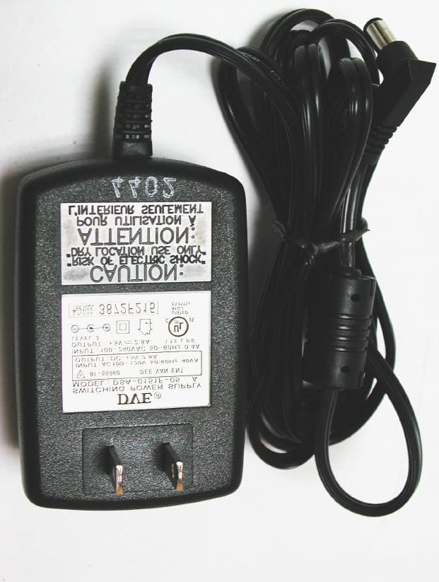
L8G8800005
Apr 24, 2003802.11B WLAN Access Point
Equipment Class
DSS - Part 15 Spread Spectrum Transmitter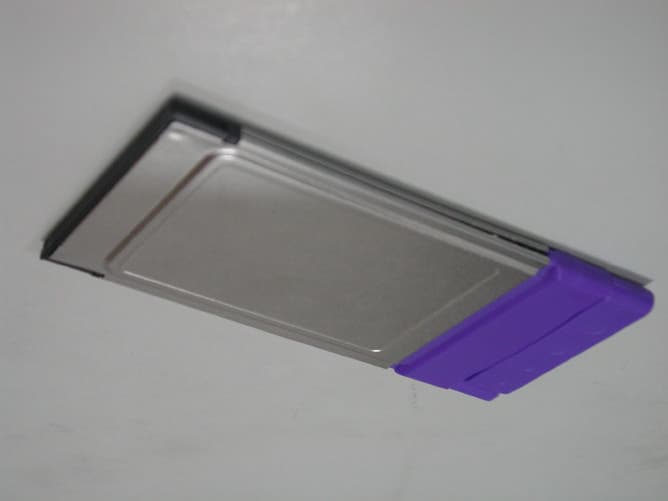
L8G8800003
Dec 03, 2002WLAN CardBus Adapter
Equipment Class
DTS - Digital Transmission System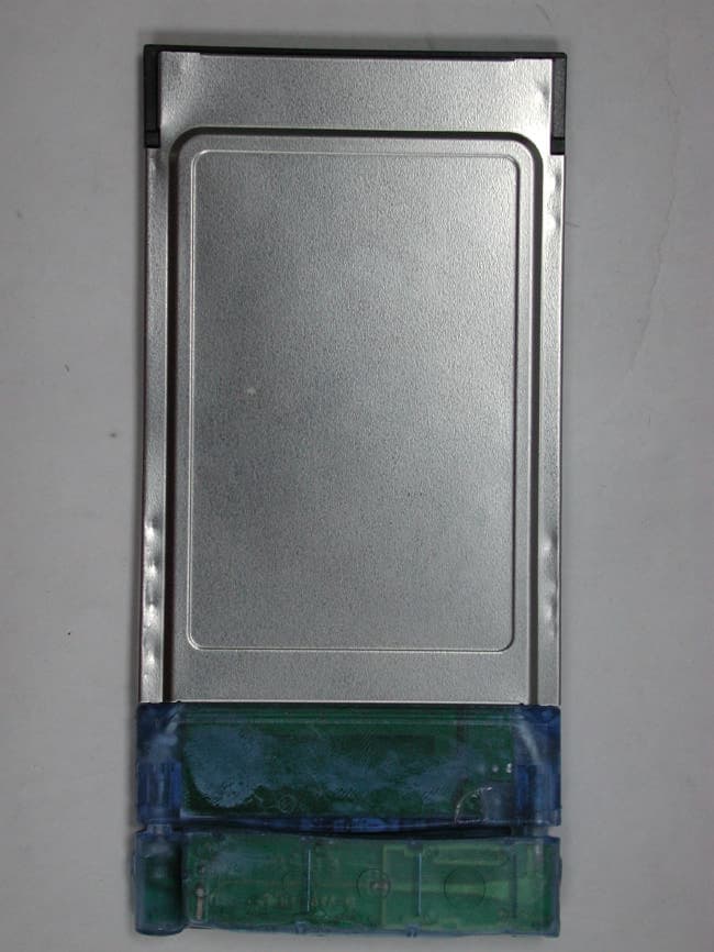
L8G8800001
May 20, 2002PCMCIA Radio Card with Integrated Antenna
Equipment Class
DTS - Digital Transmission System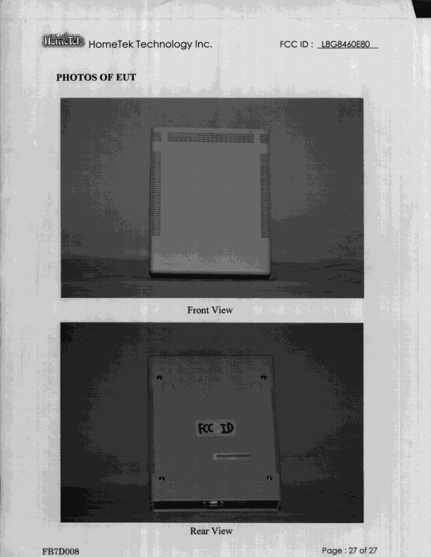
L8G8460E80
Sep 08, 1998JBP - Part 15 Class B Computing Device Peripheral
Equipment Class
JBP - Part 15 Class B Computing Device PeripheralL8G250110
Jan 20, 1998JBP - Part 15 Class B Computing Device Peripheral
Equipment Class
JBP - Part 15 Class B Computing Device Peripheral