L8G8800003WLAN CardBus Adapter
Lantech Advance Corporation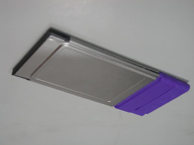
Click to zoom
Application Details
- Equipment Class
- DTS - Digital Transmission System
- Date of Grant
- Dec 03, 2002
- Application Purpose
- Original Equipment
- Date of Application
- Dec 03, 2002
- Equipment Note
- WLAN CardBus Adapter
- Frequency Range
- 2412.00000000 - 2462.00000000
- Company
- Lantech Advance Corporation
- Country
- Taiwan
Documents & Files
Document Text
Text extracted from the exhibit documents filed with the FCC. Open a document above to read the original.
Users Manual
W W L L A A N N C C a a r r d d B B u u s s A A d d a a p p t t e e r r Regulatory notes and statements Wireless LAN, Health and Authorization for use Radio frequency electromagnetic energy is emitted from Wireless LAN devices. The energy levels of these emissions however are far much less than the electromagnetic energy emissions from wireless devices like for example mobile phones. Wireless LAN devices are safe for use frequency safety standards and recommendations. The use of Wireless LAN devices may be restricted in some situations or environments for example: · On board of airplanes, or · In an explosive environment, or · In case the interference risk to other devices or services is perceived or identified as harmful In case the policy regarding the use of Wireless LAN devices in specific organizations or environments (e.g. airports, hospitals, chemical/oil/gas industrial plants, private buildings etc.) is not clear, please ask for authorization to use these devices prior to operating the equipment. Regulatory Information/disclaimers Installation and use of this Wireless LAN device must be in strict accordance with the instructions included in the user documentation provided with the product. Any changes or modifications made to this device that are not expressly approved by the manufacturer may void the user’s authority to operate the equipment. The Manufacturer is not responsible for any radio or television interference caused by unauthorized modification of this device, of the substitution or attachment. Manufacturer and its authorized resellers or distributors will assume no liability for any damage or violation of government regulations arising from failing to comply with these guidelines. USA-FCC (Federal Communications Commission) statement This device complies with Part 15 of FCC Rules. Operation is subject to the following two conditions: 1. This device may not cause interference, and 2. This device must accept any interference, including interference that may cause undesired operation of this device. FCC Radio Frequency Exposure statement This Wireless LAN radio device has been evaluated under FCC Bulletin OET 65C and found compliant to the requirements as set forth in CFR 47 Sections 2.1091, 2.1093, and 15.247 (b) (4) addressing RF Exposure from radio frequency devices. The radiated output power of this Wireless LAN device is far below the FCC radio frequency exposure limits. Nevertheless, this device shall be used in such a manner that the potential for human contact during normal operation is minimized. FCC Interference Statement This equipment has been tested and found to comply with the limits for a Class B digital device, pursuant to Part 15 of the FCC Rules. These limits are designed to provide reasonable protection against harmful interference in a residential installation. This equipment generates, uses, and can radiate radio frequency energy. If not installed and used in accordance with the instructions, it may cause harmful interference to radio communications. However, there is no guarantee that interference will not occur in a particular installation. If this equipment does cause harmful interference to radio or television reception, which can be determined by turning the equipment off and on, the user is encouraged to try and correct the interference by one or more of the following measures: 1. Reorient or relocate the receiving antenna. 2. Increase the distance between the equipment and the receiver. 3. Connect the equipment to an outlet on a circuit different from that to which the receiver is connected. 4. Consult the dealer or an experienced radio/TV technician for help. Export restrictions This product or software contains encryption code which may not be exported or transferred from the US of Canada without an approved US Department of Commerce export license. Safety Statements Federal Communications Commission Statement This device complies with FCC Rules Part 15. Operation is subject to the following two conditions: · This device may not cause harmful interference, and · This device must accept any interference received, including interference that may cause undesired operation. SAFETY INFORMATION Your device contains a low power transmitter. When device is transmitted it sends out radio frequency (RF) signal. Table of Contents 1. Introduction .. ................................................................................... 1 1.1 Package Contents . ..................................................................... . 2 1.2 Advantages for Using Wireless Network .......................................... . 2 2. Step by step Installation Guide . .............................................. ............ 3 2.1 Install WLAN CardBus Adapter Driver for Windows 98, ME, 2000, and XP.............................................. .................. ....................... 3 2.2 Install WLAN CardBus Adapter Utility for Windows 98, ME, 2000, XP 2.3 Wireless LAN Monitor Utillity ....................................................... 5 2.2.1 Setting ........................................................ ..................... .. 6 2.2.2 Statistics .......................................................................... ... 7 2.2.3 Site Survey ............................................................................ 7 2.2.4 Encryption ........................................................... ................. 8 2.2.5 Advanced .................................. ........................................... 9 2.2.6 Version ................................................................................. 10 2.4 Remove your WLAN CardBus Adapter............................................. 12 2.5 Uninstall the WLAN CardBus Adapter Utility / Driver ............................ 12 3. Application ...................................................................................... 13 3.1 File Sharing in Microsoft Windows 98....................................…
Text truncated - open the document above for the full version.
Cover Letter(s)
American Telecommunications Certification Body Inc. 6731 Whittier Ave, McLean, VA 22101 October 8, 2002 RE: FCC ID: l8g8800003 Attention: Eric Wong I have a few comments on this Application. 1 Please note that the following documents are not readable by the FCC server because they contain Asian or other non-English fonts. Block Diagram, Operational description, Parts list, Test Report. Please provide these documents as pdf without Asian or other non-English fonts. xxx 2 The report states that an external antenna is used. (See page 11 of the report). However, all photos of the device show the antenna to be internal to the device. In addition, the schematics show 2 on board antenna(s) and one external antenna port. Please also note that the PCMCIA card has a power in excess of 25mW and is quit capable of being used on the lap within 2.5 cm from the body. As such, the FCC requires SAR testing of this device. Please provide the SAR report for this device in a typical laptop or appropriate device. Alternately, please fully explain the external antenna described in the report and how it is attached to the laptop to insure 20cm separation from the user ( this includes photos of how this is attached to the laptop). You will also have to provide evidence in the schematics of how the internal antennas are disabled so as not to operate. You will also have to revise the manual to show how the antenna(s) are to be attached to the lap top to insure 20cm separation. xxx 3 Please note that the label appears large enough to accommodate the 2-condition statement. Please provide a revised label or please explain why you feel the statement does not need to be on the device. xxx 4 Please explain the use of the external antenna connector J1 in the schematic. See item 2. xxx 5 Please note that as of September 9, 2002 the FCC conducted limits go to 15okHz. If you wish to continue using the older limits, please provide an attestation to 15.37 Transition provisions for compliance with the rules. xxx 6 Please note that the FCC regulatory information in the RF exposure section of the manual is incorrect. The correct FCC document is OET65C not OET64C. Please correct the reference. Also, please note that since this device looks like it requires SAR testing, you will also have to include the maximum SAR values measured during this testing. xxx 7 Please note that since this is a PCMCIA WLAN card and it will be used in a laptop computer PCMCIA slot, there is no way to enforce the caution statement about keeping 20cm distance from the device and the user if the device uses its integral antennae. Also, since this device is greater than 25mW output, it will require SAR testing. This caution statement will have to be changed to reflect the maximum SAR levels measured. Also, the statement will have to be changed to reflect that 2.5cm distance is to be observed when used in a laptop. xxx 8 The non modification statement needs to caution the user that modifying the device may void the users right to use the device. The current statement only states that it may violate FCC regulations but does not address the fact the it may also void the users right to use the device. Please make this statement clear and unambiguous about this issue. xxx Dennis Ward mailto:[email protected] The items indicated above must be submitted before processing can continue on the above referenced application. Failure to provide the requested information may result in application termination. Correspondence should be considered part of the permanent submission and may be viewed from the Internet after a Grant of Equipment Authorization is issued. l Page 2October 8, 2002 Please do not respond to this correspondence using the email reply button. In order for your response to be processed expeditiously, you must submit your documents through the AmericanTCB.com website. Also, please note that partial responses increase processing time and should not be submitted. Any questions about the content of this correspondence should be directed to the sender.
Cover Letter(s)
EMAIL on PPSD Subject: Re: Application of the LANTECH (L8G8800003) Date Sun, 01 Dec 2002 21:40:15 -0800 From: Dennis Ward <[email protected]> To: TRC - Eric <[email protected]> References: Thanks Eric the plot appears as if the spreading sequence has not been turned on. Even with a 1 Mbit transfer rate, the direct sequence spreading sequence would spread the data over a much wider band than shown. The spreading sequence must be turned on and the modulation must be applied. The plot does not convince me that the DSSS device is operating in a normal direct sequence spread spectrum mode, regardless of the data rate. If anything it appears to be simply an FM modulated signal.. Remember that in a DSSS device the modulation from the data is not the primary component. DSSS devices use a wideband direct sequence spreading code to modulate the carrier over a wide band, this is then further modulated with the data stream. Even if little or no data were transmitted, the direct sequence spreading code would produce a much wider band plot that what is shown. Please show a plto with the direct sequence spreading sequenc fully engaged. Thanks Dennis TRC - Eric wrote: Dear Dennis:Thanks for your info...In order to maintain the constant SWT TIME at 100s, the RBW, VBW and SPAN should stand on some kind of ratio as we have done (RBW=3kHz and VBW=10kHz while SPAN=300kHz) The plots show unusual is the result as the the L8G8800003 is measured in 1Mb/sec data rate as the ordinary one is measured at 11Mb/sec, it affects the bandwidth to be plot at this testing items... FYI..Thank you!! Eric -----Original Message----- From: Dennis Ward [mailto:[email protected]] Sent: Sunday, December 01, 2002 7:58 AM To: TRC - Eric Subject: Re: Application of the LANTECH (L8G8800003) Hi Eric ONe last item, please note that your PPSD plots are not in accordance with the FCC approved test methods. While the plots are technically witin the setting mentioned, they do not appear to be plots of what would be typical in a DSSS WLAN device, and brings into question what the device actually is. Please follow the established PPSD test method. Remember that the PPSD is the power spectral density over 1 MHz not 300 kHz. It is then best to have at least a 1MHa span. Thanks Dennis TRC - Eric wrote: Dear Dennis:I have uploaded the materials about your comment of this project.Please do kindly review this and be noted that the ID should be all in BLOCK LETTER instead...Thank you!! Eric EMAIL on Max power Subject: Re: Application of the LANTECH (L8G8800003) Date: Sun, 01 Dec 2002 21:32:11 -0800 From: Dennis Ward <[email protected]> To: TRC - Eric <[email protected]> References: 1 Hi Eric I understand what you are saying, but that does not answer the question. The manufacturer must clearly state what these numbers are and how they relate to the new numbers. The attestation must state clearly that the number 34 is equal to absolutely no more than the measured value in the report (i.e. 24.12mW). This must be clearly shown. Sorry to be so picky, but the FCC will have questions on this issue so it is better answered now rather than risk a dismissal later. Hope you understand Thanks Dennis TRC - Eric wrote: Dear Dennis:The letter states that the FIELD at the firmware (which can be accessed via the Windows) is changed form the 38 to 34, then the power is lowered (as listed in the report) in order to comply with the power threshold of the 24mW... The attestation letter is used for the declarations that the modification will be adapted to all the products entering into the mass production in the future. Thank you!!Eric -----Original Message----- From: Dennis Ward [mailto:[email protected]] Sent: Sunday, December 01, 2002 7:42 AM To: TRC - Eric Subject: Re: Application of the LANTECH (L8G8800003) Hi Eric I am in the process of reviewing your new data. Please notice that the modification letter states "The power value set in the firmware will be reduced -Field "Tx Power" at the firmware will be set from "38" to "34". Please note that I have no idea what "38" to "34" means in power. Please clarify this. Remember, power for this device MUST be lower than 24mW otherwise SAR WILL BE REQUIRED. Please cofirm by that the maximum power for this device will be no greater than 24mW. This should be attested to in power, not in ambiguous terms of firmware setting levels. I may send more requests as I review the documentation you provided. Thanks Dennis TRC - Eric wrote: Dear Dennis:I have uploaded the materials about your comment of this project.Please do kindly review this and be noted that the ID should be all in BLOCK LETTER instead...Thank you!! Eric
Cover Letter(s)
Training Research Co., Ltd. 255 Nanyang Street, Shijr, Taipei Hsien 221, Taiwan, R.O.C. TEL: 886-2-26935155 FAX: 886-2-26934440 Email: [email protected] TRCSince1985 ® November 27, 2002 RE: LANTECH Computer Company FCC ID: L8G8800003 Dear Dennis: After the review of your comments, we have made some response upon your advice; they are summarized as follows: 1. The materials you’d requested to re-sent is uploaded, which have been converted by the Acrobat Distiller and believed that problem-free in reading at the non-Asian environment. (They all named with suffix “*_2”) 2. The description about the antenna is printed by mistake and the correct description of the antenna is “Integral DUAL-WING antenna”, which is a PCB board-antenna with the joint attached with the case. The antenna connector is equipped but disabled (will be blocked by a rubber-cap) as this is the feature in the future model and they will be granted when they are ready to place in the market. 3. We have dropped those 2 conditions on the labels as a remark. The final labels adhere on the product will include those statement in order to comply the rules. 4. The external antenna connector in the schematics is applicable to series of this prototype design and some of them will have different design (maybe with and external antenna via the jack). For the L8G8800003, the connector will leave “open” and disabled (Same as item#2 above). 5. We have re-do the conducted emissions upon the release of the FCC requested. Please find in the uploads. 6. We have asked the LANTECH to have the manual changed as you mentioned. The revised manual is also uploaded. 7. Regarding to this, LANTECH have desired to have the power slightly lowered in order to comply with the 25mW threshold of SAR evaluation. Please find the report with the power measurement after the modification, also the declaration of such modification. (TO BE CONTINUED) Training Research Co., Ltd. 255 Nanyang Street, Shijr, Taipei Hsien 221, Taiwan, R.O.C. TEL: 886-2-26935155 FAX: 886-2-26934440 Email: [email protected] TRCSince1985 ® 8. The statement you’ve requested is already shown on the page 2. Please check it again as the attachment shown. Should you have any questions or more information is requested, please don’t hesitate to ask us. Thank you. Sincerely yours, Eric Wong Project Engineer Training Research Co Ltd.
External Photos
External Photo of the LANTECH 8800-520 External Photo of the LANTECH 8800-520
Internal Photos
Internal Photo of the LANTECH 8800-520 Internal Photo of the LANTECH 8800-520 Internal Photo of the LANTECH 8800-520 Internal Photo of the LANTECH 8800-520 Internal Photo of the LANTECH 8800-520 Internal Photo of the LANTECH 8800-520
Test Report
Test Report ------------------------------------------------------------------------------ 38/42 Report No.: L2715698 Training Research Co., Ltd., TEL: 886-2-26935155, Fax: 886-2-26934440 9.4 Test Result of Power spectral density The following table shows a summary of the highest power spectral density. FCC ID : L8G8800003 EUT : WLAN CardBus Adapter Channel Frequency (GHz) Ppr (dBuV) Cable Loss (dB) Ppq (dBm) Limit (dB) Margin (dB) CH 01 2.413 -2.98 0.20 -2.78 8.00 -10.78 CH 06 2.438 -5.34 0.20 -5.14 8.00 -13.14 CH 11 2.463 -5.98 0.20 -5.78 8.00 -13.78 Note: 1. The attachment follow by this page and there is no page number. 2. Ppr: spectrum read power density (using peak search mode), Ppq: actual peak power density in the spread spectrum band. 3. Ppq = Ppr + |Cable Loss| Test Report ------------------------------------------------------------------------------ 39/42 Report No.: L2715698 Training Research Co., Ltd., TEL: 886-2-26935155, Fax: 886-2-26934440 Channel 01 Test Report ------------------------------------------------------------------------------ 40/42 Report No.: L2715698 Training Research Co., Ltd., TEL: 886-2-26935155, Fax: 886-2-26934440 Channel 06 Test Report ------------------------------------------------------------------------------ 41/42 Report No.: L2715698 Training Research Co., Ltd., TEL: 886-2-26935155, Fax: 886-2-26934440 Channel 11
Test Report
Test Report ------------------------------------------------------------------------------ 1/42 Report No.: L2715698 Training Research Co., Ltd., TEL: 886-2-26935155, Fax: 886-2-26934440 MEASUREMENT REPORT of WLAN CARDBUS ADAPTER Applicant : LANTECH Advance Corporation Model No. : 8800-520 EUT : WLAN CardBus Adapter FCC ID : L8G8800003 Report No. : L2715698 Tested by : Training Research Co., Ltd. TEL : 886-2-26935155 FAX : 886-2-26934440 255 Nanyang St., Shijr, Taipei Hsien, Taiwan, R.O.C. Test Report ------------------------------------------------------------------------------ 3/42 Report No.: L2715698 Training Research Co., Ltd., TEL: 886-2-26935155, Fax: 886-2-26934440 Tables of Contents I. GENERAL ..................................................................................................................... 5 1.1 Introduction .............................................................................................................. 5 1.2 Description of EUT .................................................................................................. 5 1.3 Description of Support Equipment ........................................................................... 6 1.4 Configuration of System Under Test ........................................................................ 7 1.5 Verify the Frequency and Channel ........................................................................... 8 1.6 Test Procedure ......................................................................................................... 9 1.7 Location of the Test Site .......................................................................................... 9 1.8 General Test Condition ............................................................................................ 9 II. Section 15.101(a) : Equipment Authorization of Unintentional Radiators................ 10 III. Section 15.203 : Antenna Requirement........................................................................ 11 IV. Section 15.207 : Power Line Conducted Emissions for AC Powered Units ............. 12 4.1 Test Condition & Setup ........................................................................................... 12 4.2 List of Test Instruments ........................................................................................... 12 4.3 Test Configuration .................................................................................................. 13 4.4 Test Result of Conducted Emissions ....................................................................... 14 V. Section 15.247(a) : Technical Description of the EUT................................................. 16 VI. Section 15.247(a)(2) : Bandwidth for Direct Sequence System ................................. 17 6.1 Test Condition & Setup ........................................................................................... 17 6.2 Test Instruments Configuration ............................................................................... 17 6.3 List of Test Instruments ........................................................................................... 17 6.4 Test Result of Bandwidth ......................................................................................... 18 VII. Section 15.247(b) : Power Output ............................................................................... 22 7.1 Test Condition & Setup ........................................................................................... 23 7.2 List of Test Instruments ........................................................................................... 23 7.3 Test Result .............................................................................................................. 23 VIII.Section 15.247(c) : Spurious Emissions (Radiated) .................................................. 24 8.1 Test Condition & Setup ........................................................................................... 24 8.2 List of Test Instruments ........................................................................................... 25 8.3 Test Instruments Configuration ............................................................................... 26 8.4 Test Result of Spurious Radiated Emissions ........................................................... 27 8.5 Test Result of Bandedge Compliance....................................................................... 34 IX.Section 15.247(d) : Power Spectral Density ................................................................. 37 9.1 Test Condition & Setup ........................................................................................... 37 9.2 Test Instruments Configuration ............................................................................... 37 9.3 List of Test Instruments............................................................................................ 37 Test Report ------------------------------------------------------------------------------ 4/42 Report No.: L2715698 Training Research Co., Ltd., TEL: 886-2-26935155, Fax: 886-2-26934440 9.4 Test Result of Power Spectral Density .................................................................... 38 Appendix A: Set Up Procedure .......................................................................................... 42 Test Report ------------------------------------------------------------------------------ 5/42 Report No.: L2715698 Training Research Co., Ltd., TEL: 886-2-26935155, Fax: 886-2-26934440 . GENERAL 1.1 Introduction The following measurement report is submitted on behalf of Applicant in support of a WLAN CardBus Adapter certification in accordance with Part 2 Subpart J and Part 15 Subpart A and C of the Commission's Rules and Regulations. 1.2 Description of EUT EUT : WLAN CardBus Adapter Model No. : 8800-520 Granted FCC ID : L8G8800003 Frequency Range : 2.412 GHz ~ 2.462GHz Support Channel : 11 Channel Modulation Sk…
Text truncated - open the document above for the full version.
Test Setup Photos
Training Research Co., Ltd. 255 Nanyang Street, Shijr, Taipei Hsien 221, Taiwan, R.O.C. TEL: 886-2-26935155 FAX: 886-2-26934440 TRCSince1985 ® Test setup photos: LANTECH WLAN CardBus Adapter (Test report no.:L2715698) FCC ID: L8G8800003 Test Instruments Configuration of Conducted Emissions Training Research Co., Ltd. 255 Nanyang Street, Shijr, Taipei Hsien 221, Taiwan, R.O.C. TEL: 886-2-26935155 FAX: 886-2-26934440 TRCSince1985 ® Test Instruments Configuration of Bandwidth Test Configuration of Bandwidth for Direct Sequence System P.S.: Notebook computer to control the EUT at maximal power output and channel Number and set antenna kit Test Condition & Setup of Power Output EUT Spectrum Analyzer (RBW:100kHz; VBW: 100kHz) EUT BOONTON 4532 RF Power Meter Training Research Co., Ltd. 255 Nanyang Street, Shijr, Taipei Hsien 221, Taiwan, R.O.C. TEL: 886-2-26935155 FAX: 886-2-26934440 TRCSince1985 ® Test Instruments Configuration of the Spurious Radiated Emissions Front View of the Test Configuration Rear View of the Test Configuration The test configuration for frequency between 1GHz to 18GHz is same as above. Training Research Co., Ltd. 255 Nanyang Street, Shijr, Taipei Hsien 221, Taiwan, R.O.C. TEL: 886-2-26935155 FAX: 886-2-26934440 TRCSince1985 ® Test Instruments Configuration of Power Spectral Density Test Configuration of Power Spectral Density P.S.: Notebook computer to control the EUT at maximal power output and channel number and set antenna kit EUT Spectrum Analyzer (RBW:3kHz; VBW: 10kHz)
Contact Information
Applicant
Jason Chang(Manager/Wireless Comm R&D Dept)
Technical Contact
Training Research Co., Ltd.Eric Wong
[email protected]886-2-26935155
2, Lane 194, Huan Ho Street, Hsichih, · Taipei Hsien, · Taiwan
Non-Technical Contact
Training Research Co., Ltd.Eric Wong
[email protected]886-2-26935155
Test Firm
Training Research Co., Ltd.Jack Tsai
Technical Specifications
| # | Rule Parts | Frequency Range | Power Output |
|---|---|---|---|
| 1 | 15C | 2.41 GHz - 2.46 GHz | 24.20 mW |
Other Applications from Lantech Advance Corporation
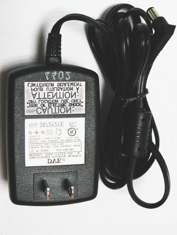
L8G8800005
Apr 24, 2003802.11B WLAN Access Point
Equipment Class
DSS - Part 15 Spread Spectrum Transmitter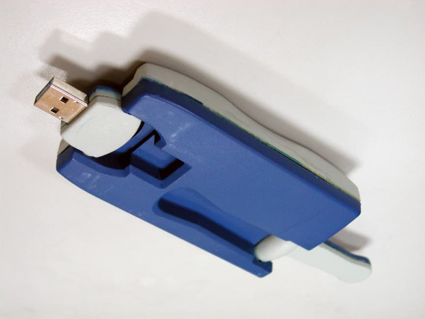
L8G8800002
Jul 26, 2002WLAN USB Adapter
Equipment Class
DSS - Part 15 Spread Spectrum Transmitter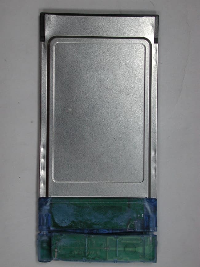
L8G8800001
May 20, 2002PCMCIA Radio Card with Integrated Antenna
Equipment Class
DTS - Digital Transmission System
L8G8460E80
Sep 08, 1998JBP - Part 15 Class B Computing Device Peripheral
Equipment Class
JBP - Part 15 Class B Computing Device PeripheralL8G250110
Jan 20, 1998JBP - Part 15 Class B Computing Device Peripheral
Equipment Class
JBP - Part 15 Class B Computing Device Peripheral