LA5WERB001Remote Bypass Transmitter
Senior Technologies Inc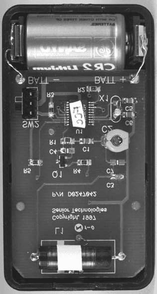
Click to zoom
Application Details
- Equipment Class
- DCD - Part 15 Low Power Transmitter Below 1705 kHz
- Date of Grant
- Sep 14, 1998
- Application Purpose
- Original Equipment
- Date of Application
- Jul 26, 1998
- Equipment Note
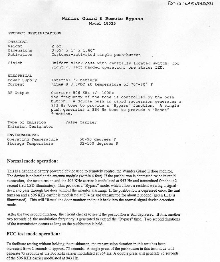
- Remote Bypass Transmitter
- Frequency Range
- 0.50600000 - 0.50600000
- Company
- Senior Technologies Inc
- Country
- United States
Documents & Files
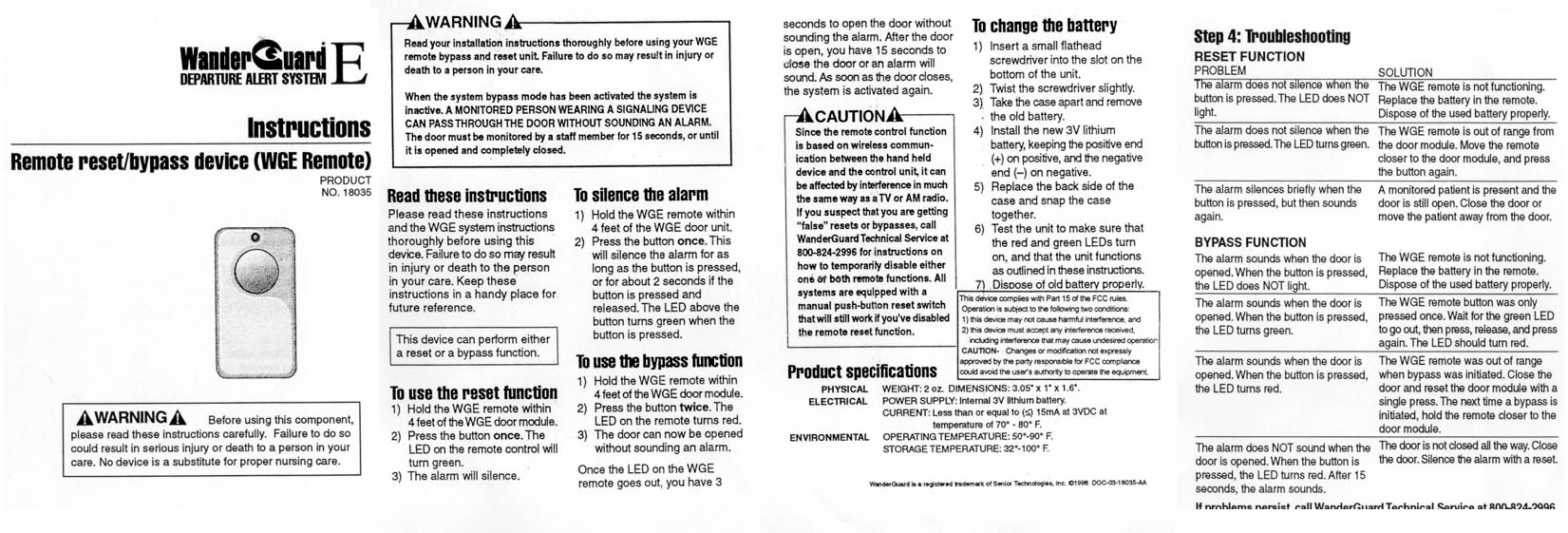
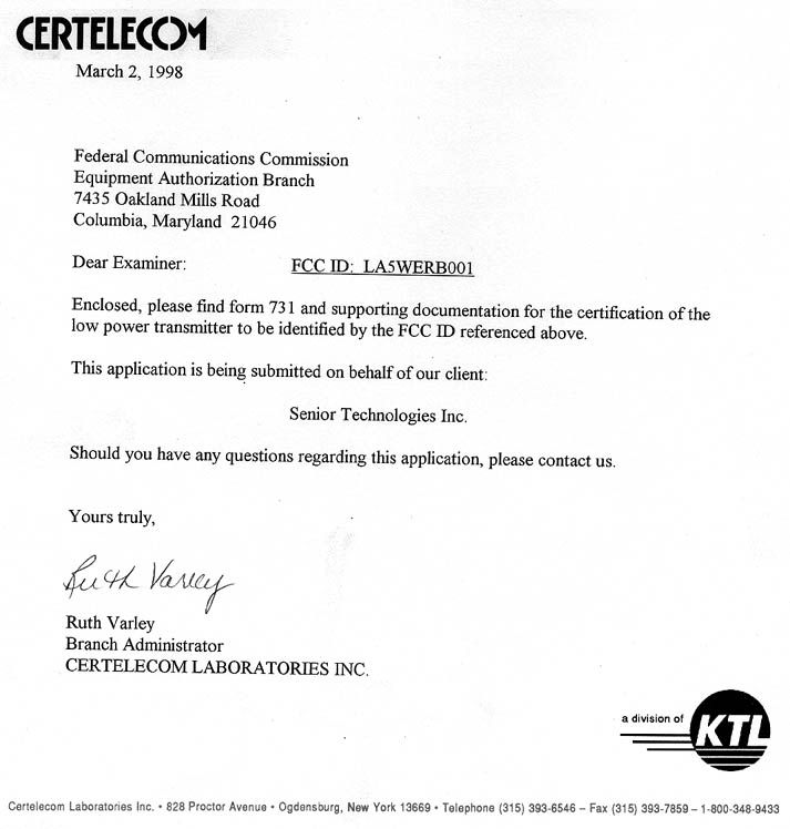
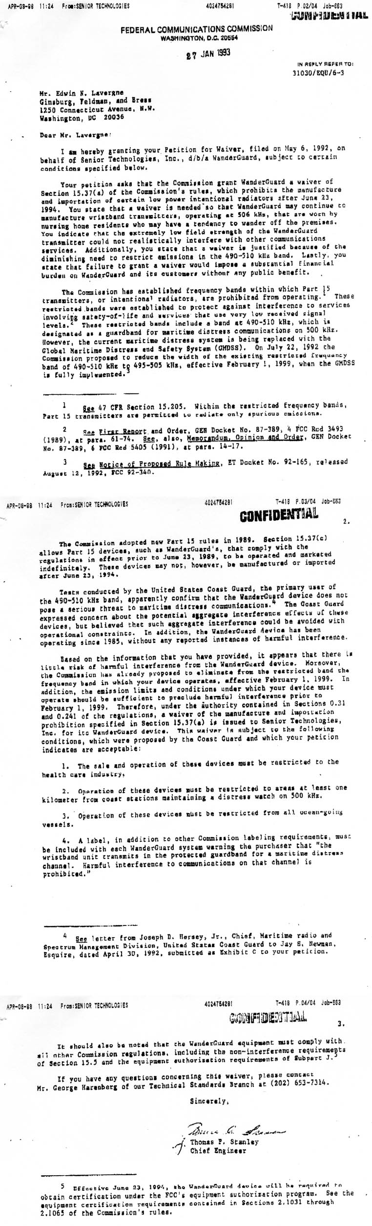
Document Text
Text extracted from the exhibit documents filed with the FCC. Open a document above to read the original.
External Photos
Figure 1 - EXTERNAL VIEW FRONT Figure 2 - EXTERNAL VIEW BACK SHOWING LABEL LOCATION Figure 3 - PCB FRONT VIEW Figure 4 - PCB REAR VIEW
ID Label/Location Info
Figure 1 - LABEL LOCATION
Test Report
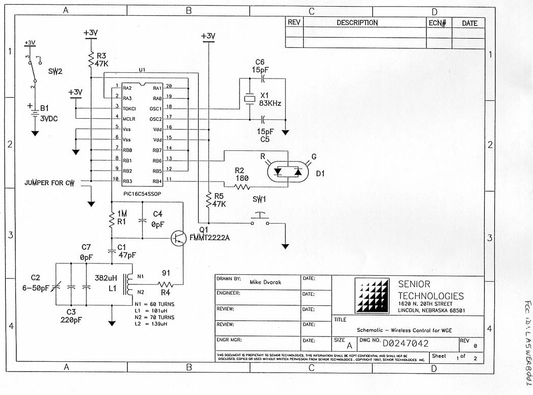
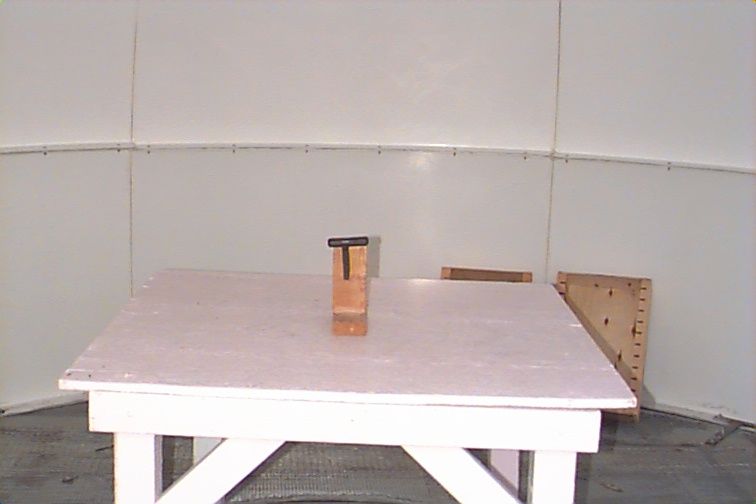
Certelecom Laboratories Inc. Safety - EMI - Telecom - ISO Guide 25 ENGINEERING TEST REPORT ON: THE SENIOR TECHNOLOGIES “WANDER GUARD REMOTE BYPASS”, MODEL: 18035 FCC ID: LA5WERB001 IN ACCORDANCE WITH: FCC PART 15, SUBPART C PARAGRAPH 15.209 FOR LOW FREQUENCY TRANSMITTERS PROJECT NO.: 7R00505 TESTED FOR: SENIOR TECHNOLOGIES INC. PO BOX 80238 LINCOLN, NE 68501 USA TESTED BY: CERTELECOM LABORATORIES INC. 3325 RIVER ROAD, R.R. 5 OTTAWA, ONTARIO K1V 1H2 FEBRUARY 1998 This document contains 10 pages including this one. Certelecom Laboratories Inc. authorizes the above named company to reproduce this report provided it is reproduced in its entirety and for use by the company’s employees only. Any use which a third party makes of this report, or any reliance on or decisions to be made based on it, are the responsibility of such third parties. Certelecom Laboratories Inc. accepts no responsibility for damages, if any, suffered by any third party as a result of decisions made or actions based on this report. This report applies only to the items tested. KTL - Certelecom Laboratories Inc. FCC PART 15, SUBPART C PROJECT NO.: 7R00505 EQUIPMENT: The Senior Technologies “WanderGuard E Remote Bypass” Model: 18035 FCC ID: LA5WERB001 Page 2 of 10 EQUIPMENT:WanderGuard E Remote Bypass MODEL NO.: 18035 SERIAL NO.: None GENERAL: These tests were conducted on a sample of the equipment for the purpose of demonstrating compliance with FCC Part 15, Subpart C for Transmitters operating under the general limits of Paragraph 15.209. All tests were conducted in accordance with ANSI C63.4. Radiated measurements were made on an open area test site. A description of the test facility is on file with the FCC. ABSTRACT: NAME OF TESTPARA. NO.RESULTS Conducted Emissions15.207(a)Not Applicable Radiated Emissions15.209Complies THIS TEST REPORT RELATES ONLY TO THE ITEM(S) TESTED. THE FOLLOWING DEVIATIONS FROM, ADDITIONS TO, OR EXCLUSIONS FROM THE TEST SPECIFICATIONS HAVE BEEN MADE. Conducted Emissions were not performed because the equipment is battery powered. TESTED BY:___________________________________ DATE:______________ Wayne Clarke, Technologist APPROVED BY:________________________________ DATE:______________ W. Waterhouse, RF Engineering Lab Manager KTL - Certelecom Laboratories Inc. FCC PART 15, SUBPART C PROJECT NO.: 7R00505 EQUIPMENT: The Senior Technologies “WanderGuard E Remote Bypass” Model: 18035 FCC ID: LA5WERB001 Page 3 of 10 GENERAL EQUIPMENT INFORMATION TRANSMITTER Frequency Range: 506 kHz Frequency of Sample Tested: 506 kHz Tunable Bands: One Number of Channels: One Channel Spacing: Not Applicable Emission Designator: 54K8P0N Crystal Frequencies: 83 kHz User Frequency Adjustment: None Power Requirement:3 Vdc Lithium Battery KTL - Certelecom Laboratories Inc. FCC PART 15, SUBPART C PROJECT NO.: 7R00505 EQUIPMENT: The Senior Technologies “WanderGuard E Remote Bypass” Model: 18035 FCC ID: LA5WERB001 Page 4 of 10 KTL - Certelecom Laboratories Inc. FCC PART 15, SUBPART C PROJECT NO.: 7R00505 EQUIPMENT: The Senior Technologies “WanderGuard E Remote Bypass” Model: 18035 FCC ID: LA5WERB001 Page 5 of 10 NAME OF TEST: Conducted EmissionsPARA. NO.: 15.107 TESTED BY:DATE: TEST CONDITIONS: Standard Temperature and Humidity Standard Test Voltage MINIMUM STANDARD: Frequency(MHz)Maximum Powerline Conducted RF Voltage μ μμ μ VdB μ μμ μ V 0.45 - 30.025048 TEST RESULTS:Complies/Does Not Comply. See attached graphs. MEASUREMENT DATA:See attached graphs. METHOD OF MEASUREMENT (PROCEDURE ANSI C63.4-1992) Measurements were made using a spectrum analyzer with 10 kHz RBW, Peak detector. Any emissions that are close to the limit are measured using a test receiver with 10 kHz bandwidth, CISPR Quasi-Peak detector. Broadband emissions are identified by switching the receiver detector function from Quasi-Peak to Average. If the amplitude of the emission drops by 6 dB or more then the emission is classified as broadband and the Quasi-Peak level is reduced by a factor of 13 dB. KTL - Certelecom Laboratories Inc. FCC PART 15, SUBPART C PROJECT NO.: 7R00505 EQUIPMENT: The Senior Technologies “WanderGuard E Remote Bypass” Model: 18035 FCC ID: LA5WERB001 Page 6 of 10 NAME OF TEST: Radiated EmissionsPARA. NO.: 15.209 TESTED BY: Wayne ClarkeDATE: February 18, 1998 TEST CONDITIONS: Outdoor Range Standard Test Voltage MINIMUM STANDARD:The field strength of emissions from the device shall not exceed the following limits: Frequency (MHz) Field Strength ( μ μμ μ V/m) Field Strength (dB μ μμ μ V/m @ 3m) 0.009 - 0.4902400/ F (kHz) @ 300m-------------------------------------- 0.490 - 1.70524000/ F (kHz) @ 30m-------------------------------------- 1.705 - 3030 @ 30m-------------------------------------- 30 - 8810040.0 88 - 21615043.5 216 - 96020046.0 Above 96050054.0 TEST RESULTS:Complies. The worst-case emission level is 6.9dBμV/m @ 3m at 0.506MHz. This is 40.5dB below the specification limit. MEASUREMENT DATA:See attached table. LIMIT:24000= 47.4 dBuV 506 The E.U.T. was searched to the 10 th harmonic. The noise floor was sufficient to measure 20dB down from limit line. The E.U.T was test on three orthogonal axis to determine worst- case orientation. KTL - Certelecom Laboratories Inc. FCC PART 15, SUBPART C PROJECT NO.: 7R00505 EQUIPMENT: The Senior Technologies “WanderGuard E Remote Bypass” Model: 18035FCC ID: LA5WERB001 Page 7 of 10 STANDARD: FCC Part 15, Subpart C E.U.T. S/N.: None DETECTOR: Average TESTED BY: Wayne Clarke TEST DISTANCE(metres): 3 ANTENNA: Active Loop DATE: February 18, 1998 TEST RECEIVER: ESH3002 ANTENNA MODEL: HFH2-Z2 E.U.T. MODEL NO.: 18035 RECEIVER BW: 10 kHz ANTENNA S/N.: FA000631 FREQ. POL. ANTENNA TABLE RECEIVED ANTENNA AMP DIST. FIELD LIMIT MARGIN HEIGHT AZIMUTH SIGNAL FACTOR GAIN CORR. STRENGTH (MHz) (V/H) (m) (Degrees) (dBuV) (dB)* (dB)** (dB) (dBuV/m) (dBuV/m) (dB) 0.506 V 46.9 -40 6.9 47.4 40.5 H +V HVHVHVHVHVHVH NOTES: * Includes cable loss when amplifier is not used.** Includes cable loss.+ The E.U.T. was searched to …
Text truncated - open the document above for the full version.
Contact Information
Applicant
Gina Bennett
Technical Contact
KTL Ottawa Inc.Thomas N Tidwell
[email protected]800-563-6336
3325 River Rd. · Ottawa, Ontario · Canada
Non-Technical Contact
KTL Ottawa, Inc.Ruth Varley
[email protected]800-563.6336
Test Firm
Nemko Canada Inc.Stuart Beck
Technical Specifications
| # | Rule Parts | Frequency Range | Power Output | Tolerance |
|---|---|---|---|---|
| 1 | 15C | 0.506 MHz - 0.506 MHz | - | % |
Other Applications from Senior Technologies Inc

LA5-BCP1
Jul 28, 2013A pressure sensing switch in a bed or chair pad controls RF messages in the BedCheck Cordless Pad Transmitter
Equipment Class
DSC - Part 15 Security/Remote Control Transmitter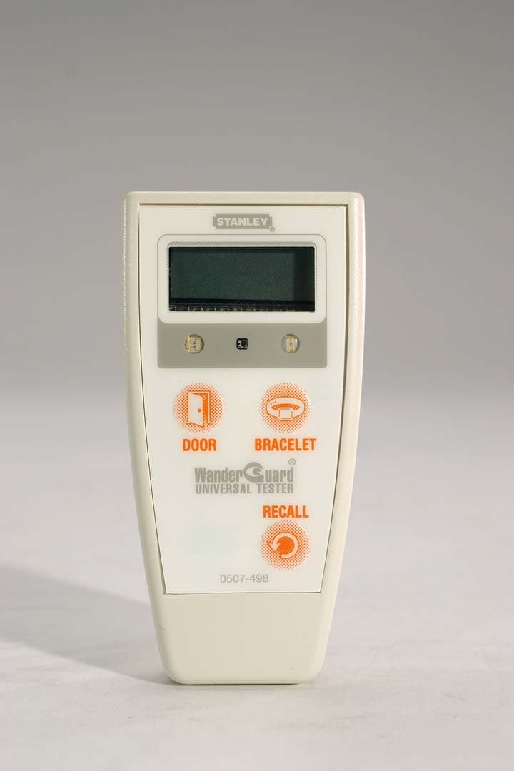
LA5IDUT002
Sep 10, 2006WanderGuard Universal Tester
Equipment Class
DXX - Part 15 Low Power Communication Device Transmitter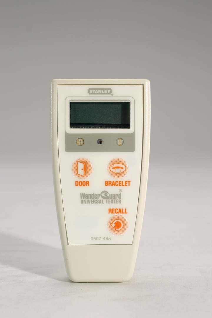
LA5IDUT001
Feb 07, 2006Door Monitor
Equipment Class
DCD - Part 15 Low Power Transmitter Below 1705 kHz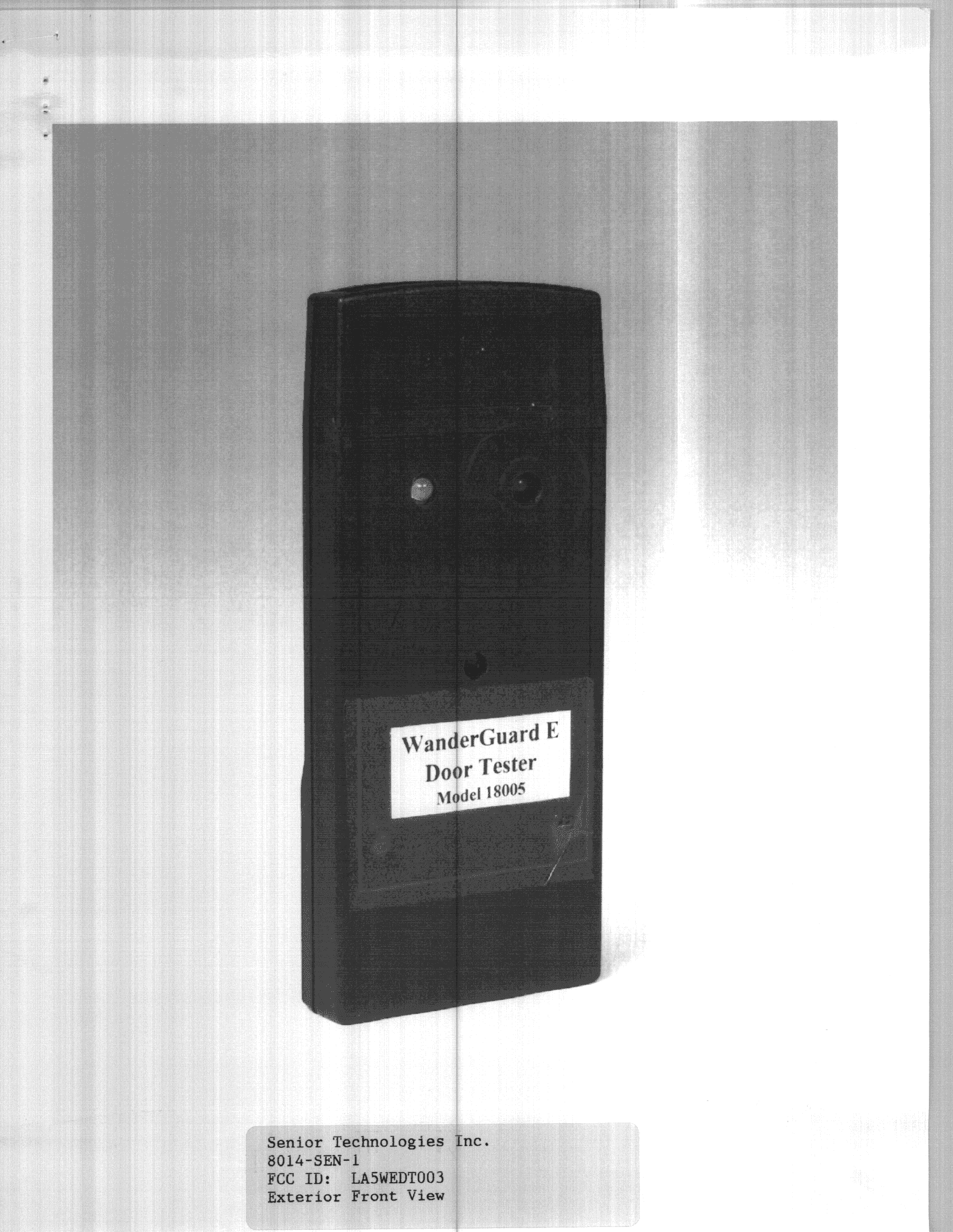
LA5WEDT003
Jul 17, 2000DCD - Part 15 Low Power Transmitter Below 1705 kHz
Equipment Class
DCD - Part 15 Low Power Transmitter Below 1705 kHz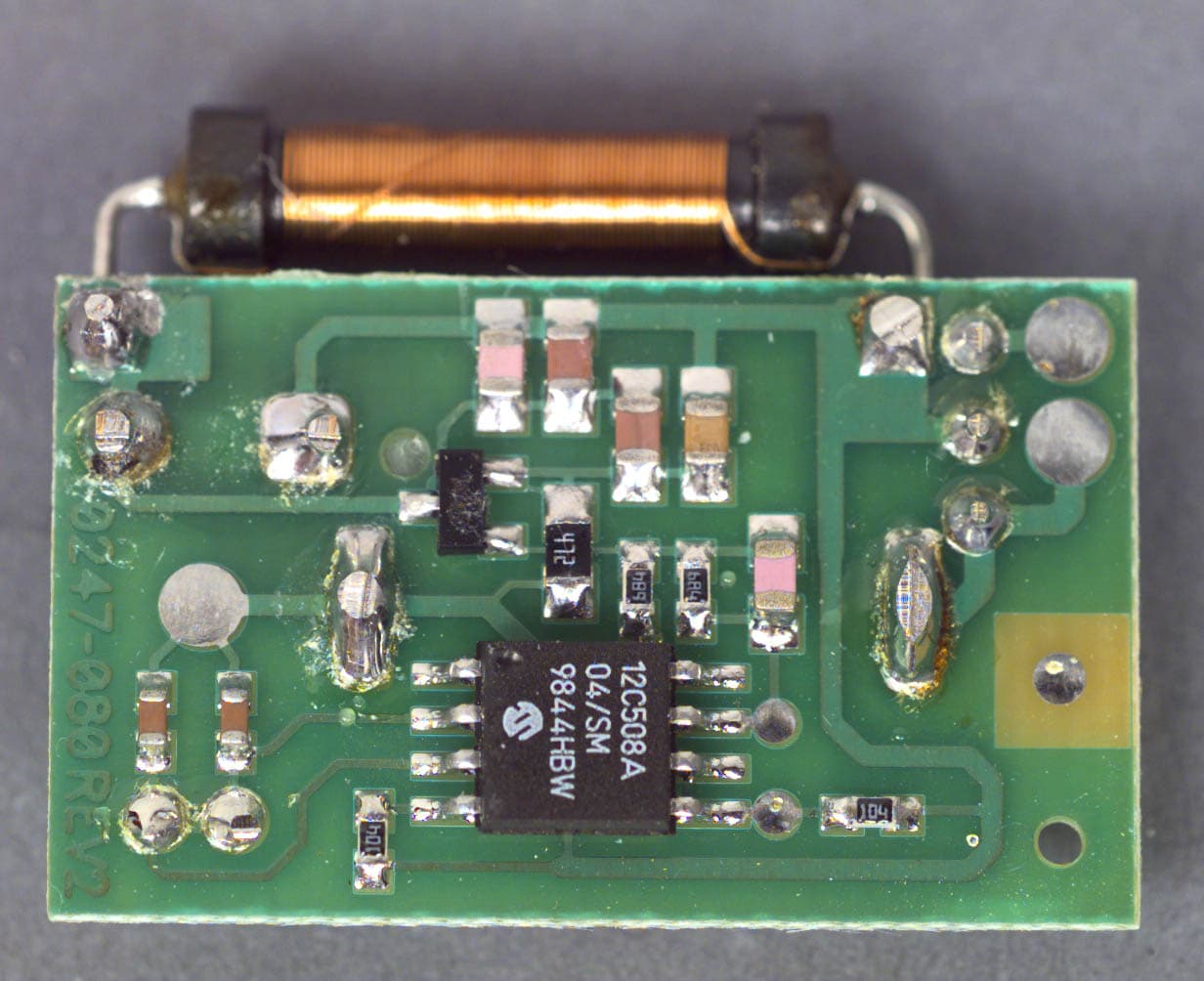
LA5SWSD005
Apr 03, 2000WanderGuard E+ Transmitter
Equipment Class
DCD - Part 15 Low Power Transmitter Below 1705 kHz