LCGFWR3XWELLevel Probing Radar
Endress and Hauser SE Co. KG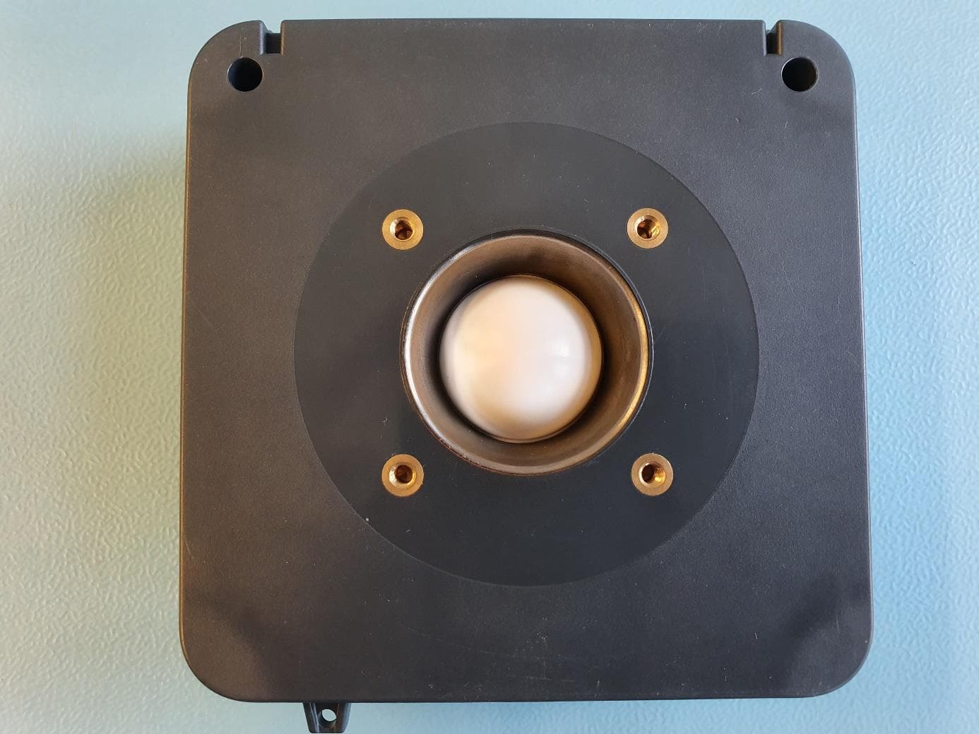
Click to zoom
Application Details
- Equipment Class
- LPR - Level Probing Radar
- Date of Grant
- May 18, 2020
- Application Purpose
- Original Equipment
- Date of Application
- May 18, 2020
- Equipment Note
- Level Probing Radar
- Frequency Range
- 79000.00000000 - 83000.00000000
- Company
- Endress and Hauser SE Co. KG
- Country
- Germany
Documents & Files
Document Text
Text extracted from the exhibit documents filed with the FCC. Open a document above to read the original.
Users Manual
ProductsSolutionsServices Operating Instructions Micropilot FWR30 Free space radar Battery-operated level sensor for monitoring remote and mobile applications BA01991F/00/EN/02.19 71461923 2019-12-18 Micropilot FWR30 2Endress+Hauser Order code: Ext. ord. cd.: Ser. no.: www.endress.com/deviceviewer Endress+Hauser Operations App XXXXXXXXXXXX XXXXX-XXXXXX XXX.XXXX.XX Serial number 1. 3. 2. A0023555 • Make sure the document is stored in a safe place such that it is always available when working on or with the device. • To avoid danger to individuals or the facility, read the "Basic safety instructions" section carefully, as well as all other safety instructions in the document that are specific to working procedures. • The manufacturer reserves the right to modify technical data without prior notice. Your Endress+Hauser sales organization will supply you with current information and updates to these instructions. Micropilot FWR30Table of contents Endress+Hauser3 Table of contents 1 About this document................4 1.1 Document function.....................4 1.2 Symbols .............................4 1.3 Documentation........................5 2 Basic safety instructions ............6 2.1 Requirements for the personnel............6 2.2 Designated use........................6 2.3 Workplace safety.......................6 2.4 Operational safety......................6 2.5 Product safety.........................7 2.6 IT security............................7 3 Product description ................8 3.1 Product design ........................8 4 Incoming acceptance and product identification ......................9 4.1 Incoming acceptance....................9 4.2 Product identification ...................9 4.3 Storage and transport ...................9 5 Installation .......................10 5.1 Mounting the measuring device...........10 5.2 Post-installation check .................12 6 Electrical connection ..............13 6.1 Connecting the measuring device..........13 7 Operation options .................14 7.1 Overview of operation options............14 8 Commissioning ...................15 8.1 Preparatory steps .....................15 8.2 Function check .......................15 8.3 Powering up the measuring device .........15 8.4 Configuration management ..............15 9 Operation ........................16 9.1 Initiating the measurement..............16 9.2 Reading measured values................16 9.3 Displaying the measured value history ......16 9.4 Use cases............................16 10 Diagnostics and troubleshooting ... 18 10.1 Diagnostics information via LED ..........18 10.2 Status signals........................18 10.3 Status symbol (symbol for event level)......18 10.4 List of diagnostic events.................19 11 Maintenance .....................20 11.1 Maintenance tasks ....................20 12 Repair ............................21 12.1 Return..............................21 12.2 Disposal............................21 13 Accessories .......................22 13.1 Device-specific accessories ...............22 14 Technical data ....................23 14.1 Input ..............................23 14.2 Output .............................24 14.3 Environment ........................24 14.4 Process .............................25 Index ..................................26 About this documentMicropilot FWR30 4Endress+Hauser 1 About this document 1.1 Document function These Operating Instructions contain all the information that is required in various phases of the life cycle of the device: from product identification, incoming acceptance and storage, to mounting, connection, operation and commissioning through to troubleshooting, maintenance and disposal. 1.2 Symbols 1.2.1 Safety symbols DANGER This symbol alerts you to a dangerous situation. Failure to avoid this situation will result in serious or fatal injury. WARNING This symbol alerts you to a dangerous situation. Failure to avoid this situation can result in serious or fatal injury. CAUTION This symbol alerts you to a dangerous situation. Failure to avoid this situation can result in minor or medium injury. NOTICE This symbol contains information on procedures and other facts which do not result in personal injury. 1.2.2 Communication symbols 1.2.3 Symbols for certain types of information Permitted: Procedures, processes or actions that are permitted. Forbidden: Procedures, processes or actions that are forbidden. Micropilot FWR30About this document Endress+Hauser5 Additional information: Reference to documentation: Reference to page: Series of steps: 1. , 2. , 3. Result of an individual step: 1.2.4 Symbols in graphics Item numbers: 1, 2, 3 ... Series of steps: 1. , 2. , 3. Views: A, B, C, ... 1.3 Documentation All available documents can be downloaded using: • the serial number of the device (see cover page for description) or • the data matrix code of the device (see cover page for description) or • the "Downloads" area of the website www.endress.com 1.3.1 Supplementary device-dependent documentation Additional documents are supplied depending on the device version ordered: Always comply strictly with the instructions in the supplementary documentation. The supplementary documentation is an integral part of the device documentation. Basic safety instructionsMicropilot FWR30 6Endress+Hauser 2 Basic safety instructions 2.1 Requirements for the personnel The personnel for installation, commissioning, diagnostics and maintenance must fulfill the following requirements: ‣ Trained, qualified specialists must have a relevant qualification for this specific function and task ‣ Are authorized by the plant owner/operator ‣ Are familiar with federal/national regulations ‣ Before beginning work, the specialist staff must have read and understood the instructions in the Operating Instructions and supplementary documentation as well as in the certificates (depending on the application) ‣ Follow instructions and comply with conditions…
Text truncated - open the document above for the full version.
Users Manual
Battery-operated level sensor for monitoring remote and mobile applications Application • Degree of protection: IP66/IP68 • Maximum measuring range: 15 m (49 ft) • Ambient temperature:–20 to +60 °C (–4 to +140 °F) • Connectivity: NB-IoT, LTE-M, 2G • Accuracy: 10 mm (0.39 in) Your benefits • Transparency - easy monitoring of level and location of applications • Flexible and secure integration into cloud platforms, such as Netilion or SupplyCare • Easy commissioning and flexible installation • Reliable 80 GHz radar sensor ProductsSolutionsServices Technical Information Micropilot FWR30 Free space radar TI01499F/00/EN/03.20 71473542 2020-03-23 Micropilot FWR30 2Endress+Hauser Table of contents About this document ........................3 Symbols ...................................3 Function and system design ...................3 Measuring principle ...........................3 Input ....................................4 Measured variable ............................4 Measuring range .............................4 Operating frequency...........................4 Blocking distance .............................4 Operable flow range ...........................4 Output ...................................5 Output signal ................................5 Protocol-specific data ..........................5 Power supply ..............................5 Supply voltage ...............................5 Performance characteristics ..................6 Reference operating conditions....................6 Maximum measured error .......................6 Influence of ambient temperature ..................6 Installation ...............................6 Mounting location ............................6 Mounting kit ................................8 Beam angle .................................9 Environment ..............................9 Ambient temperature range......................9 Storage temperature ...........................9 Humidity ..................................9 Climate class ................................9 Operating altitude according to DIN EN 61010-1 Ed. 3 ...10 Degree of protection..........................10 Vibration and shock resistance ...................10 Electromagnetic compatibility ....................10 Process ..................................10 Mechanical construction ....................10 Dimensions ................................10 Weight ...................................11 Materials .................................11 Human interface ..........................12 Operating concept ............................12 Certificates and approvals ...................12 CE mark...................................12 RoHS.....................................12 EN 302729-1/2 radio standard...................12 FCC......................................13 Industry Canada.............................13 Radiofrequency radiation exposure information........14 Radio approval ..............................14 Other standards and guidelines ...................14 Ordering information.......................14 Accessories ..............................14 Device-specific accessories ......................14 Supplementary documentation...............15 Supplementary device-dependent documentation.......15 Micropilot FWR30 Endress+Hauser3 About this document SymbolsSafety symbols DANGER This symbol alerts you to a dangerous situation. Failure to avoid this situation will result in serious or fatal injury. WARNING This symbol alerts you to a dangerous situation. Failure to avoid this situation can result in serious or fatal injury. CAUTION This symbol alerts you to a dangerous situation. Failure to avoid this situation can result in minor or medium injury. NOTICE This symbol contains information on procedures and other facts which do not result in personal injury. Communication symbols Symbols for certain types of information Permitted: Procedures, processes or actions that are permitted. Forbidden: Procedures, processes or actions that are forbidden. Additional information: Reference to documentation: Reference to page: Series of steps: 1. , 2. , 3. Result of an individual step: Symbols in graphics Item numbers: 1, 2, 3 ... Series of steps: 1. , 2. , 3. Views: A, B, C, ... Function and system design Measuring principle The Micropilot is a "downward-looking" measuring system, operating based on the time-of-flight method (ToF). It measures the distance from the reference point to the product surface. Radar pulses are emitted by an antenna, reflected off the product surface and received again by the radar system. Micropilot FWR30 4Endress+Hauser Input Measured variableMeasured process variables • Level: 0 to 15 m (0 to 49 ft) ±10 mm (0.39 in) • Ambient temperature: –20 to +60 °C (–4 to +140 °F) with an accuracy of ± 2 °C (4 °F) • Position: Angle of device to the horizontal The measurement is perpendicular to the product surface Range: 0 to 180° Measuring range 0 to 15 m (0 to 49 ft) A A0040731 ADistance to level surface Level in mm = tank empty - distance to level surface Level in % = (tank empty - distance to level surface) / tank full ⋅ 100 % Tank empty = from the measuring device to the bottom Tank full = from the bottom to the measuring device Operating frequency 80 GHz Blocking distance BD 8° A0041499 • No signals are analyzed within the blocking distance (BD) For this reason, the blocking distance can be used to suppress interference signals (e.g. from condensate) near the antenna • Factory setting: 0 mm • The blocking distance (BD) can be defined in the cloud or set automatically The setting is made in the blocking distance parameter The following formula is used for the automatic setting: Empty tank - full tank - 100 mm (3.94 in) = blocking distance (min. 0 mm) Operable flow range The sensitivity of the sensor can be configured using a "sensitivity parameter" (high, medium, low). Micropilot FWR30 Endress+Hauser5 Output Output signal Cellular radio NB-IoT, LTE-M with 2G fallback • 2G GPRS/EDGE • 4G LT…
Text truncated - open the document above for the full version.
External Photos
FWR30 external photo FWR30, picture 1: FWR30, picture 2: FWR30, picture 3:
ID Label/Location Info
Released 961004305A000 -1:1 -- Nameplate cCSAus (CA) General Purpose Micropilot FWR30 - DIN A4 05.03.2020 - 08.03.2020 - FRONTB FRONTB - GÄTZIL - 1/1 Refer to protection notice ISO 16016 Classification Title Material SAP material no.FormatSheet WeightkgVolumecm³ No. of documentVersionDoc. part Status Approval contr. Pressure contr. Released Number of changesWelding contr. Drawing chng. Notif. no. Designed ScaleTolerance 1234 A B C D E F 1 5 9 10 19 21 20 26 29 33 38 Micropilot Order code: 6338P87C98A Ser. no.: Ext. ord. cd.: IP68 / 66 Type 4X / 6P Encl. LTE-M1/NB1/EGPRS IMEI xxxxxxxxxxxxxxx Ta: -20...+60°C 50 Dat :e 2020-03 if modification see sep. label X = FW: 01.00.00 Dev.Rev.: 1 ex works C US Field no. Contents Comment 1 Made in Germany, 79689 Maulburg, Hauptstr. 1 Assembled in USA. Greenwood. In. Depending on production plant 5 Order code Ident.-no. = individual no for same devices 9 - 33 optional markings not relevant to CSA approval Lettering/Beschriftung: Wiping resistant according to/wischfest nach DIN EN 61010-1 part/Abschnitt 5.3 07.05.2020 08.05.2020 GÄTZIL IC ID: 10224A-201709BG96 Contains FCC ID: XMR201707BG96 / MODEL FWR30 IC:2519A-WEL FCC ID LCGFWR3XWEL
Internal Photos
FWR30 internal photo Communication module top: Communication module bottom: Sensor module top: Sensor module bottom: Subassembly FWR30: Whole product DN80 (before casting):
RF Exposure Info
© CTC advanced GmbH Page 1 of 4 BNetzA - CAB - 02/21 - 102 D - P L - 1 2 0 7 6 - 0 1 - 0 3 Maximum Permissible Exposure (MPE) & Exposure evaluation Report identification number: 1-9242/19-01-12 MPE (FCC_ISED) Certification numbers and labeling requirements FCC ID LCGFWR3XWEL ISED number 2519A-WEL HVIN (Hardware Version Identification Number) FWR30 PMN (Product Marketing Name) FWR30 FVIN (Firmware Version Identification Number) -/- HMN (Host Marketing Name) -/- This report is electronically signed and valid without handwriting signature. For verification of the electronic signatures, the public keys can be requested at the testing laboratory. Document authorised: Alexander Hnatovskiy Marco Scigliano Lab Manager Testing Manager Radio Communications & EMC Radio Communications & EMC Report no.: 1-9242/19-01-12 © CTC advanced GmbH Page 2 of 4 EUT technologies: Technologies: Max. measured EIRP [dBm] Max. declared EIRP [dBm] # GSM 850 32.4 (slotted peak) 29.4 (avg) 30.0 (avg) A PCS 1900 29.6 (slotted peak) 26.6 (avg) 27.0 (avg) LTE FDD 2 Cat M1 / NB-IoT 1900 MHz 19.2 dBm 20.0 B LTE FDD 4 Cat M1 / NB-IoT 1750 MHz 22.7 dBm 23.0 LTE FDD 5 Cat M1 / NB-IoT 850 MHz 21.5 dBm 22.0 80 GHz Radar 20.52 (peak) 21 (peak) C Details and origins of the measurements shown in the table above: # Results from: Additional information A 1-9242/19-01-07 CTC Advanced GmbH Max measured EIRP GSM 850 page 18, Max measured EIRP PCS 1900 page 26 B 1-9242/19-01-08 CTC Advanced GmbH Max measured EIRP LTE FDD 2 page 17, 24 Max measured EIRP LTE FDD 4 page 32, 39 Max measured EIRP LTE FDD 5 page 47, 54 C TR-50511-74558-02 (Edition 2) TÜV SÜD Product Service GmbH Max peak EIRP page 22 Report no.: 1-9242/19-01-12 © CTC advanced GmbH Page 3 of 4 Prediction of MPE limit at given distance - FCC Equation from page 18 of OET Bulletin 65, Edition 97-01 S = PG / 4π R 2 where: S = Power density P = Power input to the antenna G = Antenna gain R = Distance to the center of radiation of the antenna PG = Output Power including antenna gain The table below is excerpted from Table 1B of 47 CFR 1.1310 titled “Limits for Maximum Permissible Exposure (MPE), Limits for General Population/Uncontrolled Exposure” Frequency Range (MHz) Power Density (mW/cm 2 ) Averaging Time (minutes) 300 -1500 f/1500 30 1500 - 100000 1.0 30 where f = Frequency (MHz) Prediction: worst case Technologies: GSM LTE RADAR Frequency (MHz) 850 850 80000 PG Declared max power (EIRP) 30 22 21 dBm R Distance 20 20 20 cm S MPE limit for uncontrolled exposure 0.5667 0.5667 1.0000 mW/cm 2 Calculated Power density: 0.1990 0.0315 0.0251 mW/cm² Calculated percentage of Limit: 35.13% 5.57% 2.51% This prediction demonstrates the following: The power density levels for FCC at a distance of 20 cm are below the maximum levels allowed by regulations. Report no.: 1-9242/19-01-12 © CTC advanced GmbH Page 4 of 4 Prediction of MPE limit at given distance - ISED RSS-102, Issue 5, 2.5.2 RF exposure evaluation is required if the separation distance between the user and/or bystander and the device’s radiating element is greater than 20 cm, except when the device operates as follows: • below 20 MHz and the source-based, time-averaged maximum e.i.r.p. of the device is equal to or less than 1 W (adjusted for tune-up tolerance); • at or above 20 MHz and below 48 MHz and the source-based, time-averaged maximum e.i.r.p. of the device is equal to or less than 4.49/ƒ 0.5 W (adjusted for tune-up tolerance), where ƒ is in MHz; • at or above 48 MHz and below 300 MHz and the source-based, time-averaged maximum e.i.r.p. of the device is equal to or less than 0.6 W (adjusted for tune-up tolerance); • at or above 300 MHz and below 6 GHz and the source-based, time-averaged maximum e.i.r.p. of the device is equal to or less than 1.31 x 10 -2 ƒ 0.6834 W (adjusted for tune-up tolerance), where ƒ is in MHz; • at or above 6 GHz and the source-based, time-averaged maximum e.i.r.p. of the device is equal to or less than 5 W (adjusted for tune-up tolerance). Prediction: worst case GSM LTE RADAR Frequency 850 850 80000 MHz R Distance 20 20 20 cm P G Maximum EIRP 30 22 21 dBm P G Maximum EIRP 1000.0 158.5 125.9 mW Exclusion Limit from above: 1.32 1.32 5.00 W Calculated percentage of Limit: 75.99% 12.04% 2.52% Conclusion: RF exposure evaluation is not required.
Test Report
TÜV SÜD Product Service GmbH Äußere Frühlingstraße 45 94315 Straubing Germany Phone: +49 9421 5522-0 Fax: +49 9421 5522-99 Web: www.tuev-sued.de Test Report No. TR-50511-74558-02 (Edition 2) Annex C Page 1 of 3 Pages Annex C Antenna Diagrams Antenna diagram as provided by the applicant in the E-plane TÜV SÜD Product Service GmbH Äußere Frühlingstraße 45 94315 Straubing Germany Phone: +49 9421 5522-0 Fax: +49 9421 5522-99 Web: www.tuev-sued.de Test Report No. TR-50511-74558-02 (Edition 2) Annex C Page 2 of 3 Pages Antenna diagram as provided by the applicant in the H-plane TÜV SÜD Product Service GmbH Äußere Frühlingstraße 45 94315 Straubing Germany Phone: +49 9421 5522-0 Fax: +49 9421 5522-99 Web: www.tuev-sued.de Test Report No. TR-50511-74558-02 (Edition 2) Annex C Page 3 of 3 Pages
Test Report
TÜV SÜD Product Service GmbH Äußere Frühlingstraße 45 94315 Straubing Germany Phone: +49 9421 5522-0 Fax: +49 9421 5522-99 Web: www.tuev-sued.de Test Report No. TR-50511-74558-02 (Edition 2) Annex B Page 1 of 20 Pages Annex B Plots Taken During Test B.1 Occupied Bandwidth B.1.1 Occupied Bandwidth (99 %) TÜV SÜD Product Service GmbH Äußere Frühlingstraße 45 94315 Straubing Germany Phone: +49 9421 5522-0 Fax: +49 9421 5522-99 Web: www.tuev-sued.de Test Report No. TR-50511-74558-02 (Edition 2) Annex B Page 2 of 20 Pages B.1.2 Occupied Bandwidth (-10 dBc) TÜV SÜD Product Service GmbH Äußere Frühlingstraße 45 94315 Straubing Germany Phone: +49 9421 5522-0 Fax: +49 9421 5522-99 Web: www.tuev-sued.de Test Report No. TR-50511-74558-02 (Edition 2) Annex B Page 3 of 20 Pages B.2 Band of operation Test plot for -20 °C, 3.6 V TÜV SÜD Product Service GmbH Äußere Frühlingstraße 45 94315 Straubing Germany Phone: +49 9421 5522-0 Fax: +49 9421 5522-99 Web: www.tuev-sued.de Test Report No. TR-50511-74558-02 (Edition 2) Annex B Page 4 of 20 Pages Test plot for -10 °C, 3.6 V TÜV SÜD Product Service GmbH Äußere Frühlingstraße 45 94315 Straubing Germany Phone: +49 9421 5522-0 Fax: +49 9421 5522-99 Web: www.tuev-sued.de Test Report No. TR-50511-74558-02 (Edition 2) Annex B Page 5 of 20 Pages Test plot for 0 °C, 3.6 V TÜV SÜD Product Service GmbH Äußere Frühlingstraße 45 94315 Straubing Germany Phone: +49 9421 5522-0 Fax: +49 9421 5522-99 Web: www.tuev-sued.de Test Report No. TR-50511-74558-02 (Edition 2) Annex B Page 6 of 20 Pages Test plot for +10 °C, 3.6 V TÜV SÜD Product Service GmbH Äußere Frühlingstraße 45 94315 Straubing Germany Phone: +49 9421 5522-0 Fax: +49 9421 5522-99 Web: www.tuev-sued.de Test Report No. TR-50511-74558-02 (Edition 2) Annex B Page 7 of 20 Pages Test plot for +20 °C,3.06 V TÜV SÜD Product Service GmbH Äußere Frühlingstraße 45 94315 Straubing Germany Phone: +49 9421 5522-0 Fax: +49 9421 5522-99 Web: www.tuev-sued.de Test Report No. TR-50511-74558-02 (Edition 2) Annex B Page 8 of 20 Pages Test plot for +20 °C, 3.6 V TÜV SÜD Product Service GmbH Äußere Frühlingstraße 45 94315 Straubing Germany Phone: +49 9421 5522-0 Fax: +49 9421 5522-99 Web: www.tuev-sued.de Test Report No. TR-50511-74558-02 (Edition 2) Annex B Page 9 of 20 Pages Test plot for +30 °C, 3.6 V TÜV SÜD Product Service GmbH Äußere Frühlingstraße 45 94315 Straubing Germany Phone: +49 9421 5522-0 Fax: +49 9421 5522-99 Web: www.tuev-sued.de Test Report No. TR-50511-74558-02 (Edition 2) Annex B Page 10 of 20 Pages Test plot for +40 °C, 3.6 V TÜV SÜD Product Service GmbH Äußere Frühlingstraße 45 94315 Straubing Germany Phone: +49 9421 5522-0 Fax: +49 9421 5522-99 Web: www.tuev-sued.de Test Report No. TR-50511-74558-02 (Edition 2) Annex B Page 11 of 20 Pages Test plot for +50 °C, 3.6 V TÜV SÜD Product Service GmbH Äußere Frühlingstraße 45 94315 Straubing Germany Phone: +49 9421 5522-0 Fax: +49 9421 5522-99 Web: www.tuev-sued.de Test Report No. TR-50511-74558-02 (Edition 2) Annex B Page 12 of 20 Pages B.3 Fundamental Emissions EIRP TÜV SÜD Product Service GmbH Äußere Frühlingstraße 45 94315 Straubing Germany Phone: +49 9421 5522-0 Fax: +49 9421 5522-99 Web: www.tuev-sued.de Test Report No. TR-50511-74558-02 (Edition 2) Annex B Page 13 of 20 Pages B.4 Radiated Emissions All emissions show more than 20 dB margin to the limi – no values noted 20 30 40 50 60 70 80 90 100 110 120 130 9k203050100 k2003005001M2M3M5M10M2030M Level in dB μV/m Frequency in H z P re view 1- P K+FC C 15.20 9 mag (3 m)Fin al_Res ult P K + 0 5 10 15 20 25 30 35 40 45 50 55 60 65 70 75 80 30M 5060 80100 M200300400500 8001G Level in dB μV/m Frequency in H z P re view R esult 1V-P K+P re view R esult 1H-P K+ FC C P art 15C E lectric Field S trengt h 3m Q PFin al_Res ult QP K TÜV SÜD Product Service GmbH Äußere Frühlingstraße 45 94315 Straubing Germany Phone: +49 9421 5522-0 Fax: +49 9421 5522-99 Web: www.tuev-sued.de Test Report No. TR-50511-74558-02 (Edition 2) Annex B Page 14 of 20 Pages 0 5 10 15 20 25 30 35 40 45 50 55 60 65 70 75 80 1G2G3G4G5G6 8 10G13G Level in dB μV/m Frequency in H z P re view R esult 2 V-A V GP re view R esult 1V-P K+ P re view R esult 2 H-A V GP re view R esult 1H-P K+ FC C P art 15C E lectric Field S trengt h 3m P KFC C P art 15C E lectric Field S trengt h 3m A V Fin al_Res ult P K +Fin al_Res ult CA V 10 15 20 25 30 35 40 45 50 55 60 65 70 75 80 85 90 13 13,5 14 14,5 15 15,5 16 16,5 17 17,5 18 Level in dB μV/m Frequency in GHz P re view R esult 2 V-A V GP re view R esult 1V-P K+ P re view R esult 2 H-A V GP re view R esult 1H-P K+ FC C P art 15C E lectric Field S trengt h 1m P KFC C P art 15C E lectric Field S trengt h 1m A V Fin al_Res ult P K +Fin al_Res ult CA V TÜV SÜD Product Service GmbH Äußere Frühlingstraße 45 94315 Straubing Germany Phone: +49 9421 5522-0 Fax: +49 9421 5522-99 Web: www.tuev-sued.de Test Report No. TR-50511-74558-02 (Edition 2) Annex B Page 15 of 20 Pages 0 5 10 15 20 25 30 35 40 45 50 55 60 65 70 75 80 18G 30G40G Level in dB μV/m Frequency in H z P re view R esult 2 V-A V GP re view R esult 1V-P K+ P re view R esult 2 H-A V GP re view R esult 1H-P K+ Crit ical_F reqs A VGCrit ical_F reqs P K+ FC C P art 15C E lectric Field S trengt h 3m P KFC C P art 15C E lectric Field S trengt h 3m A V Fin al_Res ult P K +Fin al_Res ult CA V M a xP eak -P K+ ( Single)A ve rage-A VG (S ingle) CA verage -CA V (Single ) TÜV SÜD Product Service GmbH Äußere Frühlingstraße 45 94315 Straubing Germany Phone: +49 9421 5522-0 Fax: +49 9421 5522-99 Web: www.tuev-sued.de Test Report No. TR-50511-74558-02 (Edition 2) Annex B Page 16 of 20 Pages Peak Average 10 15 20 25 30 35 40 45 50 55 60 65 70 75 80 85 90 40 42 44 46 48 50 52 54 56 58 60 Level in dB μV/m Frequency in GHz P re view R esult 1H-P K+P re view R esult 1V-P K+ FC C 15.20 9 (1m) P KFin al_Res ult P K + 10 15 20 25 30 35 40 45 50 55 60 65 70 75 80 85 90 40 42 44 46 48 50 52 54 56 58 60 Level in dB μV/m Frequency in GHz P re view R esult 1H-P K+P re view R esult 1V-P K+FC C 15.…
Text truncated - open the document above for the full version.
Test Report
Note: The test data of this report is related only to the individual item which has been tested. This report shall not be reproduced except in full extent without the written approval of the testing laboratory. Trade Register Munich HRB 85742 VAT ID No. DE129484267 Information pursuant to Section 2(1) DL-InfoV (Germany) at www.tuev-sued.com/imprint Managing Directors: Dr. Peter Havel (CEO) Dr. Jens Butenandt Phone: +49 9421 55 22-0 Fax: +49 9421 55 22-99 www.tuev-sued.de TÜV SÜD Product Service GmbH Äußere Frühlingstraße 45 94315 Straubing Germany Prüfbericht / Test Report Nr. / No. TR-50511-74558-02 (Edition 2) Applicant: Endress + Hauser GmbH + Co. KG Type of equipment: Level Probing Radar Type designation: FWR30 Order No.: 196/1017781463 Test standards: FCC Code of Federal Regulations, CFR 47, Part 15, Sections 15.205, 15.207, 15.209 and 15.256 (partly) ISED RSS-211 Issue 1, Sections 5.1 and 5.2(partly) ISED RSS-GEN Issue 5, Sections 8.8, 8.9 and 8.10 (Category I Equipment) February 13, 2020 Page 1 of 39 TÜV SÜD Product Service GmbH Äußere Frühlingstraße 45 94315 Straubing Germany Phone: +49 9421 5522-0 Fax: +49 9421 5522-99 Web: www.tuev-sued.de Test Report No. TR-50511-74558-02 (Edition 2) Page 2 of 39 Pages Table of Contents 1 Description of the Equipment Under Test (EUT) ........................................... 3 2 Administrative Data ....................................................................................... 4 3 Identification of the Test Laboratory .............................................................. 5 4 Summary ....................................................................................................... 6 5 Operation Mode and Configuration of EUT ................................................... 7 6 Measurement Procedures ............................................................................. 8 6.1 Bandwidth Measurements....................................................................... 8 6.2 Radiated Emission Measurement 9 kHz to 30 MHz ................................ 9 6.3 Radiated Emission in Fully or Semi Anechoic Room ............................ 11 6.4 Radiated Emission at Alternative Test Site ........................................... 14 7 Test Results ................................................................................................ 16 7.1 Occupied Bandwidth ............................................................................. 18 7.2 Designation of Emissions ...................................................................... 20 7.3 Band of Operation ................................................................................. 21 7.4 Fundamental Emissions EIRP .............................................................. 22 7.5 Radiated Emission Measurement 9 kHz to 30 MHz .............................. 24 7.6 Radiated Emission Measurement 30 MHz to 200 GHz ........................ 25 7.7 RF Exposure Requirement.................................................................... 27 7.8 Exposure of Humans to RF Fields ........................................................ 28 8 Referenced Regulations .............................................................................. 32 9 Test Equipment List with Calibration Data ................................................... 34 10 Measurement Uncertainty ........................................................................... 35 11 Revision History .......................................................................................... 39 Annex A Photographs Taken During Testing ............................................ 3 pages Annex B Plots Taken During Test ........................................................... 20 pages Annex C Antenna Diagrams ...................................................................... 2 pages TÜV SÜD Product Service GmbH Äußere Frühlingstraße 45 94315 Straubing Germany Phone: +49 9421 5522-0 Fax: +49 9421 5522-99 Web: www.tuev-sued.de Test Report No. TR-50511-74558-02 (Edition 2) Page 3 of 39 Pages 1 Description of the Equipment Under Test (EUT) General data of EUT Type designation 1 : FWR30 Parts 2 : Serial number(s): FWR30_1095 Manufacturer: Endress + Hauser GmbH + Co. KG Type of equipment: Level Probing Radar Version: As received FCC ID: LCGFWR3XWEL IC: 2519A-WEL Additional parts/accessories: Technical data of EUT Application frequency range: 75 GHz - 85 GHz Frequency range: 79 GHz – 81 GHz Operating frequency: 79 GHz Type of modulation: FMCW Pulse train: N/A Pulse width: N/A Number of RF-channels: 1 Channel spacing: N/A Designation of emissions 3 : 4G0XXN Type of antenna: Integrated Size/length of antenna: N/A Connection of antenna: detachable not detachable Type of power supply: Battery supply Specifications for power supply: nominal voltage: 3.6 V 1 Type designation of the system if EUT consists of more than one part. 2 Type designations of the parts of the system, if applicable. 3 Also known as "Class of Emission". TÜV SÜD Product Service GmbH Äußere Frühlingstraße 45 94315 Straubing Germany Phone: +49 9421 5522-0 Fax: +49 9421 5522-99 Web: www.tuev-sued.de Test Report No. TR-50511-74558-02 (Edition 2) Page 4 of 39 Pages 2 Administrative Data Application details Applicant (full address): Endress + Hauser GmbH + Co. KG Hauptstraße 1 79689 Maulburg Germany Contact person: Mr. Ralf Reimelt Order number: 196/1017781463 Receipt of EUT: 2019-11-20; 2019-12-13 Date(s) of test…
Text truncated - open the document above for the full version.
Contact Information
Applicant
Ralf Reimelt(R&D Radar Level Measurement)
Test Firm
TUV SUD Product Service GmbHMarkus Biberger
Technical Specifications
| # | Rule Parts | Frequency Range | Power Output |
|---|---|---|---|
| 1 | 15.256 | 79.00 GHz - 83.00 GHz | 113.00 mW |
Other Applications from Endress and Hauser SE Co. KG
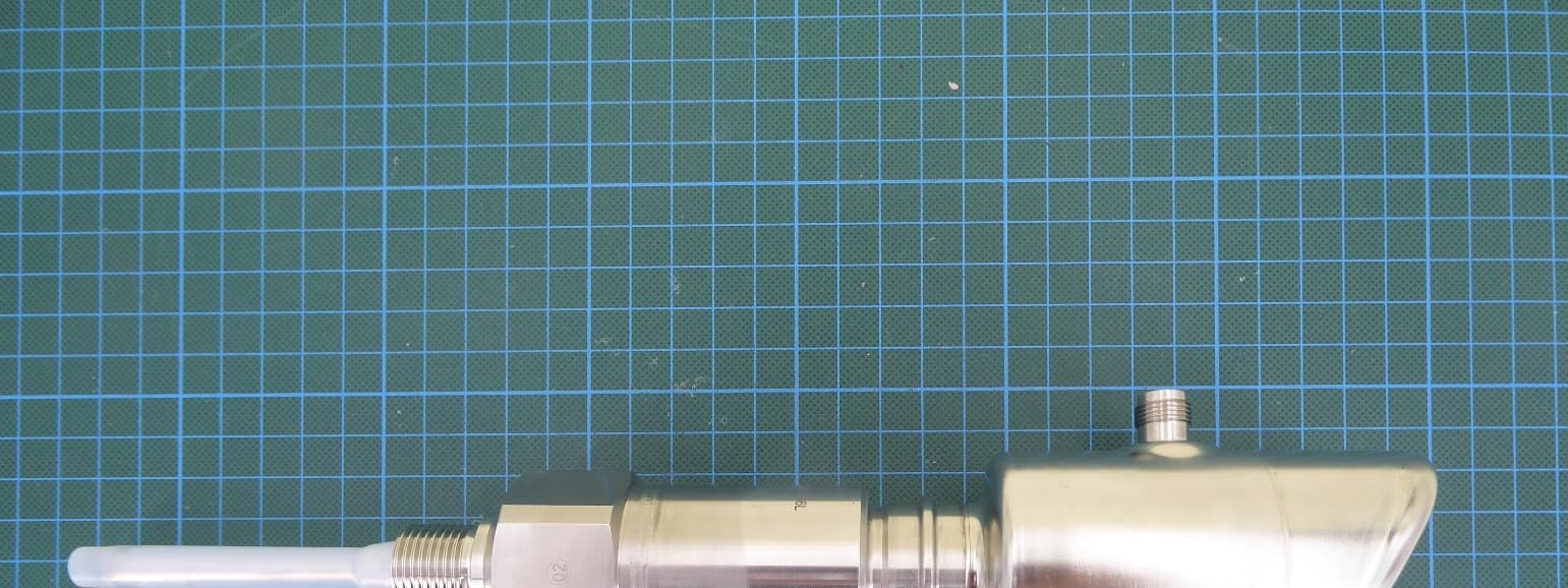
LCGFMI43
Jul 29, 2026Capacitive level sensor with BLE communication
Equipment Class
DTS - Digital Transmission System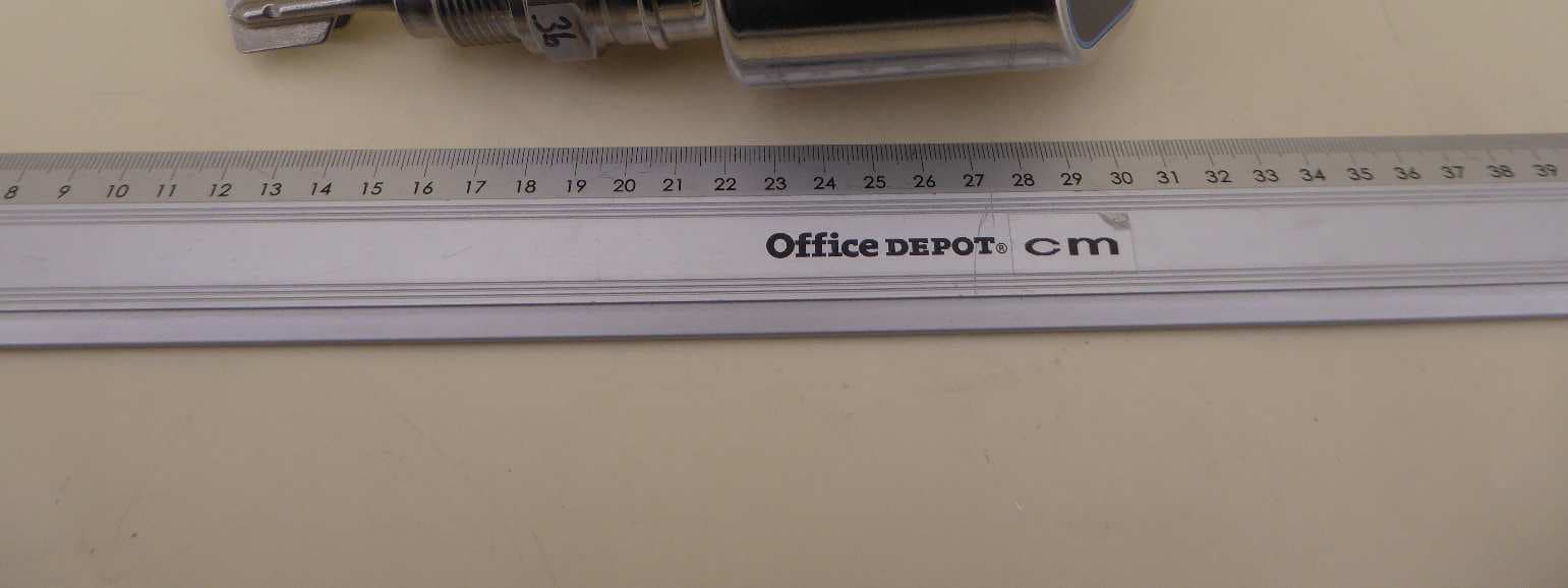
LCGFTL4X
Nov 28, 2024Hygienic point level switch for liquids with BLE TX
Equipment Class
DTS - Digital Transmission System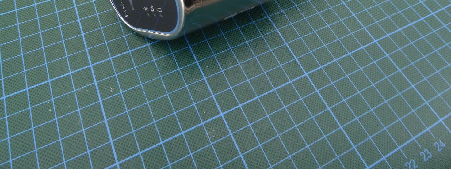
LCGFMR43L
Aug 07, 2024Level Probing Radar
Equipment Class
DXX - Part 15 Low Power Communication Device Transmitter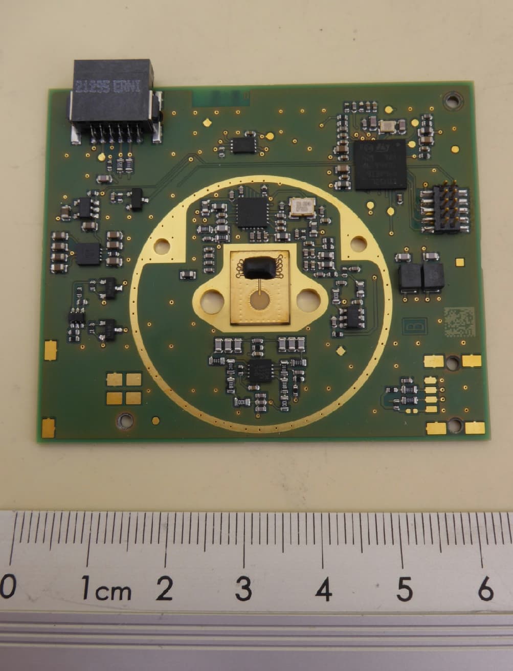
LCGUXR3XYEL
Oct 29, 2023Level Probing Radar
Equipment Class
LPR - Level Probing Radar
LCGVU113
Mar 11, 2020BTLE Display
Equipment Class
DTS - Digital Transmission System