LCGUXR3XYELLevel Probing Radar
Endress and Hauser SE Co. KG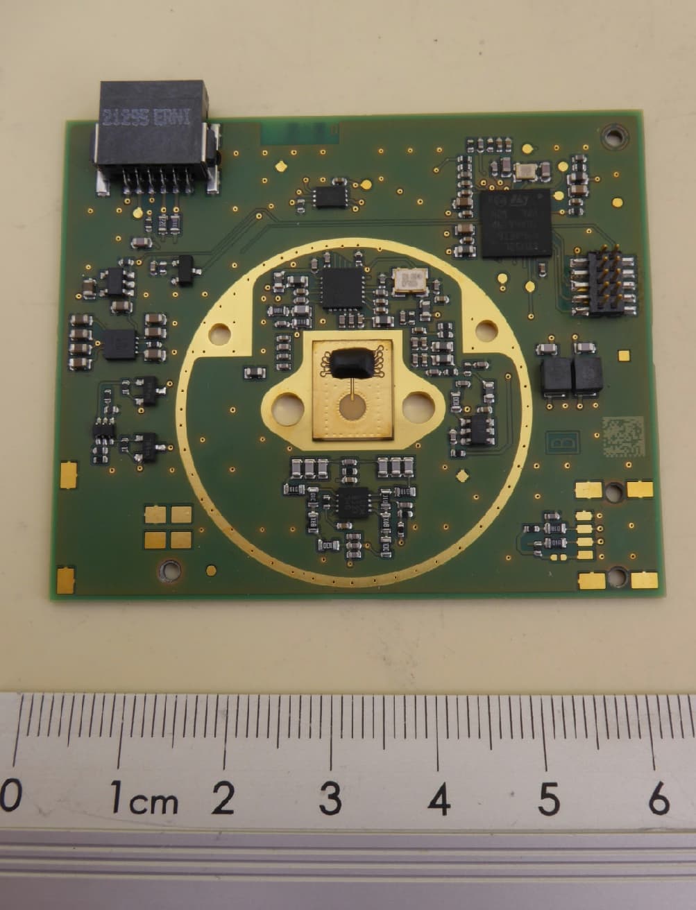
Click to zoom
Application Details
- Equipment Class
- LPR - Level Probing Radar
- Date of Grant
- Oct 29, 2023
- Application Purpose
- Original Equipment
- Date of Application
- Oct 29, 2023
- Equipment Note
- Level Probing Radar
- Frequency Range
- 75000.00000000 - 82000.00000000
- Company
- Endress and Hauser SE Co. KG
- Country
- Germany
Documents & Files
Document Text
Text extracted from the exhibit documents filed with the FCC. Open a document above to read the original.
Users Manual
Remarks: Project: / - / USR30 Status: Date: Author: Released 18.08.2023 M. Sautermeister, M. Buscemi, A. Lopatin Version: Document number: File name: Page: - 420023807 USR30_Customer_Manual_-.docx 1 of 20 Template: DWP Version 1 All rights reserved. Passing on and copying of this document, use and communication of its contents is not permitted without written authorization from Endress+Hauser SE+Co. KG . Classification : PUBLIC Alle Rechte vorbehalten. Das Kopieren dieses Dokuments und die Verwendung von Teilen aus diesem Doku- ment ist ohne schriftliche Genehmigung der Endress+Hauser SE+Co. KG nicht erlaubt. Customer Manual USR30 Customer Manual USR30 Version: Document number: File name: Page: - 420023807 USR30_Customer_Manual_-.docx 2 of 20 All rights reserved. Passing on and copying of this document, use and communication of its contents is not permitted without written authorization from Endress+Hauser SE+Co. KG . Classification : PUBLIC Alle Rechte vorbehalten. Das Kopieren dieses Dokuments und die Verwendung von Teilen aus diesem Doku- ment ist ohne schriftliche Genehmigung der Endress+Hauser SE+Co. KG nicht erlaubt. Table of contents 1 Introduction 4 1.1 General functionality 4 1.2 Typical applications 5 2 Specification 5 2.1 General specification 5 2.2 Electrical specification 5 2.2.1 Power supply 5 2.2.2 DC/AC characteristics for digital inputs and outputs 5 2.3 Mechanical specification 6 3 Electrical connection 7 4 Sequence/Timing 8 5 Communication 9 5.1 Protocol 9 5.1.1 Request 9 5.1.2 Response 10 5.2 Parameters 10 5.3 Examples of Communication with USR30 11 5.3.1 Configuration 11 5.3.1.1 Write empty distance 11 5.3.1.2 Write full distance 11 5.3.1.3 Write blocking distance 12 5.3.1.4 Write sensitivity 12 5.3.1.5 Write medium type 12 5.3.2 Information data 12 5.3.2.1 Read hardware revision 12 5.3.2.2 Read build number 12 5.3.2.3 Read serial number 13 5.3.3 Trigger measurement 13 5.3.3.1 Write trigger measurement 13 5.3.4 Measured values 13 5.3.4.1 Read distance 13 5.3.4.2 Read measurement quality 13 5.3.4.3 Read error state 13 5.3.4.4 Read level 13 6 Offset Calibration 14 7 Echo Curve 14 7.1 Reading 14 7.2 Scaling 15 7.2.1 X-Axis 15 7.2.2 Y-Axis 16 8 Installation 17 9 Getting Started 18 9.1 Requirements 18 9.2 Using the demo software 18 9.2.1 User interface 18 Customer Manual USR30 Version: Document number: File name: Page: - 420023807 USR30_Customer_Manual_-.docx 3 of 20 All rights reserved. Passing on and copying of this document, use and communication of its contents is not permitted without written authorization from Endress+Hauser SE+Co. KG . Classification : PUBLIC Alle Rechte vorbehalten. Das Kopieren dieses Dokuments und die Verwendung von Teilen aus diesem Doku- ment ist ohne schriftliche Genehmigung der Endress+Hauser SE+Co. KG nicht erlaubt. 10 Miscellaneous 20 10.1 List of figures 20 10.2 History 20 Customer Manual USR30 Version: Document number: File name: Page: - 420023807 USR30_Customer_Manual_-.docx 4 of 20 All rights reserved. Passing on and copying of this document, use and communication of its contents is not permitted without written authorization from Endress+Hauser SE+Co. KG . Classification : PUBLIC Alle Rechte vorbehalten. Das Kopieren dieses Dokuments und die Verwendung von Teilen aus diesem Doku- ment ist ohne schriftliche Genehmigung der Endress+Hauser SE+Co. KG nicht erlaubt. 1 Introduction This document contains the specification of the radar sensor USR30. The sensor can measure the dis- tance to the medium and can be used to monitor the level of liquids and solids. 1.1 General functionality The sensor uses an UART interface for communication. Measurements must be triggered through a spe- cial command and cannot be done in continuous mode. After a measurement is finished the ready state is signalized meaning that the measurement data can be read through the interface. Figure 1: Tank parameters To ensure quick and easy commissioning the parametrization is done with only five parameters: • Medium Type (Liquid / Solid) • Empty distance • Full distance • Blocking distance • Sensitivity (Low / Medium / High) After a measurement is triggered, the sensor generates an electromagnetic wave which propagates through the tank. Using the time-of-flight method the distance to the medium is calculated. According to the tank’s parameters a level percentage is determined and the internal algorithm evaluates the measure- ment quality. If a measurement fails, the error is indicated through the ErrorState parameter. Customer Manual USR30 Version: Document number: File name: Page: - 420023807 USR30_Customer_Manual_-.docx 5 of 20 All rights reserved. Passing on and copying of this document, use and communication of its contents is not permitted without written authorization from Endress+Hauser SE+Co. KG . Classification : PUBLIC Alle Rechte vorbehalten. Das Kopieren dieses Dokuments und die Verwendung von Teilen aus diesem Doku- ment ist ohne schriftliche Genehmigung der Endress+Hauser SE+Co. KG nicht erlaubt. 1.2 Typical applications • Plastic or metal tanks used in production processes (i.e. IBC tank) • Solid building materials • Animal food in agricultural industry Note: The device functions with a wide variety of materials and is not limited to the applications listed here. 2 Specification 2.1 General specification • Measuring range: 0 ... 35 m (0 ... 114.8 ft) ± 2 mm (0.08 in) • Operating Temperature: -40 ... +85 °C (-40 ... +185 °F) • Medium: liquids and solids • DK value of medium: >1.9 (0 ... 30 m) • Radar signal frequency: 80 GHz • Beam angle: 8 ° 2.2 Electrical specification 2.2.1 Power supply Parameter Symbol Min Typ Max Unit Positive HF supply voltage V DD_RADAR 3.5 5.5 V Positive interface supply voltage V DD_IF 1.7 3.6 V Negative supply voltage GND 0 0 0 V 2.2.2 DC/AC characteristics for digital inputs and outputs Parameter Symbol Min Max Unit High level input voltage V IH 0.7 * V DD_IF V Low level input voltage V IL 0.3 * V DD_IF V High level output volta…
Text truncated - open the document above for the full version.
Users Manual
TI01709O/00/DE/01.23-00 Products Solutions Services 71609654 2023-05-09 Technical Information Radar sensor USR30 Free space radar Sensor unit for distance measurement and level monitoring of liquids and bulk solids Application • Continuous distance measurement and level monitoring of liquids and bulk solids • Maximum measuring range: 35 m (115 ft)) • Ambient temperature: –40 to +85 C (–40 to +176 F) Your benefits • Reliable 80 GHz radar sensor • Precise distance measurement due to strong focus, even in rough environments • Can be installed in small process connections • Easy commissioning • Low power consumption - suitable for battery applications Radarsensor USR30 Table of contents About this document .............................................. 3 Document function .................................................................... 3 Symbols used ............................................................................. 3 Function and system design ................................... 4 Measuring principle .................................................................. 4 Input ......................................................................... 4 Measured variable ..................................................................... 4 Measuring range ....................................................................... 4 Operating frequency .................................................................. 5 Blocking distance ....................................................................... 5 Sensitivity ................................................................................... 5 Output ...................................................................... 6 Output signal ............................................................................. 6 Protocol-specific data ................................................................ 6 Power supply ........................................................... 6 Supply voltage ........................................................................... 6 Power consumption ................................................................... 6 Connection of the sensor .......................................................... 6 Performance characteristics .................................. 7 Reference operating conditions ................................................ 7 Maximum measured error ........................................................ 7 Influence of ambient temperature ............................................ 7 Installation ............................................................... 7 Beam angle ................................................................................. 8 Environment ............................................................ 8 Ambient temperature ............................................................... 8 Storage temperature ................................................................. 8 Relative humidity ....................................................................... 8 Operating altitude according to DIN EN 61010-1 Ed. 3 ......... 8 Degree of protection .................................................................. 8 Safety notes ............................................................................... 8 Prozess ...................................................................... 9 Mechanical construction ........................................ 9 Dimensions ................................................................................. 9 Weight ....................................................................................... 9 Materials ..................................................................................... 9 Integration into an overall system ......................... 10 Integration ................................................................................ 10 Certificates and approvals ..................................... 10 CE mark ..................................................................................... 10 RoHS .......................................................................................... 10 EN 302729-1/2 radio standard .............................................. 10 FCC ............................................................................................. 11 Industry Canada ......................................................................... 11 Other standards and guidelines ............................................... 12 Explanations and supplementary documentation . .. 12 Supplementary documentation ................................................ 12 Disposal ...................................................................................... 12 Contact addresses ..................................................................... 12 2 Endress+Hauser Radarsensor USR30 About this document Document function This document contains all the technical data for the device and provides an overview of the device versions that can be ordered. Symbols used Safety symbols Symbol Meaning NOTICE! This symbol contains information on procedures and other facts which do not result in personal injury. NOTICE Symbols for certain types of information Symbol Meaning Tip Indicates additional information. Permitted or recommended Forbidden or not recommended 1. 2. 3. ... Series of steps Reference to page Symbols in graphics Symbol Meaning 1, 2, 3, ... Item numbers A, B, C, ... Views Endress+Hauser 3 Radarsensor USR30 Function and system design Measuring principle The Micropilot is a measuring system, operating based on the time-of-flight method (ToF). It measures the distance from the reference point to the product surface. The radar signals based on the "Frequency Modulated Continious Wave" (FMCW) principle are emitted by an antenna, reflected off the product surface and received again by the radar system. Input Measured variable Measured process variables • Level / Distance:…
Text truncated - open the document above for the full version.
Attestation Statements
To: Federal Communications Commission Date: 13-OCT 2023 7435 Oakland Mills Road Columbia, MD 21046 USA Attestation FCC Justification Statement about Antenna Gain Information This device complies with the FCC limits for fundamental and spurious emissions solely by radiated measurements as documented in the test report. Therefore, neither antenna manufacturers data sheets, antenna reference design specification nor Antenna Under Test (AUT) reports as required for the FCC certification under CFR 47 Part 15. FCC ID: LCGUXR3XYEL FCC Rule Part Section: 15.256 If you have any questions, please feel free to contact me. Contact Person: Sabrina Berghahn Position in the Company: R&T Assistant / Authorised Agent Date of Signature:
Attestation Statements
Antenna Diagram provided by applicant as annex to Test Report F230509E2. Antenna Diagram provided by applicant as annex to Test Report F230509E2.
Cover Letter(s)
Long/Short-term Confidentiality Request PHOENIX TESTLAB GmbH Date: 13 October 2023 Product Certification Königswinkel 10 D 32825 Blomberg FCC ID: LCGUXR3XYEL To Whom It May Concerns, Pursuant to sections 0.457(d) and 0.459 of CFR 47 and to avoid premature release of sensitive information prior to marketing or release of the product to the public, we hereby request long-term confidential treatment of information accompanying this application as outlined below: ☒ Schematics ☒ Parts List ☒ Block Diagram ☐ Tune-Up Info ☒ Operational Description In addition, the Grantee hereby requests the following exhibits contained in this application to be temporarily (short-term confidentiality) withheld from the public disclosure ☒ for an initial period of 45 days ☐ until: ☐ not applicable ☒ External Photos ☒ Test Setup Photos ☒ Internal Photos ☒ Users Manual The above materials contain trade secrets and proprietary information not customarily released to the public. The public disclosure of these matters might be harmful to the applicant and provide unjustified benefits to its competitors. The applicant understands that pursuant to rule 0.457(d), disclosure of this application and all accompanying documentation will not be made before the date of the GRANT for this application. If you have any questions, please feel free to contact me. Yours sincerely,
Cover Letter(s)
To: Federal Communications Commission Date: 13-OCT 2023 7435 Oakland Mills Road Columbia, MD 21046 USA Attn: Reviewing Engineer Subject: REQUEST FOR FCC MODULAR TRANSMITTER APPROVAL FCC ID: LCGUXR3XYEL To Whom It May Concern: Endress and Hauser SE Co. KG, hereby requests ☒ a modular / ☐ limited modular approval. In CFR47 §15.212 “Modular Transmitters” and KDB 996369 D01 “Module Equip Auth Guide” there are following eight numbered requirements defined: 1. The radio elements must have the radio frequency circuitry shielded. Physical components and tuning capacitor(s) may be located external to the shield but must be on the module assembly. Compliant – please refer to exhibit entitle “Internal Photos”. The RF portion is shielded by the metallized housing of the radome. 2. The modular transmitter must have buffered modulation/data inputs (if such inputs are provided) to ensure that the module will comply with part 15 requirements under conditions of excessive data rates or over-modulation. N/A – this FMCW radar module does not need buffered modulation/data inputs. 3. The modular transmitter must have its own power supply regulation on the module. Compliant – please refer to exhibit entitled “Schematics” – component N203. 4. The module must contain a permanently attached antenna, or contain a unique antenna connector, and be marketed and operated only with specific antenna(s), per §§ 15.203, 15.204(b), 15.204(c), 15.212(a), 2.929(b). Compliant – please refer to exhibit entitled “EXT Photos”, that show the permanently attached antenna. 5. The module must demonstrate compliance in a stand-alone configuration. Compliant – please refer to exhibit entitled “Test Setup Photos”. 6. The modular transmitter must be equipped with either a permanently affixed label or must be capable of electronically displaying its FCC identification number (KDB 784748). Compliant – please refer to exhibit entitled “Lable Location Info”. 7. The modular transmitter must comply with any specific rule or operating requirements applicable to the transmitter and the manufacturer must provide adequate instructions along with the module to explain any such requirements. Compliant – please refer to exhibit entitled “Test Report” showing the compliance results of §15.256. 8. The modular transmitter must comply with any applicable RF exposure requirements in its final configuration. Compliant – please refer to exhibit entitled “RF Exposure” and “User Manual”. Yours sincerely,
External Photos
Annex C EUT photos Examiner: Thomas KÜHNReport Number: F230509E2 Date of issue: 13.06.2023Order Number: 23-110509page 1 of 9 EUT mounted on demo board, 3-D-view 1 Annex C EUT photos Examiner: Thomas KÜHNReport Number: F230509E2 Date of issue: 13.06.2023Order Number: 23-110509page 2 of 9 EUT mounted on demo board, 3-D-view 2 Annex C EUT photos Examiner: Thomas KÜHNReport Number: F230509E2 Date of issue: 13.06.2023Order Number: 23-110509page 3 of 9 EUT removed from demo board Annex C EUT photos Examiner: Thomas KÜHNReport Number: F230509E2 Date of issue: 13.06.2023Order Number: 23-110509page 4 of 9 Demo board, top view Annex C EUT photos Examiner: Thomas KÜHNReport Number: F230509E2 Date of issue: 13.06.2023Order Number: 23-110509page 5 of 9 Demo board, bottom view Annex C EUT photos Examiner: Thomas KÜHNReport Number: F230509E2 Date of issue: 13.06.2023Order Number: 23-110509page 6 of 9 EUT, top view Annex C EUT photos Examiner: Thomas KÜHNReport Number: F230509E2 Date of issue: 13.06.2023Order Number: 23-110509page 7 of 9 EUT, radom removed view Annex C EUT photos Examiner: Thomas KÜHNReport Number: F230509E2 Date of issue: 13.06.2023Order Number: 23-110509page 8 of 9 EUT, PCB, top view Annex C EUT photos Examiner: Thomas KÜHNReport Number: F230509E2 Date of issue: 13.06.2023Order Number: 23-110509page 9 of 9 EUT, PCB, bottom view
ID Label/Location Info
Lable Location Information
Internal Photos
Annex C EUT photos Examiner: Thomas KÜHNReport Number: F230509E2 Date of issue: 13.06.2023Order Number: 23-110509page 1 of 9 EUT mounted on demo board, 3-D-view 1 Annex C EUT photos Examiner: Thomas KÜHNReport Number: F230509E2 Date of issue: 13.06.2023Order Number: 23-110509page 2 of 9 EUT mounted on demo board, 3-D-view 2 Annex C EUT photos Examiner: Thomas KÜHNReport Number: F230509E2 Date of issue: 13.06.2023Order Number: 23-110509page 3 of 9 EUT removed from demo board Annex C EUT photos Examiner: Thomas KÜHNReport Number: F230509E2 Date of issue: 13.06.2023Order Number: 23-110509page 4 of 9 Demo board, top view Annex C EUT photos Examiner: Thomas KÜHNReport Number: F230509E2 Date of issue: 13.06.2023Order Number: 23-110509page 5 of 9 Demo board, bottom view Annex C EUT photos Examiner: Thomas KÜHNReport Number: F230509E2 Date of issue: 13.06.2023Order Number: 23-110509page 6 of 9 EUT, top view Annex C EUT photos Examiner: Thomas KÜHNReport Number: F230509E2 Date of issue: 13.06.2023Order Number: 23-110509page 7 of 9 EUT, radom removed view Annex C EUT photos Examiner: Thomas KÜHNReport Number: F230509E2 Date of issue: 13.06.2023Order Number: 23-110509page 8 of 9 EUT, PCB, top view Annex C EUT photos Examiner: Thomas KÜHNReport Number: F230509E2 Date of issue: 13.06.2023Order Number: 23-110509page 9 of 9 EUT, PCB, bottom view
RF Exposure Info
Calculation: RF-Exposure for 77 GHz – 82 GHz transmitter Type identification: USR30 level probing radar In accordance to theCFR Part 47, §1.1310and RSS-102 Issue 5 S: Limit for power density according to - CFR Part 47, §1.1310:10 W/m 2 - RSS-102 Issue 5, Table 4: 10 W/m 2 P:0.000933 W (average value, refer clause 5.3 of test report F230509) G: Not applicable, the above-mentioned power it an EIRP value D: Not applicable, the above-mentioned power is already averaged. R: Distance in what the limit of S has to be reached: 0.2 m. 푆= 푃⋅퐺⋅퐷 4⋅휋⋅푅 2 ⇒ 푆= 0.000933푊 4⋅휋⋅(0.2 푚) 2 = 0.0019 푊 푚 2 The value of the power density is below the limit of CFR Part 47, §1.1310 for the “General population / Uncontrolled Exposure” and below the limit of RSS-102 Issue 5, Table 4 “General Public (uncontrolled environment)”. Base of the above calculations is the average EIRP level of the EUT.
Test Report
Annex A Measurement results Test engineer: Thomas KÜHNReport Number: F230509E2 Date of issue: 13.06.2023Order Number:23-110509page 1 of 10 A.1 Operating bandwidth 230509_20_5.png: Operating bandwidth: The -11 dBm line is the reference level line of the spectrum analyser A.2 99 % bandwidth 230509_9.png: 99 % bandwidth: Annex A Measurement results Test engineer: Thomas KÜHNReport Number: F230509E2 Date of issue: 13.06.2023Order Number:23-110509page 2 of 10 A.3 Fundamental emission (peak) 230509_3.png: Fundamental emission (peak): The -11 dBm line is the reference level line of the spectrum analyser 230509_13.png: Fundamental emission (timing): Annex A Measurement results Test engineer: Thomas KÜHNReport Number: F230509E2 Date of issue: 13.06.2023Order Number:23-110509page 3 of 10 A.4 Unwanted emissions Unwanted emissions from 9 kHz 30 MHz (position 1): Unwanted emissions from 9 kHz 30 MHz (position 2): Annex A Measurement results Test engineer: Thomas KÜHNReport Number: F230509E2 Date of issue: 13.06.2023Order Number:23-110509page 4 of 10 Unwanted emissions from 30 MHz 1 GHz (position 1): Unwanted emissions from 30 MHz 1 GHz (position 2): Annex A Measurement results Test engineer: Thomas KÜHNReport Number: F230509E2 Date of issue: 13.06.2023Order Number:23-110509page 5 of 10 Unwanted emissions from 1 GHz 12 GHz: 220509_18.png: Unwanted emissions from 12 GHz 18 GHz: 0 10 20 30 40 50 60 70 80 1 2 3 4 5 6 789 10 11 12 Level in dBμV/m Frequency in GHz P review Result 1-P K+ Annex A Measurement results Test engineer: Thomas KÜHNReport Number: F230509E2 Date of issue: 13.06.2023Order Number:23-110509page 6 of 10 220509_19.png: Unwanted emissions from 18 GHz 26.5 GHz: 220509_20.png: Unwanted emissions from 26.5 GHz 40 MHz: Annex A Measurement results Test engineer: Thomas KÜHNReport Number: F230509E2 Date of issue: 13.06.2023Order Number:23-110509page 7 of 10 230509_11.png: Unwanted emissions from 40 GHz to 55 GHz: 230509_10.png: Unwanted emissions from 55 GHz to 75 GHz: Annex A Measurement results Test engineer: Thomas KÜHNReport Number: F230509E2 Date of issue: 13.06.2023Order Number:23-110509page 8 of 10 230509_14.png: Unwanted emissions from 75 GHz to 90 GHz (SAX 483707, Ant 483752): The 80 dBV/m line is the reference level line, the vertical lines 1 and 2 are the limit of the wanted frequency range 230509_15.png: Unwanted emissions from 90 GHz to 110 GHz(SAX 483707, Ant 483752): Annex A Measurement results Test engineer: Thomas KÜHNReport Number: F230509E2 Date of issue: 13.06.2023Order Number:23-110509page 9 of 10 230509_16.png: Unwanted emissions from 110 GHz to 150 GHz (SAX 483365, Ant 483370): 230509_17.png: Unwanted emissions from 150 GHz to 200 GHz (SAX483366, Ant 483371): Annex A Measurement results Test engineer: Thomas KÜHNReport Number: F230509E2 Date of issue: 13.06.2023Order Number:23-110509page 10 of 10 A.5 Conducted emissions on power supply lines Conducted emissions on power supply lines: 0 10 20 30 40 50 60 70 150k300 400 500 800 1M2M3M4M 5M 6 8 10M20M30M Level in dBμV Frequency in Hz P review Result 2-A VGP review Result 1-P K+ FCC 15.207 V QPFCC 15.207 V A V
Test Report
Königswinkel 10 32825 Blomberg, Germany Phone: +49 (0) 52 35 / 95 00-0 Fax: +49 (0) 52 35 / 95 00-10 [email protected] www.phoenix-testlab.de Test Report Report Number: F230509E2 Equipment under Test (EUT): Level probing radar module USR30 Applicant: Endress+Hauser SE+Co. KG Manufacturer: Endress+Hauser SE+Co. KG Examiner: Thomas KÜHN Report Number: F230509E2 Date of Issue: 13.06.2023 Order Number: 23-110509 Page 2 of 30 References [1] ANSI C63.10-2013, American National Standard of Procedures for Compliance Testing of Unlicensed Wireless Devices [2] FCC CFR 47 Part 15, Radio Frequency Devices [3] KDB publication 890966 D01, Measurement procedure for Level Probing Radars v01 (April 2014) [4] RSS-211 March 2015, Level Probing Radar Equipment [5] RSS-Gen Issue 5 February 2021 Amendment 2, General Requirements for Compliance of Radio Apparatus [6] ETSI EN 302 729 V2.1.1 (2016-12), Short Range Devices (SRD); Level Probing Radar (LPR) equipment operating in the frequency ranges 6 GHz to 8,5 GHz, 24,05 GHz to 26,5 GHz, 57 GHz to 64 GHz, 75 GHz to 85 GHz; Harmonised Standard covering the essential requirements of article 3.2 of the Directive 2014/53/EU Test Result The requirements of the tests performed as shown in the overview (clause 4) were fulfilled by the equipment under test. The complete test results are presented in the following. “Passed” indicates that the equipment under test conforms with the relevant limits of the testing standard without taking any measurement uncertainty into account as stated in clause 1.3 of ANSI C63.10 (2013). However, the measurement uncertainty is calculated and shown in this test report. Tested and written by: Signature Reviewed and approved by: Signature T h i s t e s t r e p o r t i s o n l y v a l i d i n i t s o r i g i n a l f o r m. Any reproduction of its contents in extracts without written permission of the accredited test laboratory PHOENIX TESTLAB GmbH is prohibited. The test results herein refer only to the tested sample. PHOENIX TESTLAB GmbH is not responsible for any generalisations or conclusions drawn from these test results concerning further samples. Any modification of the tested samples is prohibited and leads to the invalidity of this test report. Each page necessarily contains the PHOENIX TESTLAB Logo and the TEST REPORT NUMBER. Examiner: Thomas KÜHN Report Number: F230509E2 Date of Issue: 13.06.2023 Order Number: 23-110509 Page 3 of 30 Contents: Page 1.1 Applicant ................................................................................................................................................... 5 1.2 Manufacturer ............................................................................................................................................ 5 1.3 Test Laboratory ........................................................................................................................................ 5 1.4 EUT (Equipment under Test) ................................................................................................................... 6 1.5 Technical Data of Equipment ................................................................................................................... 6 1.6 Dates ........................................................................................................................................................ 7 5.1 Test setups ............................................................................................................................................... 9 5.1.1 Radiated: 9 kHz to 30 MHz .............................................................................................................. 9 5.1.1.1 Preliminary measurement 9 kHz to 30 MHz ........................................................................... 9 5.1.1.2 Final measurement 9 kHz to 30 MHz ................................................................................... 10 5.1.2 Radiated: 30 MHz to 1 GHz ........................................................................................................... 10 5.1.2.1 Preliminary and final measurement 30 MHz to 1 GHz ......................................................... 10 5.1.3 Radiated: 1 GHz to 40 GHz ........................................................................................................... 12 5.1.3.1 Preliminary and final measurement 1 GHz to 40 GHz .......................................................... 12 5.1.4 Radiated: 40 GHz to 200 GHz ....................................................................................................... 13 5.1.4.1 Preliminary and final measurement (40 GHz to 200 GHz) ................................................... 13 5.1.5 Frequency stability ......................................................................................................................... 15 5.1.5.1 Method of measurement (frequency stability)....................................................................... 15 5.1.6 Conducted: AC power line ............................................................................................................. 16 5.2 Fundamental emissions bandwidth ........................................................................................................ 17 5.2.1 Test setup (Fundamental emission bandwidth) ............................................................................. 17 5.2.2 Test method (-10 dB bandwidth) ................................................................................................... 17 5.2.3 Test method (99 % bandwidth) ...................................................................................................... 17 5.2.4 Test results (fundamental emission bandwidth) ............................................................................ 18 5.3 Fundamental emission .......................................................................................................................…
Text truncated - open the document above for the full version.
Test Setup Photos
Annex B Test Setup Photos Examiner:Thomas KÜHNReport Number: F230509E2 Date of issue: 13.06.2023Order Number: 23-110509page 1 of 13 Test setup semi anechoic chamber (position 1) Annex B Test Setup Photos Examiner:Thomas KÜHNReport Number: F230509E2 Date of issue: 13.06.2023Order Number: 23-110509page 2 of 13 Test setup semi anechoic chamber (position 2) Annex B Test Setup Photos Examiner:Thomas KÜHNReport Number: F230509E2 Date of issue: 13.06.2023Order Number: 23-110509page 3 of 13 Test setup semi anechoic chamber (<30 MHz, position 1) Annex B…
Text truncated - open the document above for the full version.
Contact Information
Applicant
Ralf Reimelt(R&D Radar Level Measurement)
Test Firm
PHOENIX TESTLAB GmbHHolger Bentje
Technical Specifications
| # | Rule Parts | Frequency Range | Power Output |
|---|---|---|---|
| 1 | 15.256 | 75.00 GHz - 82.00 GHz | - |
Other Applications from Endress and Hauser SE Co. KG
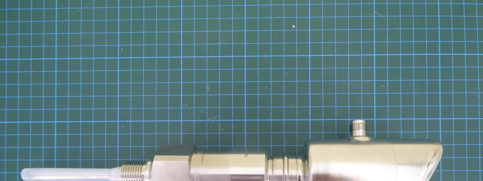
LCGFMI43
Jul 29, 2026Capacitive level sensor with BLE communication
Equipment Class
DTS - Digital Transmission System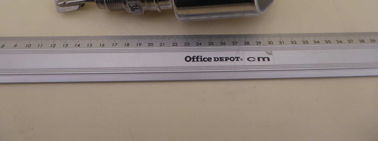
LCGFTL4X
Nov 28, 2024Hygienic point level switch for liquids with BLE TX
Equipment Class
DTS - Digital Transmission System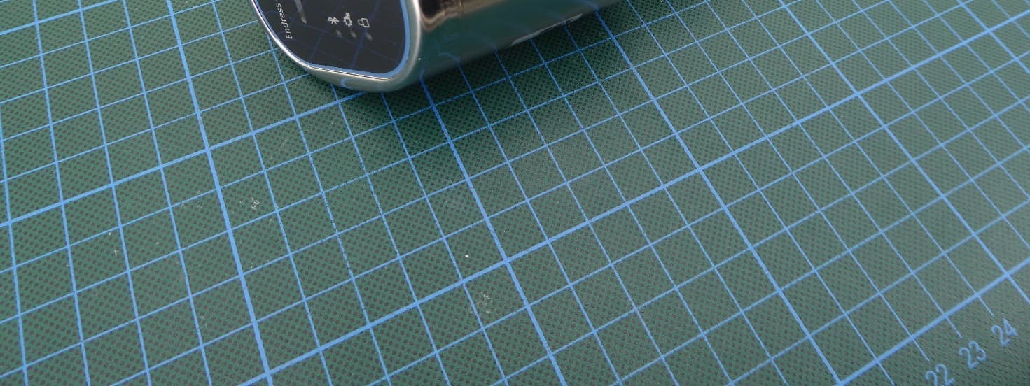
LCGFMR43L
Aug 07, 2024Level Probing Radar
Equipment Class
DXX - Part 15 Low Power Communication Device Transmitter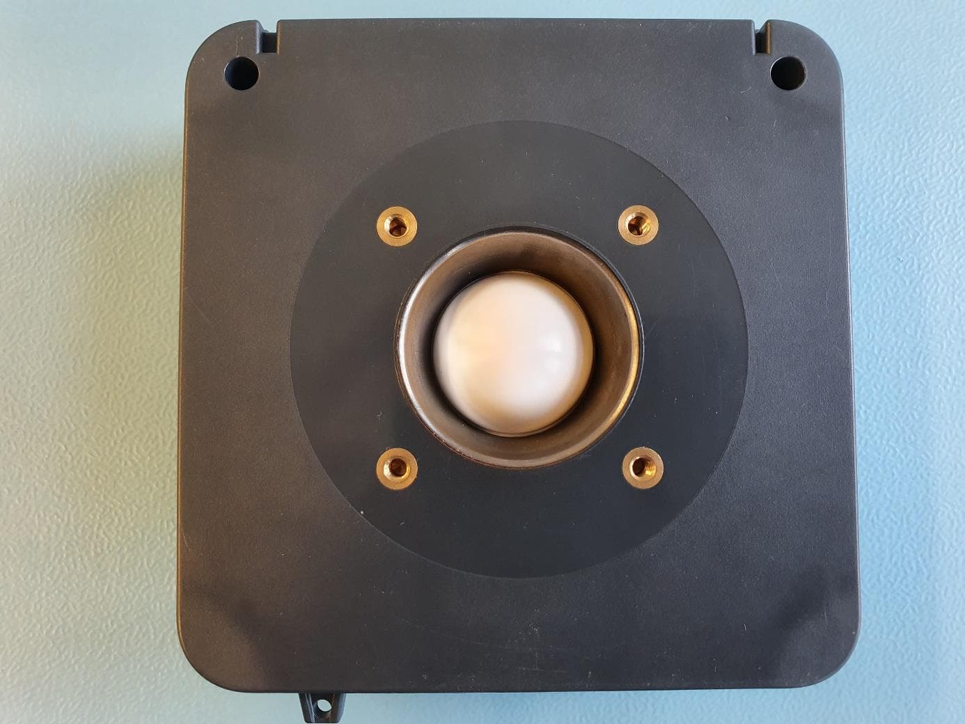
LCGFWR3XWEL
May 18, 2020Level Probing Radar
Equipment Class
LPR - Level Probing Radar
LCGVU113
Mar 11, 2020BTLE Display
Equipment Class
DTS - Digital Transmission System