LE2-CCD325CWOutdoor Wireless Camera
JSW Pacific Corporation
Click to zoom
Application Details
- Equipment Class
- DXX - Part 15 Low Power Communication Device Transmitter
- Date of Grant
- Dec 16, 2003
- Application Purpose
- Original Equipment
- Date of Application
- Dec 16, 2003
- Equipment Note
- Outdoor Wireless Camera
- Frequency Range
- 2412.00000000 - 2472.00000000
- Company
- JSW Pacific Corporation
- Country
- Taiwan
Documents & Files
Document Text
Text extracted from the exhibit documents filed with the FCC. Open a document above to read the original.
Users Manual
Model No.: CCD-325CW 2.4 GHz Wireless Color Weather-proof Camera Contents Important Safety Precautions ..................................1 Specifications ...........................................................2 .....................3 Installing Mounting Bracket .....................................3 Installing the Wireless Color Weather-proof C a m e r a . . . . . . . . . . . . . . . . . . . . . . . . . . . . . . . . . . 4 Troubleshooting Guide ............................................5 Warranty .....................................................................6 3 4 Parts Included with Camera - 2.4 GHz Single Channel Wireless Color Weather-proof Camera - Camera Stand - 10V AC/DC adaptor for the Camera Parts of The System Parts of the Camera 1. Camera lens 2.Antenna 3.Power Cable 4. Camera Stand 5. Camera Cover Shield Installation Tools you will need: Pencil, Drill, drill Bits, Phillips-head Screwdriver, Hammer Installing Mounting Bracket (Camera Stand) 1. Select a mouniting location. Use the mounting bracket as a guide and mark the screw holes with a pencile. 2. Drill 1/8" pilot holes over the center of each pencil mark. For mounting on drywall or sheet rock, use the wall anchors provided. Gently tap the anchors into the pilot holes with hammer until they are flush. 3. Align the bracket over the holes or wall anchors and tighten the screw to secure the bracket to the wall or ceiling. Installing the Wireless Color Weather-proof Camera To install the system, follow these steps: Weather-proof Camera: 1. Plug the AC/DC adapter cord into the power input jack on the bottom of power cable. 2. Water-proof camera power will auto on when you plug the AC/DC adapter into a standard (110V-240V) AC outlet. 3. Before system operated, the receiver channel should be selected the same channel as the channel sticker shown on the camera body. Wireless Camera Specification: Weather-proof camera: Image sensor 1/3'' Color CMOS IMAGE SENSOR Resolution 330 Horizontal TV Lines Lens 6mm Illumination 0.2 Lux Power Consumption 12V DC, 300mA 1.3 Watts Operating TEMP. 32' F - 122'F 0'C - 50'C Dimentions 100x95x40mm (approx) Channel Frequency Either 2412 or/ 2442 or/ 2472 16 Important Safety Precautions Please read before Installing Congratulations on your purchase of the 2.4GHz Wireless Color Weather-proof Camera . Please read these safety and operating instructions carefully before installing and using this system. - Keep the camera AC/DC adapter cords out of reach of children. - Do not place the camera, AC/DC adapter cords in a crib or playpen. - Locate the camera, AC/DC adapters where there is adequate ventilation. Do not locate the camera in direct sunlight. - Do not locate the camera, AC/DC adapters near heat sources such as heat registers, radiators, ovens, furnaces or other appliances with high operating temperatures. - Do not use with extension cords. Use only the AC/DC adapters provided with this system. ***Note: Use of other adapters may damage the units and void your warranty. - Only plug components into standard household voltage outlets (110V - 240V AC, 50Hz or 60 Hz). - Do not place cords from the AC/DC adapters and camera,where they can be pinched or stepped on. Protect the cords by keeping them out of the way of children, pets and routine household traffic. Do not place heavy objects on power cords or cover cords with rugs or carpet. - When cleaning, use a DRY, lint-free cloth. Unplug the camera, AC/DC adapters before cleaning. NEVER immerse any components in water and do not spray cleaners or solvents on the units. Doing so may damage the units or cause electrical shock. - Unplug the AC/DC adapters from the wall outlet when the system is not in use. - Mishandling, alterations or modifications not approved by the manufacturer will void the warranty. CAUTION! - Connect this unit ONLY to other compatible units. Do not connect it to any other type of alarm or auxiliary device. Connecting anything else to this unit may damage it or prevent it from operating properly. CAUTION! - Do not paint over the camera. CAUTION! - This system uses public airwaves for wireless operation. Images from other rooms near the camera may be broadcast and picked up. To protect your privacy, always turn off the camera when not in use. IMPORTANT! ACCESSORIES:Do not place weather-proof camera or equipment on an unstable cart, stand or table. The video monitor or equipment may fall causing serious injury to a child or adult, and serious damage to the equipment. Wall or shelf mounting should follow the manufacturer's instruction, and should use a mounting kit approved by the manufacturer. VENTILATION: Solts and openings in the cabinet and the back or bottom are provided for ventilation and to ensure reliable operation of the weather-proof camera or equipment and to protect if from overheating. These openings must not be blocked or covered. The openings should never be blocked by placing the weather-proof camera on a bed, sofa, rug, or other similar surface. Weather-proof camera should never be placed near or over a radiator or heat register. Weather-proof camera should not be placed in a built- in installation such as a bookcase unless proper ventilation is provided. You should... 1. Check that the power cord(s) for camera and receiver are properly connected. 2. Check that the monitor is turned ON. 3. Wrong AC/DC adapter used. Check if your are using the right AC/DC adapter. 1. Check the channel switch settings on the water-proof camera and receiver is the same channel. 2. Signal interference from a microwave oven. Check if a micro-wave oven is in use or located in the path between the weather-proof camera and receiver. If so, turn it off or move it out of the path. 3. Signal interference from other signal producing devices. (a) Identify and eliminate the source of the interference. (c) Relocate the weather-proof camera and/or receiver closer to each other. 4. Weather-proof Camera and receiver are too far apart. Relocate t…
Text truncated - open the document above for the full version.
External Photos
ETC Report No. : ET92R-10-110 FCC ID.: LE2-CCD325CW Rev. No 1.0 CONSTRUCTION PHOTOS OF EUT Front View of Transmitter Side View of Transmitter ETC Report No. : ET92R-10-110 FCC ID.: LE2-CCD325CW Rev. No 1.0 CONSTRUCTION PHOTOS OF EUT Side View of Transmitter Top View of Transmitter ETC Report No. : ET92R-10-110 FCC ID.: LE2-CCD325CW Rev. No 1.0 CONSTRUCTION PHOTOS OF EUT Rear View of Transmitter ETC Report No. : ET92R-10-110 FCC ID.: LE2-CCD325CW Rev. No 1.0 CONSTRUCTED PHOTOS of EUT Front View of Adaptor Rear View of Adaptor
Internal Photos
ETC Report No. : ET92R-10-110 FCC ID.: LE2-CCD325CW Rev. No 1.0 CONSTRUCTION PHOTOS OF EUT Internal View of Transmitter Front View of RF Module ETC Report No. : ET92R-10-110 FCC ID.: LE2-CCD325CW Rev. No 1.0 CONSTRUCTION PHOTOS OF EUT Rear View of RF Module Internal. View of RF Module ETC Report No. : ET92R-10-110 FCC ID.: LE2-CCD325CW Rev. No 1.0 CONSTRUCTION PHOTOS OF EUT Component View of RF Module PCB Solder View of RF Module PCB ETC Report No. : ET92R-10-110 FCC ID.: LE2-CCD325CW Rev. No 1.0 CONSTRUCTION PHOTOS OF EUT Component View of CCD PCB Solder View of CCD PCB ETC Report No. : ET92R-10-110 FCC ID.: LE2-CCD325CW Rev. No 1.0 CONSTRUCTED PHOTOS of EUT Internal View of Adaptor ETC Report No. : ET92R-10-110 FCC ID.: LE2-CCD325CW Rev. No 1.0 CONSTRUCTED PHOTOS of EUT Component View of Adaptor’s PCB Solder View of Adaptor’s PCB
Test Report
Rev. No 1.0 FCC Part 15 EMI TEST REPORT of E.U.T. : OUTDOOR WIRELESS CAMERA MODEL : CCD-325CW FCC ID. : LE2-CCD325CW for APPLICANT : JSW PACIFIC CORPORATION. ADDRESS : 7th fl, 168-1, Lien Cheng Rd, Chung Ho City, Taipei Hsien, Taiwan Test Performed by ELECTRONICS TESTING CENTER, TAIWAN NO. 34, LIN 5, DING FU TSUN, LINKOU HSIANG TAIPEI HSIEN, TAIWAN, R.O.C. Tel:(02)26023052, Fax:(02)26010910 Report Number : ET92R-10-110 ETC Report No. : ET92R-10-110 FCC ID. : LE2-CCD325CW Rev. No 1.0 TEST REPORT CERTIFICATION Applicant : JSW PACIFIC CORPORATION 7th fl, 168-1, Lien Cheng Rd, Chung Ho City, Taipei Hsien, Taiwan Manufacturer : JSW PACIFIC CORPORATION 7th fl, 168-1, Lien Cheng Rd, Chung Ho City, Taipei Hsien, Taiwan Description of EUT : a) Type of EUT : OUTDOOR WIRELESS CAMERA b) Trade Name : Navigator c) Model No. : CCD-325CW d) Power Supply : Adaptor: I/P: AC110V, 60Hz ; O/P: DC 9V, 200mA e) Working Frequency : 2400MHz~2483.5MHz Regulation Applied : FCC Rules and Regulations Part 15 Subpart C (2002) I HEREBY CERTIFY THAT: The data shown in this report were made in accordance with the procedures given in ANSI C63.4, and the energy emitted by the device was founded to be within the limits applicable. I assume full responsibility for accuracy and completeness of these data. Note: 1. The result of the testing report relate only to the item tested. 2. The testing report shall not be reproduced expect in full, without the written approval of ETC. Issued Date : Nov. 25, 2003 Test Engineer : ( Tien Lu Liao ) Approve & Authorized Signer : Will Yauo, Manager EMC Dept. II of ELECTRONICS TESTING CENTER, TAIWAN ETC Report No. : ET92R-10-110 FCC ID. : LE2-CCD325CW Rev. No 1.0 Table of Contents Page 1 GENERAL INFORMATION.......................................................................................................1 1.1 Product Description...................................................................................................................1 1.2 Characteristics of Device..........................................................................................................1 1.3 Test Methodology......................................................................................................................1 1.4 Test Facility................................................................................................................................1 2 PROVISIONS APPLICABLE.......................................................................................................2 2.1 Definition....................................................................................................................................2 2.2 Requirement for Compliance....................................................................................................3 2.3 Restricted Bands of Operation..................................................................................................5 2.4 Labeling Requirement................................................................................................................5 2.5 User Information........................................................................................................................6 3. SYSTEM TEST CONFIGURATION...........................................................................................7 3.1 Justification................................................................................................................................7 3.2 Devices for Tested System........................................................................................................7 4 RADIATED EMISSION MEASUREMENT..............................................................................8 4.1 Applicable Standard....................................................................................................................8 4.2 Measurement Procedure...........................................................................................................8 4.3 Measuring Instrument..............................................................................................................10 4.4 Radiated Emission Data...........................................................................................................11 4.4.1 RF Portion...............................................................................................................................11 4.4.2 Other Emission........................................................................................................................14 4.5 Field Strength Calculation.......................................................................................................14 4.6 Photos of Radiation Measuring Setup....................................................................................15 5 CONDUCTED EMISSION MEASUREMENT........................................................................16 5.1 Standard Applicable..................................................................................................................16 5.2 Measurement Procedure.........................................................................................................16 5.3 Conducted Emission Data.......................................................................................................17 5.5 Conducted Measurement Equipment......................................................................................19 5.6 Photos of Conduction Measuring Setup................................................................................20 6 ANTENNA REQUIREMENT....................................................................................................21 6.1 Standard Applicable..................................................................................................................21 6.2 Antenna Construction..............................................................................................................21 7 BA…
Text truncated - open the document above for the full version.
Test Setup Photos
ETC Report No. : ET92R-10-110 FCC ID.: LE2-CCD325CW Rev. No 1.0 Photos of Radiation Measuring Setup ETC Report No. : ET92R-10-110 FCC ID.: LE2-CCD325CW Rev. No 1.0 Photos of Conduction Measuring Setup
Contact Information
Applicant
Min Hui Chen(Vice President)
Test Firm
Electronics Testing Center, TaiwanWin-Po Tsai
Technical Specifications
| # | Rule Parts | Frequency Range | Power Output |
|---|---|---|---|
| 1 | 15C | 2.41 GHz - 2.47 GHz | - |
Other Applications from JSW Pacific Corporation
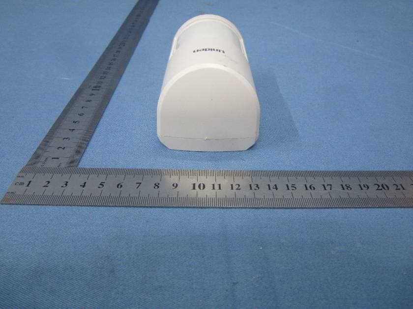
LE2PIR31
Nov 21, 2015Wireless portable / wall-mount area motion alert sensor
Equipment Class
DXX - Part 15 Low Power Communication Device Transmitter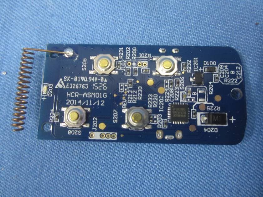
LE2RC41
Nov 21, 2015Wireless multi-functional panic remote controller
Equipment Class
DXX - Part 15 Low Power Communication Device Transmitter
LE2APPCAM26PTA
Jun 13, 2015720p PT WIFI Camera
Equipment Class
DTS - Digital Transmission System
LE2APPCAM25HDA
May 25, 2015720p WIFI Camera
Equipment Class
DTS - Digital Transmission System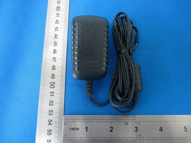
LE2APPCAM24HD
May 24, 2015720p WIFI Camera
Equipment Class
DTS - Digital Transmission System