LE2CCD-625SCCD-625 Wireless Color Monitoring System
JSW Pacific Corporation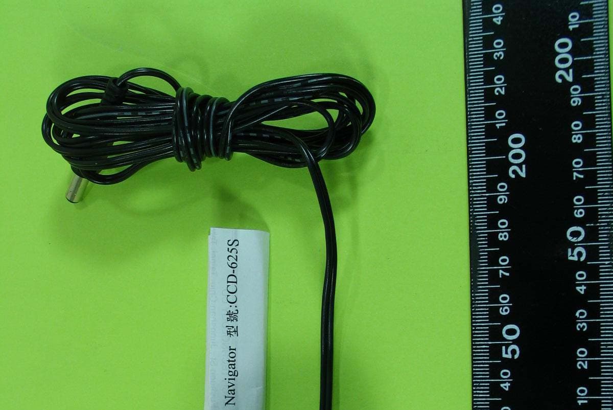
Click to zoom
Application Details
- Equipment Class
- DXX - Part 15 Low Power Communication Device Transmitter
- Date of Grant
- Aug 11, 2004
- Application Purpose
- Original Equipment
- Date of Application
- Aug 11, 2004
- Equipment Note
- CCD-625 Wireless Color Monitoring System
- Frequency Range
- 2412.00000000 - 2472.00000000
- Company
- JSW Pacific Corporation
- Country
- Taiwan
Documents & Files
Document Text
Text extracted from the exhibit documents filed with the FCC. Open a document above to read the original.
Users Manual
Model No.: CCD-625 2.4 GHz Wireless Color 2.5" TFT Monitoring System Contents Important Safety Precautions ..................................1 Specifications ............................................................2 Parts Included with This System .............................3 Parts of the Wireless Monitoring System ...............3 - Parts of the Camera ...............................................3 - Parts of the Monitor ................................................3 Installation .................................................................4 - Installing the Mounting Bracket (Camera Stand) .....................................................4 - Installing and Aligning the Camera on t he Mounting B racket ( Camera S tand) . ............4 - Installing or Replacing Batteries in the Camera .....4 - Installing the Wireless Monitoring System .............5 Rotating the Antenna for Best Performance .........6 Monitor to A/V Function ............................................6 Troubleshooting Guide .............................................7 Warranty .....................................................................7 You should... 1. Check that the power cord(s) is properly connected. 2. Check that the monitor is turned ON. 3. Wrong AC/DC adapter used. Check that the adapter labeled OUTPUT: 10V DC is connected to the camera, and adapter labeled OUTPUT: 5V DC is connected to the monitor. 1. Check the channel switch settings on the camera(s) and monitor. Make sure the channels match on both units. 2. Signal interference from a microwave oven. Check if a micro-wave oven is in use or located in the path between the camera and monitor. If so, turn it off or move it out of the path. 3. Signal interference from other signal producing devices. (a) Change the channel setting on both camera and monitor. (b) Identify and eliminate the source of the interference. (c) Relocate the camera and/or monitor closer to each other. 4. Camera and monitor are too far apart. Relocate the camera and/or monitor 5. Antenna is positioned improperly. Adjust the antenna on the camera and/or monitor. Troubleshooting Guide If the Camera and/or Monitor... No Power No sound or picture. Distorted sound or picture 7 1 Year Limited Warranty: JSW Pacific Corp., the maker of Navigator“ brand products, warrants that for a period of 1 year from the date of purchase, this product will be free from defects in material and workmanship. JSW, at its option, will repair or replace this product or any component of the product found to be defective during the warranty period. Replacement will be made with a new or remanufactured product or component. If the product is no longer available, replacement may be made with a similar product of equal or greater value. This is your exclusive warranty. This warranty is valid for the original purchaser from the date of initial purchase with JSW and is not transferable. This warranty does not cover normal wear of parts or damage resulting from any of the following: negligent use or misuse of the product, use on improper voltage or current, use contrary to the operating instructions, disassembly, repair or alteration by anyone other than JSW or an authorized service center. Further, the warranty does not cover acts of God, such as fire, flood, hurricanes and tornadoes or any batteries that are included with this unit. JSW shall not be liable for any incidental or consequential damages caused by the breach of any express or implied warranty.
Users Manual
16 Rotating the Antenna for Best Performance This system broadcasts its high-quality audio and video using directional antenna. The antenna can rotate in either clockwise or counterclockwise directions to obtain the best signal and picture clarity. IMPORTANT! See the instructions shown below to rotate the antenna. Rotating the antennas beyond the specified range will result in permanent damage to both antenna and the mechanical stop. The camera's antenna will NOT rotate 360 degrees. In most situations, the flat pitted face of the antenna on both the camera should be facing the monitor. Since all rooms are different, additional adjusting of the antenna may be necessary to get optimal performance. If the camera and monitor are less than 10 feet apart, leave the antenna in the closed (down) position. See the instructions shown on the right to rotate the antenna. Important Safety Precautions Please read before Installing Congratulations on your purchase of the 2.4GHz Wireless Monitoring System. Please read these safety and operating instructions carefully before installing and using this system. - Keep the camera, monitor and AC/DC adapter cord out of reach of children. - Do not place the camera, monitor or AC/DC adapter cord in a crib or playpen. - Do not use the camera near water or damp and wet environments, such as a bathtub, laundry tub, kitchen sink, or wet basements. - Locate the camera, monitor and AC/DC adapter where there is adequate ventilation. Do not locate the camera in direct sunlight. - Do not locate the camera, monitor and AC/DC adapter near heat sources such as heat registers, radiators, ovens, furnaces or other appliances with high operating temperatures. - Do not use with extension cords. Use only the AC/DC adapter provided with this system. Use of other adapters may damage the camera or monitor and void your warranty. - Only plug components into standard household voltage outlets (110V - 240V AC, 50Hz or 60 Hz). - Do not place cords from the AC/DC adapters, camera or monitor where they can be pinched or stepped on. Protect the cords by keeping them out of the way of children, pets and routine household traffic. Do not place heavy objects on power cords or cover cords with rugs or carpet. - When cleaning, use a DRY, lint-free cloth. Unplug the camera, monitor and AC/DC adapter before cleaning. NEVER immerse any components in water and do not spray cleaners or solvents on the unit. Doing so may damage the unit or cause electrical shock. - Unplug the AC/DC adapter from the wall outlet when the system is not in use. - Mishandling, alterations or modifications not approved by the manufacturer will void the warranty. CAUTION! - Connect this unit ONLY to other compatible units. Do not connect it to any other type of alarm or auxiliary device. Connecting anything else to this unit may damage it or prevent it from operating properly. CAUTION! - Do not paint over the camera. CAUTION! - This system uses public airwaves for wireless operation. The sound and video may be broadcast to and picked up by other 2.4 GHz receiving devices. Conversations and images from other rooms near the camera may be broadcast and picked up. To protect your privacy, always turn the camera off when not in use. IMPORTANT! ACCESSORIES- Do not place video monitor or equipment on an unstable cart, stand or table. The video monitor or equipment may fall causing serious injury to a child or adult, and serious damage to the equipment. Wall or shelf mounting should follow the manufacturer's instruction, and should use a mounting kit approved by the manufacturer. Video monitor equipment and cart combinations should be moved with care. Quick stops, excessive force, and uneven surfaces may cause the equipment and cart combination to overturn. VENTILATION- Slots and openings in the cabinet and the back or bottom are provided for ventilation and to ensure reliable operation of the video monitor or equipment and to protect it from overheating. These openings must not be blocked or covered. The openings should never be blocked by placing the video monitor on a bed, sofa, rug, or other similar surface. Video monitor or equipment receiver should never be placed near or over a radiator or heat register. Video monitor or equipment receiver should not be placed in a built-in installation such as a bookcase unless proper ventilation is provided. Up/Down 84 º Rotate Clockwise/270º Counterclockwise Monitor to A/V Function The monitor has audio/video outputs which can be used to transfer the picture and sound from the monitor screen to a TV screen. Connect the A/V outputs to the A/V input on a TV set for a large screen display, or connect the A/V outputs to the A/V inputs on a VCR to record transmissions from the camera.
Users Manual
User's Manual Model No.: CCD-625 - Portable 2.5" Color TFT LCD with Receiver - Camera with Patch Antenna PLEASE READ CAREFULLY AND SAVE This manual contains important information about this product's operation. If you are installing this product for use by others you must leave this manual -or a copy- with the end user. Navigator R
Users Manual
52 Installing the Wireless Monitoring System When installing the camera, check the reception of the monitor before final installation. Have someone to hold the camera in the area to be monitored. Have another person move the monitor to a variety of locations throughout the house to check reception. If interference or other problems occur, refer to the Troubleshooting Guide. To install the system, follow these steps: Camera: 1. Plug the 10V AC/DC adapter cord into the DC Input Jack on the back of the camera. 2. Plug the adapter into a standard (110V-240V) AC outlet. Push the Power ON/OFF switch to ON position. The power indicator LED should light. 3. Or use battery for power supply (The life time for 4 pcs "AA" size battery operation is 45 minutes) Monitor: 1. Plug the 5V AC/DC adapter cord into the DC Input Jack on the side of the monitor. 2. Plug the adapter into a standard (110V-240V) AC outlet. Press the power button to turn on the monitor. 3. A/V outputs on the LCD monitor can be connected to the A/V input on a TV set for a large screen display, or to the A/V inputs on a VCR for recording. 4. A/V inputs on the LCD monitor can be directly connected to the camera with A/V cable (included in the package), or connect to the A/V output on a VCR for watching video on the monitor. 5. You can use either AC/DC adapter for long time use or 4 AA" battery for mobile use. The life time of 4 AA" battery operation is 45 minutes. System Installation: 1. Select the channel (Channel 1-4) to be used on both the camera and monitor. NOTE: Make sure the camera and monitor are set to the same channel (1, 2, 3 or 4). 2. Set the selected channel by gently pushing the dip-switch for that channel to the ON position on the camera. For example, to set both the camera and monitor on Channel 1: (a) Push the Channel 1 dip-switch located on the back of the camera and the front of the monitor to the ON position. (b) Make sure the remaining dip-switches are in the OFF position. In this case, channels 2, 3 and 4 should be in the OFF position. (c) Press the Channel Slection Key on the monitor to select Channel. 3. Position the camera angle for best view of monitored area. 4. Position the camera antenna toward the monitor antenna. Rotate/adjust the antennas on both the camera and monitor for best performance. 5. Adjust the Volume Control on the side of the monitor to desired level. 6. Adjust the Brightness by using Brightness Control on the side of the monitor. ON 1 2 3 4 Specifications MONITOR: SCREEN SIZE 2.5" TFT LCD DOT PITCH 0.1025 x 0.163mm RESOLUTION 480 x 234 POWER SUPPLY 5V DC, 1.5A OPERATING TEMP. 32°F - 122°F 0°C - 50°C Screen Size 2.45 Diagonal Inch BATTERY 4 "AA" Size Batteries (Last for 45 minutes, Batteries Not Included) AUDIO OUTPUT 600 ohms / 1V p-p Active Area 49.2 x 38.142 mm CAMERA: IMAGE SENSOR 1/3" Color CMOS Image Sensor RESOLUTION 300 Horizontal TV Lines LENS 6mm ILLUMINATION O Lux with IR up to 10 feet POWER 10V DC, 600 mA CONSUMPTION 1.3 Watts OPERATING TEMP. 32°F - 122°F 0°C - 50°C WEIGHT Approx. 0.46LB/206g BATTERY 4 "AA" Size Batteries (Last for 45 minutes, Batteries Not Included) DIMENSIONS Approx. 4.5" x 2.8" x 2.4" 11.4 x 7.3 x 6cm (LxWxH) FCC/CE WARNING This equipment generates and uses radio frequency energy and if not installed and used properly, that is, in strict accordance with the manufacture's instructions, may cause interference to radio and television reception. It has been tested and found to comply with limits for a Class B digital device in accordance with Part 15 of FCC Rules and CE I-ETS 300 440, which are designed to provide reasonable protection against such interference in a residential installation. However, there is no guarantee that interference will not occur in a particular installation. If this equipment does cause interference to radio or television reception, which can be determined by turning the equipment off and on, the user is encouraged to try to correct the interference by one or more of the following measures: 1. Reorient the TV/radio antenna. 2. Relocate the Receiver away from the TV/radio receiver. 3. Plug the Receiver into a different wall outlet so that the Receiver is on a different branch circuit. 4. If necessary, the user should consult the dealer or an experienced radio/television technician for additional suggestions. The user may find the following booklet prepared by the Federal Communication Commission helpful: "How to Identify and Resolve TV Interference Problems." This booklet is available from the US Government Printing Office, Washington, D.C. 20402, Stock No. 004-000-00345-4. FCC/CE NOTICE The user is cautioned that changes or modifications not expressly approved by the manufacturer could void the user's authority to operate the equipment. Linear radio controls provide a reliable communications link and fill an important need in portable wireless signaling. However, there are some limitations which must be observed. The radios are required to comply with FCC Rules and Regulations as Part 15 devices and CE I-ETS 300 440. As such, they have limited transmitter power and therefore limited range. A receiver cannot respond to more than one transmitted signal at a time and may be blocked by radio signals that occur on or near their operating frequencies. Changes or modifications to the device may void FCC and CE compliance. Infrequently used radio links should be tested regularly to protect against undetected interference or fault.
Users Manual
Important! Please read this booklet carefully before installing or using these units. DANGER- HIGH VOLTAGE- These units should ONLY be opened by an authorized technician if service is required. Safety Precautions For correct and safe operation of this system, it is essential that installers, end- users and service technicians should follow all safety procedures outlined in this manual. Specific Warning and Caution statements (and/or symbols) are marked on the units where needed. Warning and Caution Statements "WARNING" indicates a situation where failure to follow proper procedures can cause personal injury. "CAUTION" indicates a situation where failure to follow proper procedures can cause damage to the equipment.
Users Manual
34 Parts Included with This System - Camera with Built-In Transmitter - 5V AC/DC Adapter for the Monitor - 2.5"Color TFT LCD Monitor with Built-In 2.4 GHz Receiver - Camera Stand - 10V AC/DC Adapter for the Camera - 1.5m A/V Cable Parts of the Wireless Monitoring System Installation Tools you will need: Pencil, Drill, Drill Bits, Phillips-head Screwdriver, Hammer Installing Mounting Brackets for Camera 1. Select a mounting location. Use the mounting bracket as a guide and mark the screw holes with a pencil. 2. Drill 1/8" pilot holes over the center of each pencil mark. For mounting on drywall or sheet rock, use the wall anchors provided. Gently tap the anchors into the pilot holes with hammer until they are flush. 3. Align the bracket over the holes or wall anchors and tighten the screws to secure the bracket to the wall or ceiling. Installing and Aligning the Camera on the Mounting Bracket (Camera Stand) 1. Remove camera platform and ball joint from the mounting bracket adjustment collar. 2. Secure the camera to the camera platform on the adjustment collar. Hand tighten the screw to the threaded insert located in the base of the camera. 3. For battery operation, insert batteries as detailed below. 4. Secure the camera, camera platform, and ball joint to the mounting bracket until tight. 5. Adjust the camera. Rotate the ball joint and/or collar slot while tightening to align the lens in the direction of preferred sight. 6. If the unit was shipped with a black lens cap, remove it. Installing or Replacing Batteries in the Camera IMPORTANT! When installing or replacing batteries: 1. Do not mix old and new batteries. Replace all the batteries at the same time. 2. Do not mix alkaline, standard and rechargeable batteries. Use one type of battery. 3. When storing the units or during long periods of non use, remove the batteries. Failure to remove the batteries may damage the unit. The camera uses 4 "AA” size (R6) batteries to operate on battery power. To install/replace batteries: 1. Remove the battery cover by pushing the lock area marked "OPEN". 2. Insert (or remove) 4 "AA" size batteries. NOTE: Install batteries using the polarity markings (+ and -) in the battery compartment. Attach Stand to Mounting Surface Camera Stand Attach Stand to Camera DC In Channel Switch Antenna Night Vision LED Power Switch Battery Compartment (At Bottom) Power LED Camera Lens Rear View
Cover Letter(s)
Central Research Technology CO. No.11, Lane 41, Fushun St., Taipei, Taiwan, 104 , R.O.C. Tel.:886-2-2598 4568 Fax:886-2-2598 4546 August 4, 2004 RE: JSW Pacific Corporation FCC ID: LE2CCD-625S Answers to ATCB comments: Q1.:There are a number of Exhibits missing from this filing. Please supply a completed Form 731. Please supply all items listed in 47CFR 2.1033(b) including proposed Label, Manual, and Operational Description. Please note that for any Unlicensed Part 15C transmitters a Parts List is never required. A1.: Per your request, 731 form, label sample & location, user manual, and Operational Description (revised) are all uploaded. Please refer to those exhibits. Q2.:Please supply an Agent Authorization letter on the Applicant letterhead allowing CRC to act as agent on behalf of JSW Pacific Corporation. A2.: Uploaded, please refer to “(CD-625S)POA.pdf” exhibit. Q3.:There is no Confidentiality request letter. If the Schematics and Block Diagram are considered proprietary, a Confidentiality Request letter is required. A3.: Uploaded, please refer to “(CCD-625S)Confidentiality Request.pdf” exhibit. Please note that “all documents loaded are requested as permanent confidentiality”. Q4.:Please refer to 2.1033(b)(5) – there appear to be several oscillators with frequencies that are not shown. Please provide a properly annotated Block Diagram. A4.:Please refer to “(LE2CCD-625S)Block diagram(revised).jpg” exhibit. Q5.:FYI: Please note that MPE evaluations are only required for selected devices under Part 15. You do not have to provide MPE estimations for 15.249 and in fact this report will not be uploaded to the Commission. A5:Noted, thanks for your info. Q6.:Your photographs are of good quality, but do not meet the legal definitions of 2.1033(b)(7). Please provide larger photographs – preferably only one to a page. A6.:Please refer to “LE2CCD-625S)ExtPho(revised).doc” and “(LE2CCD-625S)IntPho(revised).doc” exhibits. Q7.:The Test Setup photos are difficult to resolve. It is necessary for me to be certain that all peripherals are attached and fully exercised during testing. Kindly provide larger Test Setup photos. A7:Please refer to “(LE2CCD-625S)Test Setup Photos(revised).doc” exhibit. Q8.:FYI: Receivers that operate above 960MHz are only subject to DofC or Certification. For clarity, this 15.249 Test Report should only address the Transmitter and not the Receiver. Kindly refer to 15.101. A8.:Noted, thanks for your info. Q9.:The test results in section 3.6 of the Test Report show an emission reading of approximately 77.9dBuV peak and 77.7dBuV average. This is certainly a passing test result. However, I am not able to correlate these readings to the radiated Band Edge test of section 4.4. The Commission is very concerned with radiated spurious emissions intruding into the Restricted Bands of 15.205. Please provide properly annotated spectrum plots showing start frequency, stop frequency, resolution bandwidth, video bandwidth, sweep time, scale in dB/division, and peak radiated value of the fundamental. A9.:Please refer to “(LE2CCD-625S)Band Edge Test.doc” exhibit for more details. Q10.:It is unclear how the antenna is affixed to the transmitter. Please describe how the requirements of 15.204(c) are met. A10:Please refer to “(LE2CCD-625S)Description about how the antenna is affixed.doc” exhibit for more info. Q11.:FYI: Please be sure any Manual submitted in conjunction with this filing meets the requirements of 15.19(a) and 15.21. Alternative labeling of the device may be required depending on the final form of the Manual. Please note that if this product is capable of interfacing directly to the antenna terminals of a television broadcast receiver and meets the strict interpretation of a “TV Interface Device”, then additional requirements could apply. See 15.115. A11.:Noted, thanks for your info. Date loaded: August 12, 2004 Reviewer:William H. Graff / President and Director of Engineering mailto: [email protected]
Cover Letter(s)
JSW PACIFIC CORPORATION NAVIGATOR ® TEL: +886-2-8227-8582 FAX: +886-2-8227-8583 ADD: 3F-3, No 700, Chung Zheng Rd., Chung Ho City, Taipei Hsien, Taiwan Website: www.jsw.com.tw ; www.globalsources.com/jsw.co e-mail: [email protected] Letter Of Agency Authorization August 5, 2004 American Telecommunications Certification Body, Inc. 6731 Whittier Avenue Suite C110 McLean, VA 22101 To Whom It May Concern: Please be advised that JSW Pacific Corporation authorizes Central Research Technology Co. to act as on our behalf, until otherwise notified, for applications submitted to American Telecommunications Certification Body, Inc. (ATCB). We certify that we are not subject to denial of federal benefits, that includes FCC benefits, pursuant to Section 5301 of the Anti-Drug Abuse ACT of 1988, U.S.C. 862. Further, no party, as defined in 47 CFR 1.2002(b), to the application is subject to denial of federal benefits, that includes FCC benefits. Thank you for your attention to this matter. _________________________________________ Joe Hsu Director / CEO office JSW PACIFIC CORPORATION
Cover Letter(s)
CENTRAL RESEARCH TECHNOLOGY CO. No. 11, Lane 41, Fushuen St., Jungshan Chiu, Taipei, Taiwan, 104, R.O.C. Page : TEL. : 886-2-25984542 FAX. : 886-2-25984546 1 The antenna is soldered with RF model, so the use of a permanently attached antenna, and its relative information as follow: Brand Model Frequency Range (MHz) Gain (dBi) Comment N/A N/A 2402~2480 1.2 Antenna Position:
Cover Letter(s)
FCC ID: LE2CCD-625S JSW PACIFIC CORPORATION 3F-3, No 700, Chung Zheng Rd., Chung Ho City, Taipei Hsien, Taiwan TEL:86-2-8227-8582 FAX: 886-2-8227-8583 Federal Communications Commission Authorization and Evaluation Division Confidentiality Request Pursuant to Sections 0.457 and 0.459 of the Commission’s Rules, the Applicant hereby requests confidential treatment of information accompanying this Application as outlined below: Schematics block diagram (permanent confidentiality) The above materials contain trade secrets and proprietary information not customarily released to the public. The public disclosure of these matters might be harmful to the Applicant and provide unjustified benefits to its competitors. The Applicant understands that pursuant to Rule 0.457, disclosure of this Application and all accompanying documentation will not be made before the date of the Grant for this application. Sincerely, _____________________________ Joe Hsu Director / CEO office JSW PACIFIC CORPORATION
External Photos
FCC Test Report Report No.:RF-A63-0406-055 CENTRAL RESEARCH TECHNOLOGY CO. Page : A2-1 No. 11, Lane 41, Fushuen St., Jungshan Chiu, Taipei, Taiwan, 104, R.O.C. TEL. : 886-2-25984542 FAX. : 886-2-25984546 Attachment 2 External Photographs of EUT FCC Test Report Report No.:RF-A63-0406-055 CENTRAL RESEARCH TECHNOLOGY CO. Page : A2-1 No. 11, Lane 41, Fushuen St., Jungshan Chiu, Taipei, Taiwan, 104, R.O.C. TEL. : 886-2-25984542 FAX. : 886-2-25984546 FCC Test Report Report No.:RF-A63-0406-055 CENTRAL RESEARCH TECHNOLOGY CO. Page : A2-2 No. 11, Lane 41, Fushuen St., Jungshan Chiu, Taipei, Taiwan, 104, R.O.C. TEL. : 886-2-25984542 FAX. : 886-2-25984546 FCC Test Report Report No.:RF-A63-0406-055 CENTRAL RESEARCH TECHNOLOGY CO. Page : A2-3 No. 11, Lane 41, Fushuen St., Jungshan Chiu, Taipei, Taiwan, 104, R.O.C. TEL. : 886-2-25984542 FAX. : 886-2-25984546 FCC Test Report Report No.:RF-A63-0406-055 CENTRAL RESEARCH TECHNOLOGY CO. Page : A2-4 No. 11, Lane 41, Fushuen St., Jungshan Chiu, Taipei, Taiwan, 104, R.O.C. TEL. : 886-2-25984542 FAX. : 886-2-25984546 FCC Test Report Report No.:RF-A63-0406-055 CENTRAL RESEARCH TECHNOLOGY CO. Page : A2-5 No. 11, Lane 41, Fushuen St., Jungshan Chiu, Taipei, Taiwan, 104, R.O.C. TEL. : 886-2-25984542 FAX. : 886-2-25984546 FCC Test Report Report No.:RF-A63-0406-055 CENTRAL RESEARCH TECHNOLOGY CO. Page : A2-6 No. 11, Lane 41, Fushuen St., Jungshan Chiu, Taipei, Taiwan, 104, R.O.C. TEL. : 886-2-25984542 FAX. : 886-2-25984546 FCC Test Report Report No.:RF-A63-0406-055 CENTRAL RESEARCH TECHNOLOGY CO. Page : A2-7 No. 11, Lane 41, Fushuen St., Jungshan Chiu, Taipei, Taiwan, 104, R.O.C. TEL. : 886-2-25984542 FAX. : 886-2-25984546 FCC Test Report Report No.:RF-A63-0406-055 CENTRAL RESEARCH TECHNOLOGY CO. Page : A2-8 No. 11, Lane 41, Fushuen St., Jungshan Chiu, Taipei, Taiwan, 104, R.O.C. TEL. : 886-2-25984542 FAX. : 886-2-25984546 FCC Test Report Report No.:RF-A63-0406-055 CENTRAL RESEARCH TECHNOLOGY CO. Page : A2-9 No. 11, Lane 41, Fushuen St., Jungshan Chiu, Taipei, Taiwan, 104, R.O.C. TEL. : 886-2-25984542 FAX. : 886-2-25984546 FCC Test Report Report No.:RF-A63-0406-055 CENTRAL RESEARCH TECHNOLOGY CO. Page : A2-10 No. 11, Lane 41, Fushuen St., Jungshan Chiu, Taipei, Taiwan, 104, R.O.C. TEL. : 886-2-25984542 FAX. : 886-2-25984546
ID Label/Location Info
20 mm 10 mm FCC ID : LE2CCD-625S This device complies with Part 15 of the FCC Rules. Operation is subject to the following two conditions: (1) This device may not cause harmful interference, and (2) This device must accept any interference received, including interference that may cause undesired operation.
Internal Photos
FCC Test Report Report No.:RF-A63-0406-055 CENTRAL RESEARCH TECHNOLOGY CO. No. 11, Lane 41, Fushuen St., Jungshan Chiu, Taipei, Taiwan, 104, R.O.C. Page : A3- TEL. : 886-2-25984542 FAX. : 886-2-25984546 1 Attachment 3 Internal Photographs of EUT FCC Test Report Report No.:RF-A63-0406-055 CENTRAL RESEARCH TECHNOLOGY CO. No. 11, Lane 41, Fushuen St., Jungshan Chiu, Taipei, Taiwan, 104, R.O.C. Page : A3- TEL. : 886-2-25984542 FAX. : 886-2-25984546 2 FCC Test Report Report No.:RF-A63-0406-055 CENTRAL RESEARCH TECHNOLOGY CO. No. 11, Lane 41, Fushuen St., Jungshan Chiu, Taipei, Taiwan, 104, R.O.C. Page : A3- TEL. : 886-2-25984542 FAX. : 886-2-25984546 3 FCC Test Report Report No.:RF-A63-0406-055 CENTRAL RESEARCH TECHNOLOGY CO. No. 11, Lane 41, Fushuen St., Jungshan Chiu, Taipei, Taiwan, 104, R.O.C. Page : A3- TEL. : 886-2-25984542 FAX. : 886-2-25984546 4 FCC Test Report Report No.:RF-A63-0406-055 CENTRAL RESEARCH TECHNOLOGY CO. No. 11, Lane 41, Fushuen St., Jungshan Chiu, Taipei, Taiwan, 104, R.O.C. Page : A3- TEL. : 886-2-25984542 FAX. : 886-2-25984546 5
Operational Description
Operational Description The operational description of model no.:CCD-625S This device is a 2.4GHz AV sender and the operational description is as follows: 1. The base band signals, video and audio, are picked up by the CCD and MIC respectively, and then are fed into the modulation circuit. 2. The frequency transmitted is generated by LO circuit and controlled by the PLL circuit. This frequency then is modulated with the base band signals. 3. With the power amplifier, the frequency is fed into the antenna and then is transmitted out to the relevant receiver for receiving and demodulating the base bad signals.
Test Report
FCC Test Report Report No.:RF-A63-0406-055 CENTRAL RESEARCH TECHNOLOGY CO. Page : 1 No. 11, Lane 41, Fushuen St., Jungshan Chiu, Taipei, Taiwan, 104, R.O.C. TEL. : 886-2-25984542 FAX. : 886-2-25984546 FCC Test Report for Wireless Color 2.5" TFT Monitoring System Trade Name : Navigator Model Number : CCD-625S FCC ID : LE2CCD-625S Report Number : RF-A63-0406-055 Date of Receipt : June 11,2004 Date of Report : June 16,2004 Prepared for JSW PACIFIC CORPORATION 3F-3, No. 700, Chung-Zheng Rd., Chung Ho City, Taipei Hsien, Taiwan, R.O.C. Prepared by Central Research Technology Co. EMC Test Laboratory No.11, Lane41, Fushuen St., Jungshan Chiu, Taipei, Taiwan, 104, R.O.C. NVLAP LAB CODE 200575-0 This report shall not be reproduced, except in full, without the written approval of Central Research Technology Co.. It may be duplicated completely in its entirely for legal use with the permission of the applicant. It should not be used to claim product endorsement by CNLA, NVLAP or any U.S. government agency. The test result in the report applies only to the sample tested. Total : 113 Pages 0905 ILAC MRA FCC Test Report Report No.:RF-A63-0406-055 CENTRAL RESEARCH TECHNOLOGY CO. Page : 2 No. 11, Lane 41, Fushuen St., Jungshan Chiu, Taipei, Taiwan, 104, R.O.C. TEL. : 886-2-25984542 FAX. : 886-2-25984546 Certification of Compliance Equipment under Test : Wireless Color 2.5" TFT Monitoring System Model No. : CCD-625S FCC ID : LE2CCD-625S Applicant : JSW PACIFIC CORPORATION Address : 3F-3, No. 700, Chung-Zheng Rd., Chung Ho City, Taipei Hsien, Taiwan, R.O.C. Applicable Standards : 47 CFR part 15, Subpart C Date of Testing : June 14 ~ June 15, 2004 Deviation : N/A Condition of Test Sample : Prototype We, Central Research Technology Co., hereby certify that one sample of the designated product was tested in our facility during the period mentioned above. The test records, data evaluation and Equipment Under Test (EUT) configurations shown in the present report are true and accurate representation of the measurements of the sample’s RF characteristics…
Text truncated - open the document above for the full version.
Contact Information
Applicant
Min Hui Chen(Vice President)
Technical Contact
Central Research Technology Co.Sam Chien
[email protected]+886 2 2598 4568
No. 11, Lane 41, Fushun St. · Taipei City · Taiwan
Test Firm
Central Research Technology Co.Tsun-Yu Shih
Technical Specifications
| # | Rule Parts | Frequency Range | Power Output |
|---|---|---|---|
| 1 | 15C | 2.41 GHz - 2.47 GHz | - |
Other Applications from JSW Pacific Corporation
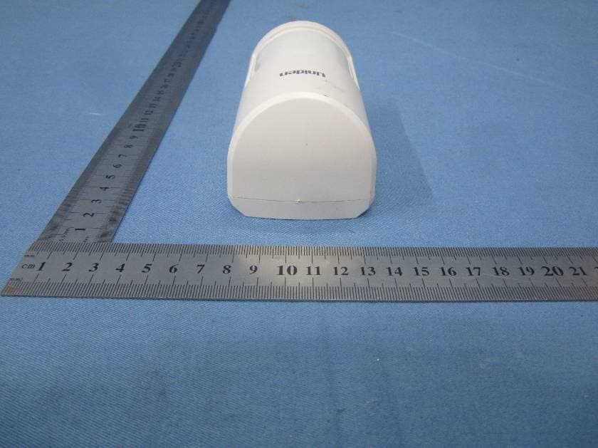
LE2PIR31
Nov 21, 2015Wireless portable / wall-mount area motion alert sensor
Equipment Class
DXX - Part 15 Low Power Communication Device Transmitter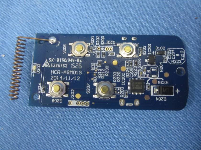
LE2RC41
Nov 21, 2015Wireless multi-functional panic remote controller
Equipment Class
DXX - Part 15 Low Power Communication Device Transmitter
LE2APPCAM26PTA
Jun 13, 2015720p PT WIFI Camera
Equipment Class
DTS - Digital Transmission System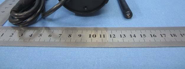
LE2APPCAM25HDA
May 25, 2015720p WIFI Camera
Equipment Class
DTS - Digital Transmission System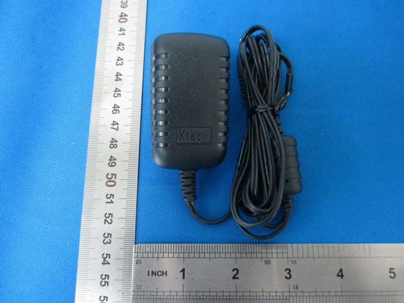
LE2APPCAM24HD
May 24, 2015720p WIFI Camera
Equipment Class
DTS - Digital Transmission System