LE2MSTR51Smart wireless central home control / management center
JSW Pacific Corporation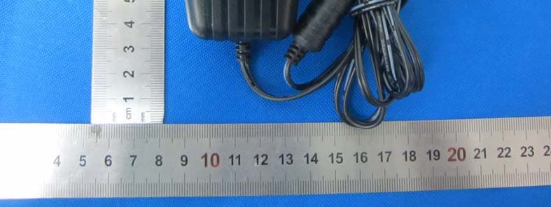
Click to zoom
Application Details
- Equipment Class
- DXX - Part 15 Low Power Communication Device Transmitter
- Date of Grant
- Mar 21, 2015
- Application Purpose
- Original Equipment
- Date of Application
- Mar 21, 2015
- Equipment Note
- Smart wireless central home control / management center
- Frequency Range
- 916.80000000 - 916.80000000
- Company
- JSW Pacific Corporation
- Country
- Taiwan
Documents & Files
Document Text
Text extracted from the exhibit documents filed with the FCC. Open a document above to read the original.
Users Manual
QUICK START GUIDE KIT CONTENT SYSTEM INTRODUCTION GETTING STARTED 1. Connect the gateway box to the Internet (1) Connect gateway box to your router via the Ethernet cable. Then plug in the supplied power cable. (2) The power LED indicator becomes steady RED and you will hear the gateway box beep twice. This means the gateway box is ready for APP setup. (3) Launch 'OMGUARD SHC' APP. The APP will automatically search the available gateway box and brings up the system DID/password. If it is not shown, Please check the system DID on the bottom of the gateway box. Enter the system DID and default password 123456 manually. Note: The gateway box should be powered on and connected to the Internet at all times. You can continue to setup the camera and sensor(s) now. 2. Set up the IP Camera (1) Connect the IP Camera to your router via the Ethernet cable . (2) Plug in the power adapter and wait until both RED and GREED LED begin flashing. Note: DO NOT begin the APP setup process until both LEDs become steady on. Adaptor DC12V/1A Adaptor DC12V/1A Adaptor DC12V/1A Adaptor DC12V/1A Ethernet cable 2M Battery AA 1.5V Battery AA 1.5V x 3 NA Sticky padScrew Battery CR2032 Sticky pad Adaptor DC 5V/1 ABattery AA 1.5V orBattery AA 1.5V x 4 Bracket x 1 Adaptor DC 5V/1.5A x 1 x 1 x 3x 4x 4 x 1x 3x 4 x 1x 4x 1 Battery CR2032 x 1 Screw x 2 Screw Gayway IP Camera Motion PIR On / Off Switch Door / Window Sensor Indoor Siren Panic Remote Steady RED (3) Launch the 'OMGUARD SHC' APP. Click the 'ADD' iconand choose 'Camera' to add the device to system. Follow the APP wizard setup process to add the camera. Note: The APP will search the available IP Camera in LAN area. If the camera you're setting doesn't appear in the searching list, please enter the camera ID (DID) and password manually. Installing the IP Camera: (1) Secure the camera stand on the stable surface. (2) Mount the camera into camera stand. Adjust the viewing angle and fix the camera tightly. 3. Pair the Motion Sensor Launch the 'OMGUARD SHC' APP. Click the 'ADD' icon and choose 'Motion Sensor' and to initiate the pairing process, following with pressing the pairing button located inside the battery compartment to complete the process. Installing the Motion Sensor: (1) Place the motion sensor upward, facing the location to be monitored. The detection distance is up to 16 meteres. For maximum coverage, it is recommanded to place the motion sensor highup with its back against the corner of walls to ensure best detection coverage. (2) Use the double-sided tape to fix the motion sensor. OMGUARDSHC OMGUARDSHC OMGUARDSHC Ethernet cable 2M x 1 Gateway Smart wireless central home control / management center. Door / Window Sensor Wireless door / window access alert sensor. Indoor Siren Wireless portable / wall- mount alert siren. Panic Remote Wireless multi-functional panic remote controller. IP Camera Wireless day / night portable motion alert indoor camera. Motion PIR Wireless portable / wall- mount area motion alert sensor. On / Off Switch Wireless appliance energy management power switch / signal repeater (single device) Remove the insulating plastic Remove the insulating plastic 16 meters ? 4. Pairing the Power Switch Launch the 'OMGUARD SHC' APP. Click the 'ADD' icon and choose ‘Power Switch' and to initiate the pairing process, following with press/hold the front panel button until LED flashing blue. To initiate the repeater function, press / hold the front panel button turned orange, following with pressing the pairing button on the device . 5. Pairing the Door / Window Sensor Launch the 'OMGUARD SHC' APP. Click the 'ADD' icon and choose 'Door Sensor' andto initiate the pairing process, following with removing and reinstalling the battery compartment cover to complete the process. Installing the Door/Window Sensor Using the double-sided tape: (1) Apply the double-sided tape to the backs of the Door/Window sensor. (2) Select a location on the door/window. The large piece of the sensor should be fixed on the immovable frame of the door/window. Align the small piece to the large one. Fix the small piece on the movable part of the door/window frame. (3) When it is finished, open the door or window to test if the sensor has been correctly installed. You'll receive an alert from the mobile device if the APP and sensor have been corrected installed. FCC Compliance Statement: This device complies with Part 15 of the FCC rules. Operation is subjected to the following two conditions: (1)this device may not cause harmful interference, and (2) this device must accept any interferencereceived, including interference that may cause undesired operation. Products with CE Marking comply with EMC Directive (2004/108/EC); Low Voltage Directive (73/23/EEC); R&TTE (1999/5/EC); ROHS Directive (2011/65/EU) issued by the Commission of the European Community. Compliance with these directives implies conformity to the following European Norms: EMC: EN 301 489 LVD: EN 60950 Radio: EN 300 328 If the camera system no longer functions or can no longer be repaired, it must be disposed of according to the valid statutory regulations. Disposal of spent batteries/accumulators: You are required by law (Battery Ordinance) to return all spent batteries and accumulators. Disposing of spent batteries/accumulators with common household waste is prohibited! Batteries/accumulators that contain hazardous substances are marked with the symbols on the side. These symbols indicate that it is prohibited to dispose of these batteries/accumulators in the household waste. The abbreviations for the respective heavy metals are: Cd=cadmium, Hg=mercury, Pb=lead. You can return spent batteries and accumulators that can no longer be charged to the designated collection points in your community, outlets or wherever batteries or accumulators are sold. Following these instructions will allow you to fulfill the legal requirements and contribute to the protection of our environment! Using the mounting screws: (1) Fi…
Text truncated - open the document above for the full version.
Cover Letter(s)
(Please print this form on your headed company notepaper) DATE :2015-3-10 Equipment Autorisation Division Federal Communications Commission 7435 Oakland Mills Road Columbia, MD 21046 FCC ID: LE2MSTR51 Product Name: Smart wireless central home control / management center Request for Confidentiality Pursuant to Sections 0.457 and 0.459 of the commissions rules, we hereby request that the following documents be held confidential: Exhibit Type Description ☒ Schematics All circuitry of devices and component values ☒ Block Diagrams Details of device showing the frequency of all oscillators ☒ Operational Description Description of the circuit functions These materials contain trade secrets and proprietary information and are not customarily released to the public. The public disclosure of this information might be harmful to the company and provide unjustified benefits to our competitors. Yours sincerely, Signatory Name Min Chen Position Engineer Company Name JSW Pacific Corporation Address 3F-3, No.700, Chung Cheng Rd, Chung-Ho Dist., New Taipei City 235, Taiwan Tel / Fax 886-2-2242-9020 E-Mail [email protected]
External Photos
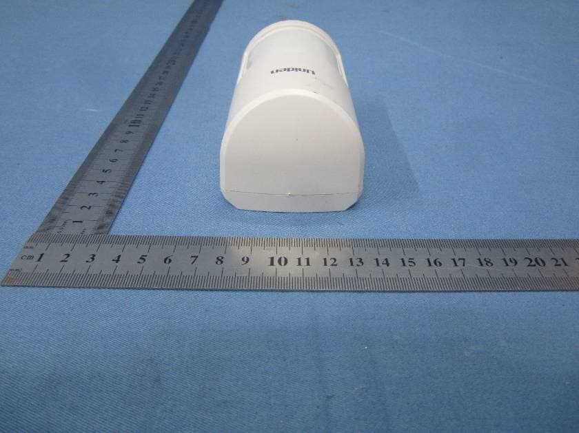
Dongguan Dongdian Testing Service Co., Ltd Report No: DDT-R15Q0309-1E1 Page 31 of 40 8. Photos of the EUT Dongguan Dongdian Testing Service Co., Ltd Report No: DDT-R15Q0309-1E1 Page 32 of 40 Dongguan Dongdian Testing Service Co., Ltd Report No: DDT-R15Q0309-1E1 Page 33 of 40 Dongguan Dongdian Testing Service Co., Ltd Report No: DDT-R15Q0309-1E1 Page 34 of 40 Dongguan Dongdian Testing Service Co., Ltd Report No: DDT-R15Q0309-1E1 Page 35 of 40
Internal Photos
Dongguan Dongdian Testing Service Co., Ltd Report No: DDT-R15Q0309-1E1 Page 36 of 40 Dongguan Dongdian Testing Service Co., Ltd Report No: DDT-R15Q0309-1E1 Page 37 of 40 Dongguan Dongdian Testing Service Co., Ltd Report No: DDT-R15Q0309-1E1 Page 38 of 40 Dongguan Dongdian Testing Service Co., Ltd Report No: DDT-R15Q0309-1E1 Page 39 of 40 Dongguan Dongdian Testing Service Co., Ltd Report No: DDT-R15Q0309-1E1 Page 40 of 40 END OF REPORT
RF Exposure Info
RF Exposure evaluation According to KDB 447498 D01 General RF Exposure Guidance v05 The 1-g and 10-g SAR test exclusion thresholds for 100 MHz to 6 GHz at test separation distances ≤ 50 mm are determined by: [(max. power of channel, including tune-up tolerance, mW)/(min. test separation distance, mm)] ·[√f(GHz)] ≤ 3.0 for 1-g SAR and ≤ 7.5 for 10-g extremity SAR, where f(GHz) is the RF channel transmit frequency in GHz Power and distance are rounded to the nearest mW and mm before calculation The result is rounded to one decimal place for comparison eirp = pt x gt = (EXd) 2 /30 where: pt = transmitter output power in watts, gt = numeric gain of the transmitting antenna (unitless), E = electric field strength in V/m, --- 10 ((dBuV/m)/20) /10 6 d = measurement distance in meters (m)---3m So pt = (EXd) 2 /30 x gt Field strength =76.96dBuV/m @3m Ant gain 2dBi; so Ant numeric gain=1.58 So pt={[10 (76.96/20) /10 6 x3] 2 /30x1.58}x1000 mW =0.01 mW So (0.01mW/5mm)x √0.9168 GHz = 0.002<3 Then SAR evaluation is not required
Test Report
Dongguan Dongdian Testing Service Co., Ltd Report No:DDT-R15Q0309-1E1 Page 1 of 40 FCC CERTIFICATION TEST REPORT FOR Issued By: Dongguan Dongdian Testing Service Co., Ltd. Add: No. 17, Zongbu Road 2, Songshan Lake Sci&Tech, Industry Park, Dongguan City, Guangdong Province, China, 523808 Tel: +86-0769-22891499 http://www.dgddt.com Applicant : JSW Pacific Corporation Address : 3F-3, No.700, Chung Cheng Rd, Chung-Ho Dist., New Taipei City 235, Taiwan Equipment under Test : Smart wireless central home control / management center Model No : MSTR51 FCC ID : LE2MSTR51 Manufacturer : JSW Pacific Corporation Address : 3F-3, No.700, Chung Cheng Rd, Chung-Ho Dist., New Taipei City 235, Taiwan Report No: DDT-R15Q0309-1E1 Issued Date: Mar. 18, 2015 Dongguan Dongdian Testing Service Co., Ltd Report No:DDT-R15Q0309-1E1 Page 2 of 40 TABLE OF CONTENTS Test report declares......................................................................................................................3 1. Summary of test results ............................................................................................................... 4 2. General test information .............................................................................................................. 5 2.1. Description of EUT ..................................................................................................................... 5 2.2. Accessories of EUT..................................................................................................................... 5 2.3. Assistant equipment used for test ................................................................................................ 5 2.4. Block diagram of EUT configuration for test ............................................................................. 5 2.5. Test environment conditions ....................................................................................................... 6 2.6. Test laboratory............................................................................................................................. 6 2.7. Measurement uncertainty ............................................................................................................ 6 3. 20dB Bandwidth.......................................................................................................................... 7 3.1. Test equipment ............................................................................................................................ 7 3.2. Block diagram of test setup ......................................................................................................... 7 3.3. Limits .......................................................................................................................................... 7 3.4. Test Procedure............................................................................................................................. 7 3.5. Test Result................................................................................................................................... 8 3.6. Original test data ......................................................................................................................... 8 4. Radiated emission ....................................................................................................................... 9 4.1. Test equipment ............................................................................................................................ 9 4.2. Block diagram of test setup ......................................................................................................... 9 4.3. Limit .......................................................................................................................................... 11 4.4. Test Procedure........................................................................................................................... 12 4.5. Test result .................................................................................................................................. 13 5. Power Line Conducted Emission .............................................................................................. 22 5.1. Test equipment .......................................................................................................................... 22 5.2. Block diagram of test setup ....................................................................................................... 22 5.3. Power Line Conducted Emission Limits(Class B) .................................................................... 22 5.4. Test Procedure........................................................................................................................... 22 5.5. Test Result................................................................................................................................. 23 6. Antenna Requirements .............................................................................................................. 28 6.1. Limit .......................................................................................................................................... 28 6.2. Result......................................................................................................................................... 28 7. Test setup photograph ............................................................................................................... 29 8. Photos of the EUT ..................................................................................................................... 31 Dongguan Dongdian Testing Service Co., Ltd Report No:DDT-R15Q0309-1E1 Page 3 of 40 TEST REPORT DECLARE Test Standard Used: FCC Rules and Regulations Part 15 Subpart C: 2012 Test procedure used: ANSI C63.10:2009, ANSI C63.4:2009. We Declare: The equipment described above is tested …
Text truncated - open the document above for the full version.
Test Setup Photos
Dongguan Dongdian Testing Service Co., Ltd Report No: DDT-R15Q0309-1E1 Page 29 of 34 7. Test setup photograph Dongguan Dongdian Testing Service Co., Ltd Report No: DDT-R15Q0309-1E1 Page 30 of 34
Contact Information
Applicant
Min Hui Chen(Vice President)
Test Firm
Dongguan Dongdian Testing Service Co.,LtdJamy Yu
[email protected]086-0769-22891499
Technical Specifications
| # | Rule Parts | Frequency Range | Power Output |
|---|---|---|---|
| 1 | 15C | 916.8 MHz - 916.8 MHz | - |
Other Applications from JSW Pacific Corporation
LE2PIR31
Nov 21, 2015Wireless portable / wall-mount area motion alert sensor
Equipment Class
DXX - Part 15 Low Power Communication Device Transmitter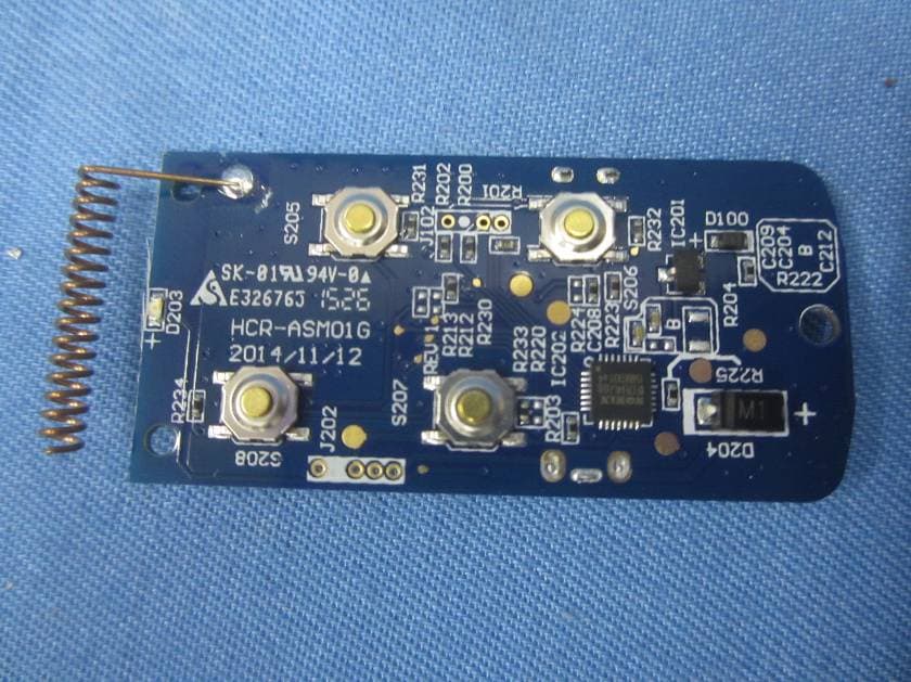
LE2RC41
Nov 21, 2015Wireless multi-functional panic remote controller
Equipment Class
DXX - Part 15 Low Power Communication Device Transmitter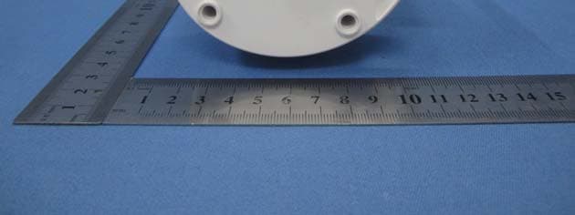
LE2APPCAM26PTA
Jun 13, 2015720p PT WIFI Camera
Equipment Class
DTS - Digital Transmission System
LE2APPCAM25HDA
May 25, 2015720p WIFI Camera
Equipment Class
DTS - Digital Transmission System
LE2APPCAM24HD
May 24, 2015720p WIFI Camera
Equipment Class
DTS - Digital Transmission System