LE2RC-820Radio Clock With Hidden Camera
JSW Pacific Corporation
Click to zoom
Application Details
- Equipment Class
- DXX - Part 15 Low Power Communication Device Transmitter
- Date of Grant
- Apr 27, 2003
- Application Purpose
- Original Equipment
- Date of Application
- Apr 27, 2003
- Equipment Note
- Radio Clock With Hidden Camera
- Frequency Range
- 2412.00000000 - 2472.00000000
- Company
- JSW Pacific Corporation
- Country
- Taiwan
Documents & Files
Document Text
Text extracted from the exhibit documents filed with the FCC. Open a document above to read the original.
Users Manual
User's Manual Model No.: RC-820 2.4 GHz Wireless Color Hidden Camera with AM/FM Radio Alarm Clock System - AM/FM 2-Band Radio Alarm Clock with Build-In Camera and Microphone - Receiver with Patch Antenna PLEASE READ CAREFULLY AND SAVE This manual contains important information about this product's operation. If you are installing this product for use by others you must leave this manual -or a copy- with the end user. Navigator R Model No.: RC-820 2.4 GHz Wireless Color Hidden Camera with AM/FM Radio Alarm Clock System Contents Important Safety Precautions ..................................1 Specifications ............................................................2 Parts Included with This System .............................3 Parts of the System ..................................................3 - Parts of the Radio/Camera ....................................3 - Parts of the Receiver .............................................3 The AM/FM Radio Alarm Clock ................................3 - Power Supply .........................................................3 - Clock/Radio Operation ...........................................4 - Sleep Timer ............................................................4 - Sleep Time and Alarm Usage ................................4 Installing the Wireless Color Hidden Camera System ............................................5 Rotating the Antenna for Best Performance ..........6 The Auto-Sequence Function ..................................6 Connecting the Receiver to a TV or Monitor ..........6 Troubleshooting Guide .............................................7 Warranty .....................................................................7 You should... 1. Check that the power cord(s) is properly connected. 2. Check that the monitor is turned ON. 3. Wrong AC/DC adapter used. Check if your are using the right AC/DC adapter. 1. Check the channel switch settings on the camera/radio and receiver. Make sure the channels match on both units. 2. Signal interference from a microwave oven. Check if a micro-wave oven is in use or located in the path between the camera/radio and receiver. If so, turn it off or move it out of the path. 3. Signal interference from other signal producing devices. (a) Change the channel setting on both camera/radio and receiver. (b) Identify and eliminate the source of the interference. (c) Relocate the camera/radio and/or receiver closer to each other. 4. Camera/radio and receiver are too far apart. Relocate the camera/radio closer to the receiver. 5. Antenna is positioned improperly. Adjust the antenna on the receiver. Troubleshooting Guide If the Camera/Radio and/or Monitor... No Power No sound or picture. Distorted sound or picture 7 1 Year Limited Warranty: JSW Pacific Corp., the maker of Navigator“ brand products, warrants that for a period of 1 year from the date of purchase, this product will be free from defects in material and workmanship. JSW, at its option, will repair or replace this product or any component of the product found to be defective during the warranty period. Replacement will be made with a new or remanufactured product or component. If the product is no longer available, replacement may be made with a similar product of equal or greater value. This is your exclusive warranty. This warranty is valid for the original purchaser from the date of initial purchase with JSW and is not transferable. This warranty does not cover normal wear of parts or damage resulting from any of the following: negligent use or misuse of the product, use on improper voltage or current, use contrary to the operating instructions, disassembly, repair or alteration by anyone other than JSW or an authorized service center. Further, the warranty does not cover acts of God, such as fire, flood, hurricanes and tornadoes or any batteries that are included with this unit. JSW shall not be liable for any incidental or consequential damages caused by the breach of any express or implied warranty. 16 Rotating the Antenna for Best Performance This system broadcasts its high-quality audio and video using directional antenna. The antenna can rotate in either clockwise or counterclockwise directions to obtain the best signal and picture clarity. In most situations, additional adjusting of the antenna may be necessary to get optimal performance. If the camera/radio and receiver are less than 10 feet apart, leave the antenna in the closed (down) position. See the instructions shown on the right to rotate the antenna. The Auto Sequence Feature The Wireless Color Hidden Camera System can be set up to monitor a series of rooms in a home or office. The receiver can connect up to four cameras on four different channels for both Audio/Video reception, and display them in auto sequence. The system has dip-switches for 4 channels to allow various monitoring options. When the channel dip-switches are set in the "ON" position, that channel is active on the receiver and can be seen on the TV or monitor. Channel dip-switches in the "OFF" position are inactive and will not be shown on the TV or monitor. The auto-sequence feature is activated when more than one channel is switched ON. The channels switched ON will display on the monitor at five second intervals. For example, if you have two cameras, one set to Channel 1 and the other set to channel 3, the dip-switch on the receiver must be set for both channels 1 and 3. Then camera one [CH1] and camera two [CH3] will start to display on the TV or monitor in sequence at five seconds intervals. This interval time is preset by the factory and cannot be adjusted by the user. To stop the auto-sequence function: Slide the dip-switch of the channel(s) you do not want displayed to OFF on both that camera and the receiver. Channels in the OFF position will no longer be displayed. Connecting the Receiver to a TV or Monitor The receiver has an audio/video output which is for transferring the picture and sound from the …
Text truncated - open the document above for the full version.
Cover Letter(s)
From: S. S. Liou [[email protected]] Sent: Monday, April 28, 2003 3:21 AM To: Mike Kuo Subject: Re: JSW PACIFIC CORPORATION, FCC ID:LE2LE2RC-820, AN03T2802 Hello Mike, For your questions, 1. Please refer to attached test report for revised data. The average readings are provided on page 12 and 13. 2. For measuring frequency higher than 18GHz the EMCO antenna 3116 is used. Please refer to page 10 of the revised test report. 3. Please find attached schematic diagram. regards, S. S. Liou Engineer / EMC Dep. II ETC ----- Original Message ----- From: "Mike Kuo" <[email protected]> To: "ETC/Iris (E-mail)" <[email protected]>; "Will Yauo (E-mail)" <[email protected]> Sent: Friday, April 25, 2003 6:46 AM Subject: FW: JSW PACIFIC CORPORATION, FCC ID:LE2LE2RC-820, AN03T2802 > > > -----Original Message----- > From: CERTADM > Sent: Thursday, April 24, 2003 3:46 PM > To: '[email protected]' > Subject: JSW PACIFIC CORPORATION, FCC ID:LE2LE2RC-820, AN03T2802 > > > Notice_content > ------------- > Question #1: Page 13 of test report, the peak reading is higher than the > average limits. Per 15.249(d) of FCC rules, please provide average reading > to demonstrate compliance. > > Question #2: EMCO 3115 antenna is only capable of measuring upto 18GHz but > tabular data indicated the frequencies were investigated with EMCO 3115 > antenna beyond 18GHz. Please explain. > > Question #3: Please provide schematic diagram. > > Best Regards > > > Mike Kuo > The items indicated above must be submitted before processing can continue > on the above referenced application. Failure to provide the requested > information within 60 days of the original e-mail date may result in > application dismissal and forfeiture of the filing fee. Also, please note > that partial responses increase processing time and should not be submitted. > Any questions about the content of this correspondence should be directed to > the e-mail address listed below the name of the sender.
External Photos
ETC Report No. : ET92R-03-093 Sheet 1 of 15 Sheets FCC ID.: LE2RC-820 Rev. No 1.0 CONSTRUCTION PHOTOS OF EUT 1. Top View of Transmitter 2. Bottom View of Transmitter ETC Report No. : ET92R-03-093 Sheet 2 of 15 Sheets FCC ID.: LE2RC-820 Rev. No 1.0 CONSTRUCTION PHOTOS OF EUT 3. Side View of Transmitter 4. Side View of Transmitter ETC Report No. : ET92R-03-093 Sheet 3 of 15 Sheets FCC ID.: LE2RC-820 Rev. No 1.0 CONSTRUCTION PHOTOS OF EUT 5. Front View of Transmitter 6.Rear View of Transmitter ETC Report No. : ET92R-03-093 Sheet 13 of 15 Sheets FCC ID.: LE2RC-820 Rev. No 1.0 CONSTRUCTED PHOTOS of EUT 24. Front View of Adaptor 25. Rear View of Adaptor
Internal Photos
ETC Report No. : ET92R-03-093 Sheet 4 of 15 Sheets FCC ID.: LE2RC-820 Rev. No 1.0 CONSTRUCTION PHOTOS OF EUT 7. Internal View of Transmitter ETC Report No. : ET92R-03-093 Sheet 5 of 15 Sheets FCC ID.: LE2RC-820 Rev. No 1.0 CONSTRUCTION PHOTOS OF EUT 8. Component View of Main PCB 1 (Transmitter) 9. Solder View of Main PCB 1 (Transmitter) ETC Report No. : ET92R-03-093 Sheet 6 of 15 Sheets FCC ID.: LE2RC-820 Rev. No 1.0 CONSTRUCTION PHOTOS OF EUT 10. Component View of Main PCB 2 (Transmitter) 11. Solder View of Main PCB 2 (Transmitter) ETC Report No. : ET92R-03-093 Sheet 7 of 15 Sheets FCC ID.: LE2RC-820 Rev. No 1.0 CONSTRUCTION PHOTOS OF EUT 12. Component View of Main PCB 3 (Transmitter) 13. Solder View of Main PCB 3 (Transmitter) ETC Report No. : ET92R-03-093 Sheet 8 of 15 Sheets FCC ID.: LE2RC-820 Rev. No 1.0 CONSTRUCTION PHOTOS OF EUT 14. Component View of Main PCB 4 (Transmitter) 15. Solder View of Main PCB 4 (Transmitter) ETC Report No. : ET92R-03-093 Sheet 9 of 15 Sheets FCC ID.: LE2RC-820 Rev. No 1.0 CONSTRUCTION PHOTOS OF EUT 16. Component View of Main PCB 5 (Transmitter) 17. Solder View of Main PCB 5 (Transmitter) ETC Report No. : ET92R-03-093 Sheet 10 of 15 Sheets FCC ID.: LE2RC-820 Rev. No 1.0 CONSTRUCTION PHOTOS OF EUT 18. Component View of Main PCB 6 (Transmitter) 19. Solder View of Main PCB 6 (Transmitter) ETC Report No. : ET92R-03-093 Sheet 11 of 15 Sheets FCC ID.: LE2RC-820 Rev. No 1.0 CONSTRUCTION PHOTOS OF EUT 20. Component View of Main PCB 7 (Transmitter) 21. Solder View of Main PCB 7 (Transmitter) ETC Report No. : ET92R-03-093 Sheet 12 of 15 Sheets FCC ID.: LE2RC-820 Rev. No 1.0 CONSTRUCTION PHOTOS OF EUT 22. Component View of Main PCB 8 (Transmitter) 23. Solder View of Main PCB 8 (Transmitter) ETC Report No. : ET92R-03-093 Sheet 14 of 15 Sheets FCC ID.: LE2RC-820 Rev. No 1.0 CONSTRUCTED PHOTOS of EUT 26. Internal View of Adaptor 27. Component View of Adaptor’s PCB ETC Report No. : ET92R-03-093 Sheet 15 of 15 Sheets FCC ID.: LE2RC-820 Rev. No 1.0 CONSTRUCTED PHOTOS of EUT 28. Internal View of Adaptor
Test Report
Rev. No 1.0 FCC Part 15 EMI TEST REPORT of E.U.T. : Radio Clock with Hidden Camera MODEL : RC-820 FCC ID. : LE2RC-820 for APPLICANT : JSW PACIFIC CORPORATION. ADDRESS : 7 TH FLOOR, NO. 168-1, LIEN CHENG ROAD, CHUNG HO CITY, TAIPEI HSIEN TAIWAN, R.O.C. Test Performed by ELECTRONICS TESTING CENTER, TAIWAN NO. 34, LIN 5, DING FU TSUN, LINKOU HSIANG TAIPEI HSIEN, TAIWAN, R.O.C. Tel:(02)26023052, Fax:(02)26010910 Report Number : ET92R-03-093 ETC Report No. : ET92R-03-093 FCC ID. : LE2RC-820 Rev. No 1.0 TEST REPORT CERTIFICATION Applicant : JSW PACIFIC CORPORATION 7TH FLOOR, NO. 168-1, LIEN CHENG ROAD, CHUNG HO CITY, TAIPEI HSIEN TAIWAN, R.O.C.. Manufacturer : JSW PACIFIC CORPORATION 7TH FLOOR, NO. 168-1, LIEN CHENG ROAD, CHUNG HO CITY, TAIPEI HSIEN TAIWAN, R.O.C. Description of EUT : a) Type of EUT : Radio Clock with Hidden Camera b) Trade Name : Navigator c) Model No. : RC-820 d) Power Supply : Adaptor: I/P: AC120V, 60Hz ; O/P: AC10.2V, 250mA e) Working Frequency : 2400MHz~2483.5MHz Regulation Applied : FCC Rules and Regulations Part 15 Subpart C (2002) I HEREBY CERTIFY THAT: The data shown in this report were made in accordance with the procedures given in ANSI C63.4, and the energy emitted by the device was founded to be within the limits applicable. I assume full responsibility for accuracy and completeness of these data. Note: 1. The result of the testing report relate only to the item tested. 2. The testing report shall not be reproduced expect in full, without the written approval of ETC. Issued Date : Apr. 18, 2003 Test Engineer : ( Kevin Lee ) Approve & Authorized Signer : Will Yauo, Manager EMC Dept. II of ELECTRONICS TESTING CENTER, TAIWAN ETC Report No. : ET92R-03-093 FCC ID. : LE2RC-820 Rev. No 1.0 Table of Contents Page 1 GENERAL INFORMATION.......................................................................................................1 1.1 Product Description...................................................................................................................1 1.2 Characteristics of Device..........................................................................................................1 1.3 Test Methodology......................................................................................................................1 1.4 Test Facility................................................................................................................................1 2 PROVISIONS APPLICABLE.......................................................................................................2 2.1 Definition....................................................................................................................................2 2.2 Requirement for Compliance....................................................................................................3 2.3 Restricted Bands of Operation..................................................................................................5 2.4 Labeling Requirement................................................................................................................5 2.5 User Information........................................................................................................................6 3. SYSTEM TEST CONFIGURATION...........................................................................................7 3.1 Justification................................................................................................................................7 3.2 Devices for Tested System........................................................................................................7 4 RADIATED EMISSION MEASUREMENT..............................................................................8 4.1 Applicable Standard....................................................................................................................8 4.2 Measurement Procedure...........................................................................................................8 4.3 Measuring Instrument..............................................................................................................10 4.4 Radiated Emission Data...........................................................................................................11 4.4.1 RF Portion...............................................................................................................................11 4.4.2 Other Emission........................................................................................................................14 4.5 Field Strength Calculation.......................................................................................................14 4.6 Photos of Radiation Measuring Setup....................................................................................15 5 CONDUCTED EMISSION MEASUREMENT........................................................................16 5.1 Standard Applicable..................................................................................................................16 5.2 Measurement Procedure.........................................................................................................16 5.3 Conducted Emission Data.......................................................................................................17 5.4 Result Data Calculation...........................................................................................................18 5.5 Conducted Measurement Equipment......................................................................................19 5.6 Photos of Conduction Measuring Setup................................................................................20 6 ANTENNA REQUIREMENT....................................................................................................21 6.1 Standard Applicable.........................................................................…
Text truncated - open the document above for the full version.
Contact Information
Applicant
Min Hui Chen(Vice President)
Test Firm
Electronics Testing Center, TaiwanWinpo Tsai
Technical Specifications
| # | Rule Parts | Frequency Range | Power Output |
|---|---|---|---|
| 1 | 15C | 2.41 GHz - 2.47 GHz | - |
Other Applications from JSW Pacific Corporation
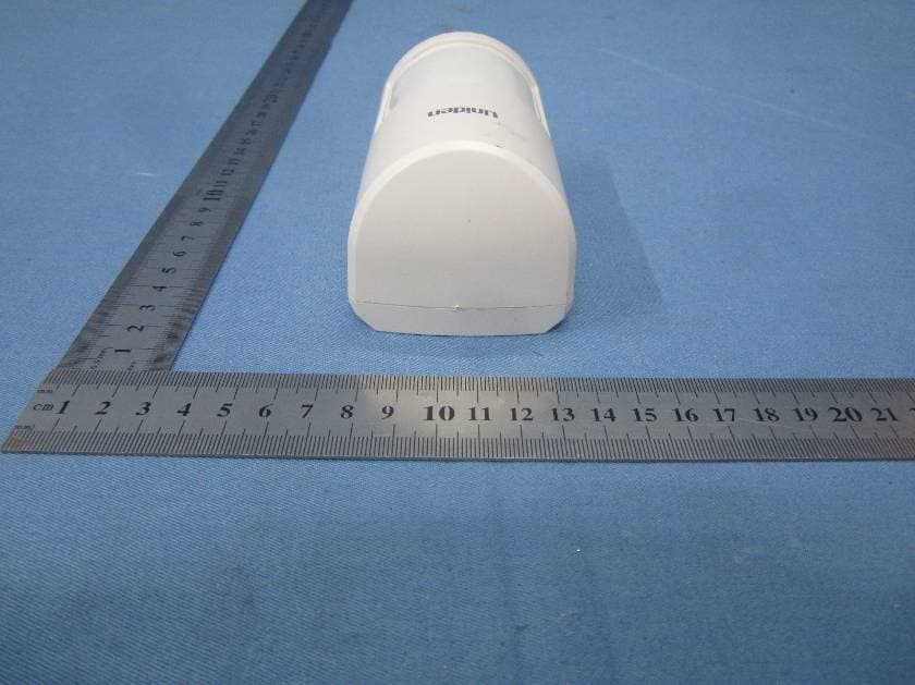
LE2PIR31
Nov 21, 2015Wireless portable / wall-mount area motion alert sensor
Equipment Class
DXX - Part 15 Low Power Communication Device Transmitter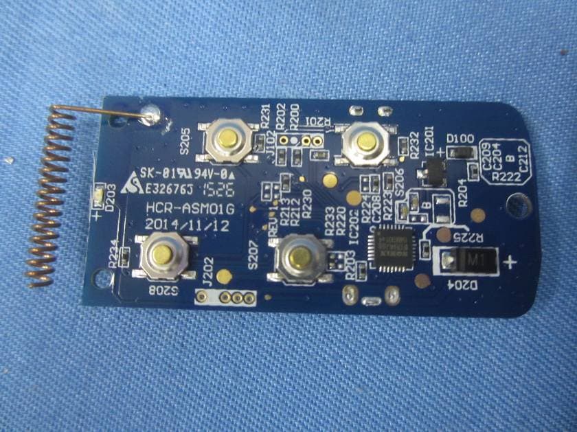
LE2RC41
Nov 21, 2015Wireless multi-functional panic remote controller
Equipment Class
DXX - Part 15 Low Power Communication Device Transmitter
LE2APPCAM26PTA
Jun 13, 2015720p PT WIFI Camera
Equipment Class
DTS - Digital Transmission System
LE2APPCAM25HDA
May 25, 2015720p WIFI Camera
Equipment Class
DTS - Digital Transmission System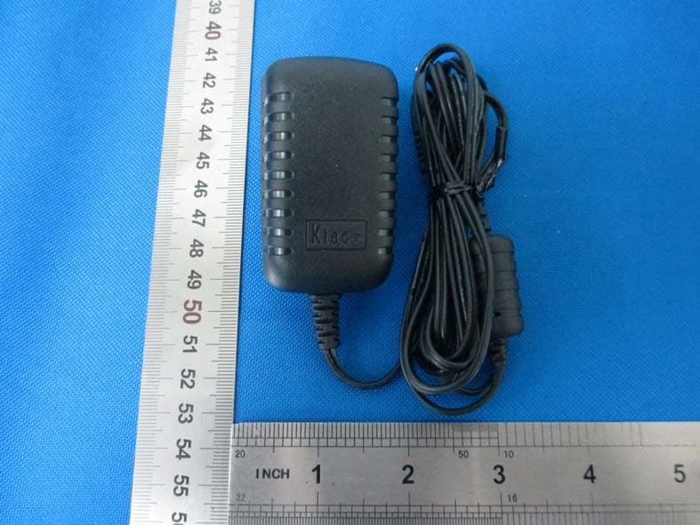
LE2APPCAM24HD
May 24, 2015720p WIFI Camera
Equipment Class
DTS - Digital Transmission System