LJL02011032Remote Control Transmitter
Lite On Automotive Corporation
Click to zoom
Application Details
- Equipment Class
- DSC - Part 15 Security/Remote Control Transmitter
- Date of Grant
- Nov 25, 2003
- Application Purpose
- Original Equipment
- Date of Application
- Nov 25, 2003
- Equipment Note
- Remote Control Transmitter
- Frequency Range
- 433.84000000 - 433.84000000
- Country
- Taiwan
Documents & Files
Document Text
Text extracted from the exhibit documents filed with the FCC. Open a document above to read the original.
Users Manual
USER GUIDE SYSTEM 3 SYSTEM 21 02005084 06/2003 even if you read nothing else - READ THESE 2 POINTS! KEEP WITH YOUR MOTORCYCLE IN PLASTIC BAG PROVIDED Set your own individual PIN OVERRIDE This will let you disarm the system if you lose the remote transmitter. See pages 6 to 8 All references to System 3 apply to System 21 unless otherwise stated ALWAYS CARRY A SPARE IN-LINE FUSE Make sure your installer advises you of the location of the in-line fuse. If the fuse fails, your motorcycle will be immobilised until it is replaced. MAIN SYSTEM COMPONENTS Two Remote Transmitters Installed Control Unit Customising Wires Installed Protective Trigger Switch Installed In-Line Fuse and Spare Fuse Installed LED Alarm Indicator Warning Labels WARNING UNAUTHORISED ALTERATIONS OR ADDITIONS MAY INVALIDATE THE WARRANTY AND CERTIFICATE OF INSTALLATION Page 1 INITIAL OPERATION - STANDARD MODE When you collect your motorcycle, the Datatool System will be armed in STANDARD MODE. In this mode the system arms automatically, 30 seconds after you switch off the ignition. Before moving or starting your motorcycle, You will need to DISARM the system. TO DISARM THE SYSTEM TO ARM THE SYSTEM The system will arm again automatically after 30 seconds if the ignition isn’t turned ON. The system will arm automatically 30 seconds after the ignition is switched OFF, or you can arm the system manually before this time. FULL ALARM REACTION Once triggered, the audible alarm will sound and the indicators will flash for 30 seconds, the alarm will then switch off and reset automatically (See Diagnostic Mode). To switch OFF the alarm manually, use the transmitter. Page 2 In normal setting, movement/nudge detection is enabled automatically when the system arms. Warning beeps will sound if the motorcycle is nudged or moved, too many beeps within a certain time will initiate a full reaction. IGNITION CIRCUIT If the circuit is hotwired, or the ignition is forced. BATTERY CIRCUIT If any part of the circuit becomes live, or the battery connection is cut. MOVEMENT If the motorcycle is moved or nudged (with movement/ nudge detection on). TAMPER If there is any attempt to gain access to the alarm control unit. Four elements of the motorcycle are monitored and will initiate a full reaction if any of the following occurs. Movement/Nudge detection should be disarmed when you are filling with petrol at a garage, or moving the motorcycle with the ignition off. NEVER LEAVE THE MOTORCYCLE UNATTENDED WHEN MOVEMENT/NUDGE DETECTION IS DISABLED MOVEMENT/NUDGE DETECTION OPERATION OVERVIEW Page 3 OPERATION - SERVICE/VALET MODE IMPORTANT Protective Trigger Switch A Protective Trigger Switch is fitted to protect the System Control Unit from access eg: under the seat, side panel or petrol tank. In normal operation, if this is tampered with a full alarm reaction will be initiated. In Service Mode, the Protective Trigger Switch is disarmed allowing access to the area protected by it. YOUR MOTORCYCLE IS COMPLETELY UNPROTECTED IN SERVICE MODE Engage Service Mode when you wish to service or clean your motorcycle, or remove the motorcycle battery. IMPORTANT If after entering service/valet mode you get more than one audible beep every 15 seconds, the system has been triggered in your absence and you have automatically entered diagnostic mode (see diagnostics table on page 9). Page 4 HAZARD WARNING LIGHTS A hazard warning lights function is included. To switch off the hazard warning lights, but leave the system armed, press both buttons together for 3 seconds. To switch off the hazard warning lights, and disarm the system, press the round button. NOTE: When entering Hazard Warning Lights Mode, the hazard warning lights flash 5 times then stop. The motorcycle battery is too low to maintain this mode. SLEEP MODE If the level of charge in your motorcycle battery drops, the system will go into Sleep Mode conserving remaining power. NOTE:If the system does not come out of sleep mode in the normal way, hold the transmitter button down, at the same time turn on the ignition. Page 5 RIDER OPTION - Siren Tone Selector You can choose one of eight individual siren tones. The siren tone will be subdued during the selection process. RIDER OPTION - Arming the system without Movement/Nudge Function RIDER OPTION - Arming/Disarming the system in Silent Mode The System can be programmed to arm with the movement/nudge function disarmed (Ferry Mode). This is achieved by securely grounding the Yellow wire. NOTE:If you arm the system manually with the transmitter (within 30 seconds of turning the ignition off) the system will arm with movement/nudge function armed. Movement/nudge detection can be switched ON/OFF at any time with the transmitter when the system is armed. The System can be programmed to arm/disarm in silent mode. This is achieved by securely grounding the white wire. Page 6 PIN OVERRIDE - INITIAL PIN ENTRY If your transmitter is lost or damaged, or the transmitter battery is flat, the System can be overriden by a four digit PIN (Personal Identity Number) used in conjunction with the ignition switch. The System is supplied without a PIN. We recommend that you set your own individual four digit PIN as soon as possible. The first time a new PIN is entered, you must have access to the in-line fuse. Page 7 PIN OVERRIDE - CHANGE PIN Page 8 DISARMING USING PIN OVERRIDE If your transmitter is lost or damaged, or the transmitter battery is flat, the System can be overriden by your four digit PIN used in conjunction with the ignition switch. The PIN facility can only be used after a full alarm reaction has been initiated. Until your transmitter is replaced or repaired, this procedure must be repeated to disarm the system every time it arms. Entering an incorrect PIN will initiate a full alarm reaction. Carry your spare in-line fuse and transmitter when touring. Page 9 SYSTEM REACTION DIAGNOSTICS Reaction Indication If the system has been triggered in your absence, a long audible to…
Text truncated - open the document above for the full version.
Cover Letter(s)
Request for Confidentiality 29 July 2003 PHOENIX TEST-LAB GmbH Königswinkel 10 D32825 Blomberg Germany RE: Certification Application FCC ID: LJL02011032 Please be advised that the following information is to be held confidential on behalf of Lite On Automotive Corporation: • Schematics • Block Diagram • Technical Description The application contains technical information which Lite On Automotive Corporation deems to be trade secrets and proprietary. If made public, the information might be used to the disadvantage of the applicant in the market place. Thank you for your attention to this matter. Signatory
Cover Letter(s)
Lite-On Automotive Electronics Tweelingenlaan 57 7324 BK Apeldoorn NETHERLAND Phone: +31 (55) 52619-50 Fax: +31 (55) 52619-77 PHOENIX TEST-LAB GmbH Product Certification Königswinkel 10 D 32825 Blomberg To Whom It May Concern: Please be advised that Lite-On Automotive Electronics authorizes Senton GmbH to act on our behalf, until otherwise notified, for applications submitted to PHOENIX TEST-LAB GmbH (PTL). We certify that we are not subject to denial of federal benefits, that includes FCC benefits, pursuant to Section 5301 of the Anti-Drug Abuse ACT of 1988, U.S.C.862. Further, no party, as defined in 47 CFR 1.2002 (b), to the application is subject to denial of federal benefits, that includes FCC benefits. Thank you for your attention to this matter. W. Ramsdale Product Development Manager
External Photos
EMV-Prüfzentrum EMI/EMC-Testcenter FCC ID: LJL02011032 Photo No. 1 Front of Unit EMV-Prüfzentrum EMI/EMC-Testcenter Photo No. 2 Rea r of Unit
ID Label/Location Info
FCC ID: LJL02011032
Internal Photos
EMV-Prüfzentrum EMI/EMC-Testcenter Photo No. 3 Unit disassembled EMV-Prüfzentrum EMI/EMC-Testcenter Photo No. 4 Top view of printed board EMV-Prüfzentrum EMI/EMC-Testcenter Photo No. 5 Bottom view of printed board
Test Report
EMV-Prüfzentrum EMI/EMC-Testcenter FCC-ID: Test Report No.: 52209-30278 Page 1 of 20 Pages Straubing, 08 July 2003 T E S T - R E P O R T No. 52209-30278 for Datatool System 3 Remote Control Transmitter Applicant: Liteon Automotive Electronics BV Test Specification: FCC Code of Federal Regulations, Part 15 Subpart C, Section 15.231 Note: The test data of this report relate only to the individual item which has been tested. This report shall not be reproduced except in full extent without the written approval of the testing laboratory. EMV-Prüfzentrum EMI/EMC-Testcenter FCC-ID: Test Report No.: 52209-30278 Page 2 of 20 Pages Table of Contents 1. Administrative Data.....................................................................................3 2. Identification of Test Laboratory .................................................................4 3. Operation Mode of EUT..............................................................................5 4. Configuration ..............................................................................................6 5. Measuring Methods ....................................................................................7 5.1. Field Strength of Emissions, Prescans in a fully-anechoic room (30 MHz – 1 GHz) .......................................................................8 5.2. Fieldstrength of Emissions, Measurement at Open Area Test Site (30 MHz – 1 GHz) .................................................................9 5.3. Fieldstrength of Emissions above 1 GHz ...........................................10 6. Photographs Taken During Testing ..........................................................11 7. List of Measurements ...............................................................................14 8. Referenced Regulations ...........................................................................19 Charts taken during testing ...............................................................................20 EMV-Prüfzentrum EMI/EMC-Testcenter FCC-ID: Test Report No.: 52209-30278 Page 3 of 20 Pages 1. Administrative Data Test item (EUT) Type designation Datatool System 3 Serial number(s): 001 Type of equipment: Remote Control Transmitter Parts/accessories: --- FCC-ID: Technical data Frequency range M/A Operational frequency 433.920 MHz Type of modulation 10K0A1D Pulse frequency N/A Pulse width N/A Antenna Integrated Power supply 2 x 3 V Lithium Cell Applicant: (full address) LiteOn Automotive Electronics Tweelinglaan 57 NL-7324 BK Appeldoorn Contract identification: --- Contact person: Mr. Stefan Rainer / TÜV Automotive GmbH Manufacturer: Applicant Application details Receipt of EUT: 14 May 2003 Date of test: June 2003 Note: Responsible for testing: J. Roidt Responsible for test report: J. Roidt EMV-Prüfzentrum EMI/EMC-Testcenter FCC-ID: Test Report No.: 52209-30278 Page 4 of 20 Pages 2. Identification of Test Laboratory DETAILS OF THE TEST LABORATORY COMPANY NAME: Senton GmbH EMI/EMC Test Center ADDRESS: Aeussere Fruehlingsstrasse 45 D-94315 Straubing Germany LABORATORY ACCREDITATION: DAR-Registration No. TTI-P-G 062/94-40 FCC TEST SITE LISTING INDUSTRY CANADA TEST SITE REGISTRATION IC 3050 NAME FOR CONTACT PURPOSES: Mr. Johann Roidt TELEPHONE: (+49) (0)9421 5522-0 FAX: (+49) (0)9421 5522-99 PERSONNEL INVOLVED IN THIS TEST REPORT TECHNICAL DIRECTOR: Mr. Johann Roidt RESPONSIBLE FOR TESTING: Mr. Martin Steindl RESPONSIBLE FOR TEST REPORT: Mr. Martin Steindl SUMMARY OF TEST RESULTS The tested sample complies with the requirements set forth in the FCC Code of Federal Regulations Part 15, Subpart C, Section 15.231 EMV-Prüfzentrum EMI/EMC-Testcenter FCC-ID: Test Report No.: 52209-30278 Page 5 of 20 Pages 3. Operation Mode of EUT While one button is pressed, the transmitter continuously sends the corresponding datagram. When the button is released, the transmitter stops working instantly. EMV-Prüfzentrum EMI/EMC-Testcenter FCC-ID: Test Report No.: 52209-30278 Page 6 of 20 Pages 4. Configuration Configuration of the EUT Not applicable Cables connected to the EUT Not applicable Peripheral devices connected to the EUT Not applicable EMV-Prüfzentrum EMI/EMC-Testcenter FCC-ID: Test Report No.: 52209-30278 Page 7 of 20 Pages 5. Measuring Methods EMV-Prüfzentrum EMI/EMC-Testcenter FCC-ID: Test Report No.: 52209-30278 Page 8 of 20 Pages 5.1. Field Strength of Emissions, Prescans in a fully-anechoic room (30 MHz – 1 GHz) Rules and Specifications: Sections 15.109 & 15.231 Guide: ANSI C63.4 1997 Measurement Procedure: Radiated emissions are measured over the frequency range from 30 MHz to 1 GHz. Measurements were made in both the horizontal and vertical planes of polarization in a fully anechoic room using a spectrum analyzer with the detector function set to peak and resolution bandwidth set to 100 kHz. All tests were performed at a test-distance of 3 meters. Hand-held or body-worn devices are rotated through three orthogonal axes to determine which attitude and configuration produces the highest emission relative to the limit and therefore shall be used for final testing. EUT Fully anechoic chamber 3 m test distance Spectrum Analyzer Test instruments used: No. Type Model Serial Number Manufacturer 01 Spectrum Analyzer FSP 30 100063 Rohde & Schwarz 113 Preamplifier CPA9231A 3393 Schaffner 141 Biconical antenna HK 116 829708/006 Rohde & Schwarz 143 Log. periodic antenna 3147 9112-1054 EMCO 003 Fully anechoic room No. 2 1452 Albatross Projects EMV-Prüfzentrum EMI/EMC-Testcenter FCC-ID: Test Report No.: 52209-30278 Page 9 of 20 Pages 5.2. Fieldstrength of Emissions, Measurement at Open Area Test Site (30 MHz – 1 GHz) Rules and Specifications: Sections 15.109 & 15.231 Guide: ANSI C63.4 1997 Measurement Procedure: Measurement Procedure: For final testing an open-area test-side was used. Radiated emissions are measured over the frequency range from 30 MHz to 1 GHz. Measurements were made in both the horizontal and vertical planes of polarisation at …
Text truncated - open the document above for the full version.
Test Setup Photos
EMV-Prüfzentrum EMI/EMC-Testcenter FCC-ID: Test Report No.: 52209-30278 Page 12 of 20 Pages Test setup for radiated emission measurement (fully anechoic room) EMV-Prüfzentrum EMI/EMC-Testcenter FCC-ID: Test Report No.: 52209-30278 Page 13 of 20 Pages Test setup for radiated emission measurement (open-area test-side)
Contact Information
Applicant
Steven Yang(Senior Engineer)
Technical Contact
Senton GmbHJohann Roidt
[email protected]+49 9421 55 22 13
Aeussere Fruehlingstrasse 45 · Straubing · Germany
Non-Technical Contact
Senton GmbHJohann Roidt
[email protected]+49 9421 55 22 13
Test Firm
TUV SUD Product Service GmbH PS-EMC-STRRainer Heller
Technical Specifications
| # | Rule Parts | Frequency Range | Power Output |
|---|---|---|---|
| 1 | 15.231 | 433.84 MHz - 433.84 MHz | - |
Other Applications from Lite On Automotive Corporation
LJLCM22
Apr 27, 2014Remote control
Equipment Class
DSC - Part 15 Security/Remote Control Transmitter
LJL07022801
Mar 07, 2007Remote Control Transmitter
Equipment Class
DSC - Part 15 Security/Remote Control Transmitter
LJL041201T
Mar 10, 2005Tire Pressure Monitor System
Equipment Class
DSC - Part 15 Security/Remote Control Transmitter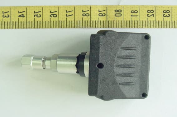
LJL040501T
Aug 01, 2004Tire Pressure Monitoring System
Equipment Class
DSC - Part 15 Security/Remote Control Transmitter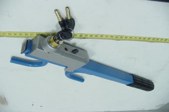
LJL030401T
May 01, 2003Wheel Lock Immobilizer ( Transmitter )
Equipment Class
DSC - Part 15 Security/Remote Control Transmitter