LJL040501TTire Pressure Monitoring System
Lite On Automotive Corporation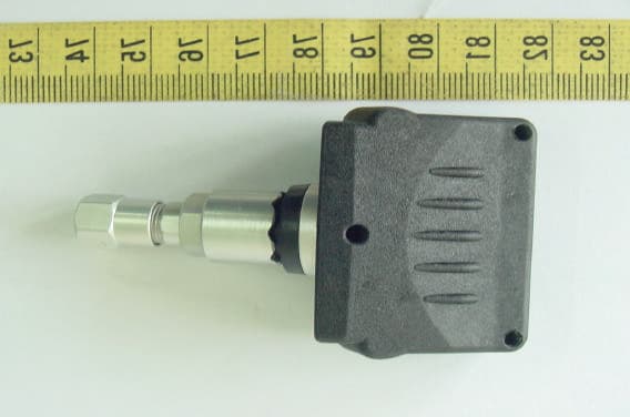
Click to zoom
Application Details
- Equipment Class
- DSC - Part 15 Security/Remote Control Transmitter
- Date of Grant
- Aug 01, 2004
- Application Purpose
- Original Equipment
- Date of Application
- Aug 01, 2004
- Equipment Note
- Tire Pressure Monitoring System
- Frequency Range
- 433.92000000 - 433.92000000
- Country
- Taiwan
Documents & Files
Document Text
Text extracted from the exhibit documents filed with the FCC. Open a document above to read the original.
Users Manual
TPM-100 (MTPM-100) specification Rev. 6 25 th May 2004 1 TPM-100 (MTPM-100) Product Description Kit content: 1. 4 Generation 1 Wheel sensors 2. Receiver 3. Display 4. 1 x 17cm Wire Antenna 5. 1 x 2.5 meter antenna 6. Wiring harness 7. Accessories Optional accessories: 1. 2 x Generation 1, Wheel Sensor Kit for 6 Wheel Vehicles 2. Generation 1 Wheel sensor 3. Valve (in separate items, as specified at “Wheel sensor”) Wheel sensor: • Specialized LITEON valve to be purchased from Record. 300-0087810 • Generation I sensor-unit (433.92 MHz) • Washer 215-0096300 • Slider accessory 200-0028140 The nut that holds the sensor-unit to the valve is fixed with a drop of LOCTITE 243 (Cat No. 18941). Receiver: The receiver should fit in a VS350/VS320 housing. Connectors accessible from the outside: • SMB connector (Snap On Coupling) 1 pcs. (Antenna) • MOLEX 70555, 3 pin connector 1 pcs. (Wiring harness) • MOLEX 70555, 4 pin connector 1 pcs. (Display) Display: • TPM-100 - A10-2489170 RX SW (IR switch with TPMS logo) • MTPM-100 - Waeco Specific ID Design Switch. • MOLEX 70066G, 4-pin connector (Terminals: MOLEX 70058-0022) The terminals should be connected to the wiring but the connector should be separate in the kit. This to enable a proper installation of the switch on the dashboard (as with IR-switch) Antenna: • 1 x 17cm flexible antenna and SMB connector (Snap On Coupling) • 1 x 2.5 meter flexible antenna and SMB connector antenna Wiring harness: • MOLEX 70066G, 3 pin connector & MOLEX 70058-0022 terminals. • 0.5- meter cable (2 pcs, red, orange and black) – Permanent Feed Connection on this system. • Separate fuse with 15cm of wiring on each end. (Not connected to main wiring harness!) Accessories: • 3 cable ties (5x430mm) • 1 double- sided pad (size of largest surface of the receiver-module) • 1 double- sided pre shaped pad (VST (Very Strong Tape) #6080G) for fixing display. TPM-100 (MTPM-100) specification Rev. 6 25 th May 2004 2 Functionality: Normal Operation Mode: As soon as the ignition is switched on, the system will perform a self-test. This self-test should take no longer than 108 seconds to be completed. The self-test period is defined as the period from the point that the ignition is switched on to the point that the Electronic Module receiver has received the latest Tire Conditions from each wheel taught to the system. If the system is permanently fed the signals are received when the ignition is switched off. As a result, the self-test period takes 2 seconds and then the latest Tire Conditions are displayed. During the first 2 seconds of the self-test period, the LED will turn on RED for 2 second and the buzzer will sound for 0.3 seconds. After this 2-second period, one of 3 sets of conditions will be displayed:- i) If all Tire Conditions were OK when the ignition was last switched off, then the LED will start to flash Green at a rate of 0.5 Seconds ON/0.5 Seconds OFF. If all Tire Conditions are still OK at the end of the self-test period, then the LED will turn Constant Green. ii) If all Tire Conditions were OK when the ignition was last switched off, then the LED will start to flash Green at a rate of 0.5 seconds ON/0.5 Seconds OFF. If Tire Condition information is received from a sensor indicting a Warning or Alert conditions (either Temperature or Pressure), then the LED will immediately indicate the detected Condition. Note : This should happen as soon as the information is receiver – do not wait until the end of the self-test period. iii) If Tire Conditions were not OK when the ignition was last switched off, then the LED should immediately display the relevant Tire Condition Warning or Alert. This Tire Conditions will continue to be displayed throughout the self-test period. At the end of the self-test period, the display will either change to indicate all tire conditions are now OK (LED on Green) if the problem has been rectified or to show the Tire Condition Warning or Alert if the conditions still exists. If the Tire Conditions of all tires are OK, the LED will light up Green and will turn-off after one minute (To avoid distraction/ irritation of the driver). When the button is pressed (LED is OFF), the LED will show the latest condition (To give the driver the feeling the system is still working). If no signal has been received from one sensor for more then 10 minutes (with the ignition on), the LED will change colour continuously indicating that the receiver is searching for a signal. (0.25 seconds green / 0.25 seconds orange / 0.25 seconds red / 0.25 seconds orange / etc.) TPM-100 (MTPM-100) specification Rev. 6 25 th May 2004 4 Tire Conditions: During the “Normal Operation Mode” the system will continuously check the condition of all tires. The conditions are then represented by 3 colors: Green Condition: The condition (pressure & temperature) of all tires is ok. (The tire pressure is between (>)75% and (<)150% of the Front or Rear Preset Pressure and the tire temperature is below 85°C.) Indication: The display (LED) will light up green and will turn off after 1 minute. Whenever the driver pushes the button, the display will show the current condition again. (And of course turn off again after 1 minute) Orange Condition: The pressure of one (or more) tires is 75% of the Front or Rear Preset Pressure or lower. Indication: The display (LED) will blink orange (0.2 seconds on, 0.8 seconds off) for one minute and beep in the same frequency for 15 seconds. The driver must be able turn off the beeping whenever he pushes the button. After this minute the LED will continuously light up orange. This complete procedure will be repeated only once again after 10 minutes. After this it will light up orange continuously. Red Conditions: The pressure of one (or more) tires is 50% of the Front or Rear Preset Pressure or lower. The pressure of one (or more) tires is 150% of the Front or Rear Preset Pressure or higher. The temperature is 85°C or higher. Indication: 1. The display (LED) will bl…
Text truncated - open the document above for the full version.
Cover Letter(s)
LITE-ON AUTOMOTIVE CORPORATION 37, Chung Yang Road, N.E.P.Z. Kauhsiung 811, Taiwan. R.O.C. Federal Communications Commission FCC ID: LJL040501T Dear Sir: This is to request confidentiality on information submitted for above application. We would like to request confidentiality on some exhibits we submitted for above original application for the reason of trade secret. If those exhibits are available for public inspection, any person who once gets the information contained in those exhibits will be able to design and to make the same products very easily. This is a very serious problem and huge loss for us, because we did invest so much on it. Please be not made the Exhibit Types listed below routinely available for public inspection: Block Diagram and Schematics. By: By: C. F. Huang (Signature) (Printed) Title : President Applicant : LITE-ON AUTOMOTIVE CORPORATION Address : 37, Chung Yang Road, N.E.P.Z. Kauhsiung 811, Taiwan. R.O.C. Tel : 886-7-3611111 Fax:886-7-3613627 Date : 2004-06-04
Cover Letter(s)
1 Mike Kuo From: SS [[email protected]] Sent: July302004Friday 1:48 AM To: Mike Kuo Cc: R00/ Subject: Re: LITE-ON AUTOMOTIVE CORPORATION, FCC ID: LJL040501T, Assessment NO.: AN04T4034, Notice#1 Exhibit-C-Test_Rep ort_Revise.p... Dear Mike, Please find revised test report. Best regards, ================================ S. S. Liou Engineer / EMC Dept. II Electronics Testing Center, Taiwan ----- Original Message ----- From: "Mike Kuo" <[email protected]> To: "'SS'" <[email protected]>; "Mike Kuo" <[email protected]> Cc: "R00/ 2
External Photos
ETC Report No.:ET93R-05-069-01 FCC ID.: LJL040501T Rev. No 1.0 CONSTRUCTED PHOTOS of EUT Top View of EUT Bottom View of EUT ETC Report No.:ET93R-05-069-01 FCC ID.: LJL040501T Rev. No 1.0 CONSTRUCTED PHOTOS of EUT Front View of EUT Rear View of EUT ETC Report No.:ET93R-05-069-01 FCC ID.: LJL040501T Rev. No 1.0 CONSTRUCTED PHOTOS of EUT Side View of EUT Side View of EUT
ID Label/Location Info
This statement will be placed in User’s Manual: This device complies with part 15 of the FCC Rules. Operation is subject to the following two conditions: 1.This device may not cause harmful interference. 2.This device must accept any interference received, including interference that may cause undesired operation. Model:TPM100 FCC ID:LJL040501T 42.00mm 8.00mm
Internal Photos
ETC Report No.:ET93R-05-069-01 FCC ID.: LJL040501T Rev. No 1.0 CONSTRUCTED PHOTOS of EUT Internal View of EUT ETC Report No.:ET93R-05-069-01 FCC ID.: LJL040501T Rev. No 1.0 CONSTRUCTED PHOTOS of EUT Component View of Main PCB Solder View of Main PCB
Operational Description
1. Normal Mode : When the tire pressure is normal, the transmitter will transmit a 10ms signal in 54.6 seconds time interval for polling the system intrgrity. 2. Alarm Mode : When 3 PSI tire pressure down is detected, the transmitter will transmit a 10ms signal which contains alarm codes in every 54.6 seconds.
Test Report
Rev. No 1.0 FCC Part 15 EMI TEST REPORT of E.U.T. : Tire Pressure Monitoring System (Transmitter) FCC ID. : LJL040501T MODEL : TPM100 Working Frequency : 433.92 MHz for APPLICANT : LITE-ON AUTOMOTIVE CORPORATION ADDRESS : 37,Chung Yang Road, N.E.P.Z. Kaohsiung 811, Taiwan. R.O.C. Test Performed by ELECTRONICS TESTING CENTER, TAIWAN NO. 34, LIN 5, DING FU TSUN, LINKOU HSIANG TAIPEI HSIEN, TAIWAN, R.O.C. Tel : (02)26023052 Fax : (02)26010910 http://www.etc.org.tw ; e-mail: [email protected] Report Number : ET93R-05-069-01 ETC Report No.:ET93R-05-069-01 FCC ID.: LJL040501T Rev. No 1.0 TEST REPORT CERTIFICATION Applicant : LITE-ON AUTOMOTIVE CORPORATION 37,Chung Yang Road, N.E.P.Z. Kaohsiung 811, Taiwan. R.O.C. Manufacturer : LITE-ON AUTOMOTIVE CORPORATION 37,Chung Yang Road, N.E.P.Z. Kaohsiung 811, Taiwan. R.O.C. Description of EUT : a) Type of EUT : Tire Pressure Monitoring System(Transmitter) b) Trade Name : ---- c) Model No. : TPM100 d) FCC ID : LJL040501T e) Working Frequency : 433.92 MHz f) Power Supply : DC 3V Battery Regulation Applied : FCC Rules and Regulations Part 15 Subpart C (2003) I HEREBY CERTIFY THAT; The data shown in this report were made in accordance with the procedures given in ANSI C63.4 and the energy emitted by the device was founded to be within the limits applicable. I assume full responsibility for accuracy and completeness of these data. Note : 1. The results of the testing report relate only to the items tested. 2. The testing report shall not be reproduced except in full, without the written approval of ETC. Issued Date : Jun. 25, 2004 Test Engineer : ( Vincent Chang ) Approve & Authorized Signer : Will Yauo, Manager EMC Dept. II of ELECTRONICS TESTING CENTER, TAIWAN ETC Report No.:ET93R-05-069-01 FCC ID.: LJL040501T Rev. No 1.0 Table of Contents Page 1. GENERAL INFORMATION.....................................................................................................................................................1 1.1 PRODUCT DESCRIPTION...........................................................................................................................................................1 1.2 CHARACTERISTICS OF DEVICE:...............................................................................................................................................1 1.3 TEST METHODOLOGY..............................................................................................................................................................1 1.4 TEST FACILITY..........................................................................................................................................................................1 2. DEFINITION AND LIMITS.......................................................................................................................................................2 2.1 DEFINITION................................................................................................................................................................................2 2.2 RESTRICTED BANDS OF OPERATION.....................................................................................................................................2 2.3 LIMITATION...............................................................................................................................................................................2 2.4 LABELING REQUIREMENT.......................................................................................................................................................4 2.5 USER INFORMATION.................................................................................................................................................................4 3 SYSTEM TEST CONFIGURATION.........................................................................................................................................5 3.1 JUSTIFICATION..........................................................................................................................................................................5 3.2 DEVICES FOR TESTED SYSTEM...............................................................................................................................................5 4. RADIATED EMISSION MEASUREMENT.............................................................................................................................6 4.1 APPLICABLE STANDARD.........................................................................................................................................................6 4.2 MEASUREMENT PROCEDURE..................................................................................................................................................6 4.3 TEST DATA.................................................................................................................................................................................8 4.4 FIELD STRENGTH CALCULATION........................................................................................................................................10 4.5 ACTIVATE TIME......................................................................................................................................................................10 4.6 CALCULATION OF DUTY FACTOR.......................................................................................................................................10 4.7 RADIATED TEST EQUIPMENT...............................................................................................................................................13 4.8 MEASURING INSTRUMENT SETUP.......................................................................................................................................13 4.9 RADIATED MEASUREMENT PHOTOS...............................................................................…
Text truncated - open the document above for the full version.
Test Setup Photos
ETC Report No.:ET93R-05-069-01 FCC ID.: LJL040501T Rev. No 1.0 Radiated Measurement Photos
Contact Information
Applicant
Steven Yang(Senior Engineer)
Test Firm
Electronics Testing Center, TaiwanWill Yauo
Technical Specifications
| # | Rule Parts | Frequency Range | Power Output |
|---|---|---|---|
| 1 | 15.231(e) | 433.92 MHz - 433.92 MHz | - |
Other Applications from Lite On Automotive Corporation
LJLCM22
Apr 27, 2014Remote control
Equipment Class
DSC - Part 15 Security/Remote Control Transmitter
LJL07022801
Mar 07, 2007Remote Control Transmitter
Equipment Class
DSC - Part 15 Security/Remote Control Transmitter
LJL041201T
Mar 10, 2005Tire Pressure Monitor System
Equipment Class
DSC - Part 15 Security/Remote Control Transmitter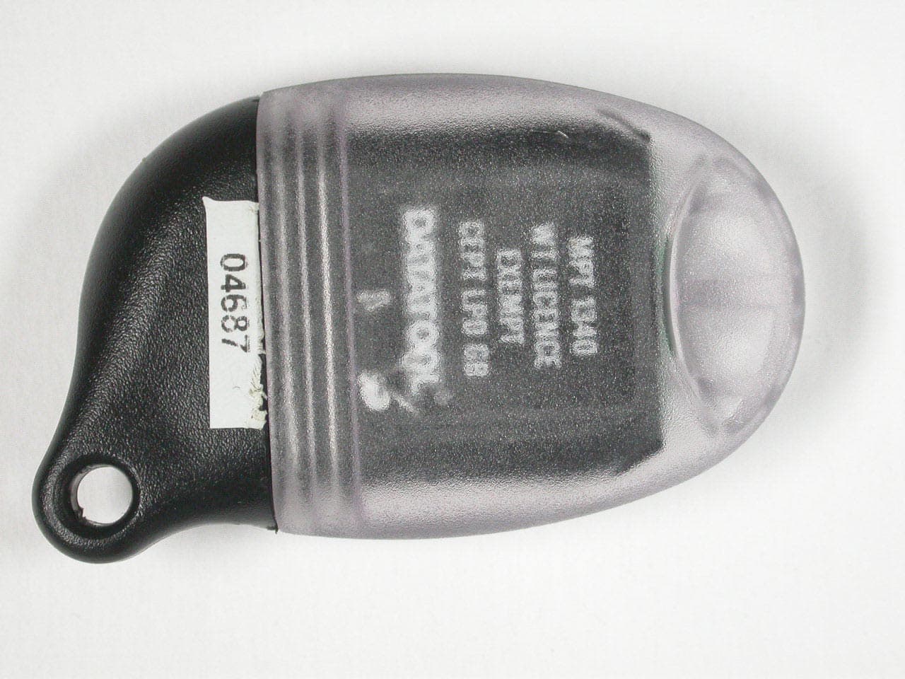
LJL02011032
Nov 25, 2003Remote Control Transmitter
Equipment Class
DSC - Part 15 Security/Remote Control Transmitter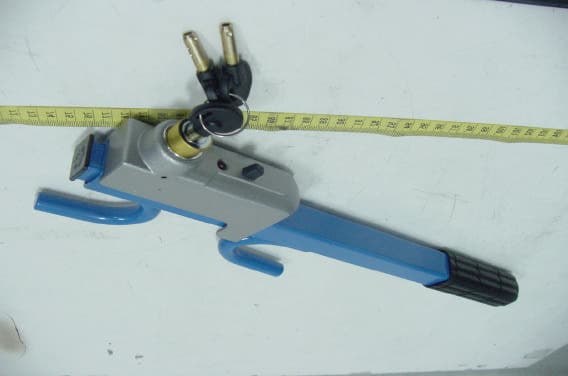
LJL030401T
May 01, 2003Wheel Lock Immobilizer ( Transmitter )
Equipment Class
DSC - Part 15 Security/Remote Control Transmitter