LJLCM22Remote control
Lite On Automotive Corporation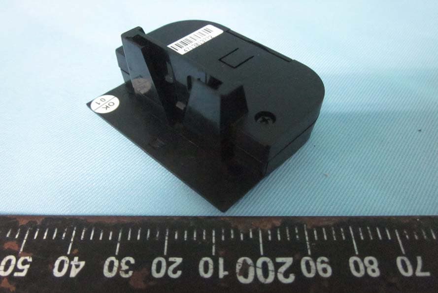
Click to zoom
Application Details
- Equipment Class
- DSC - Part 15 Security/Remote Control Transmitter
- Date of Grant
- Apr 27, 2014
- Application Purpose
- Original Equipment
- Date of Application
- Apr 27, 2014
- Equipment Note
- Remote control
- Frequency Range
- 433.85600000 - 433.85600000
- Country
- Taiwan
Documents & Files
Document Text
Text extracted from the exhibit documents filed with the FCC. Open a document above to read the original.
Users Manual
CM22 434MHz R.F. Steering Hub Switch Dealers address details: 1. Kit Contents 2. Installation IMPORTANT SAFETY CAUTION IF IT IS NECESSARY DISARM OR REMOVE AN SRS AIRBAG, MANUFACTURER’S PROCEDURE MUST BE FOLLOWED. FAILURE TO DO SO MAY RESULT IN AIRBAG DEPLOYMENT AND POSSIBLE INJURY OR DAMAGE TO VEHICLE. INSTALLATION PROCEDURE NOTES—The switch must be fitted to the right side of the steering wheel as the buttons are not reversible. The battery supplied in the hardware is a spare to be given to the owner of the vehicle. The switch already contains a long life battery. Mount the “Cruise Engage“ LED (small white LED with black-sheathed 3 wire harness) in a location on the dashboard where it can be seen by the driver. Mount the oval “CRUISE “ decal and secure the LED with small black plastic retaining grommet. Mount the interface module in an appropriate location (i.e. behind dashboard) and connect the LED with 3 wire harness. CAUTION! Do not connect to a powered harness. Ensure all connections are complete before supplying power or testing operation. Plug cruise engage LED harness (red, yellow and green wires in white plug) into 3 pin white socket right side on the interface module. Switch harness (6 wires in short harness, flat white plug and 2 row clear plug). Connect flat white plug into 6 pin white socket on the interface module, and clear 2 row plug into switch socket on main cruise control wiring harness. SWITCH INSTALLATION IS NOW COMPLETE The cruise engage LED will show a dull glow when Cruise Control is off and ignition switch is on. This will assist the LED location during night time driving. Note: The red LED indicator in the middle of transmitter module will illuminate when any button is pressed. It will flash with 5 times when it is at low battery condition. You have to replace battery as soon as possible (Spare battery supplied – model CR2032). 3.Learn transmitter module The CM22 transmitter module and interface module is matched after production. If you want to relearn that for any reason, please perform the procedure as following. 1.Power off the interface module 2.Make short on pin 1 and 2 or pin 2 and 3 of the interface module connector. 3.Press and hold on/off button of the transmitter module. 4.Power on the interface module. 4.The CM22 module complies with the following: Notice : The changes or modifications not expressly approved by the party responsible for compliance could void the user’s authority to operate the equipment. IMPORTANT NOTE: To comply with the FCC RF exposure compliance requirements, no change to the antenna or the device is permitted. Any change to the antenna or the device could result in the device exceeding the RF exposure requirements and void user’s authority to operate the device. 5. USER GUIDE LED INDICATOR FUNCTIONS There are 2 LED lights, one on the switch body below the ON/OFF button, and the other mounted on the vehicle dashboard, with a black disc displaying the word CRUISE. The SWITCH LED will flash whenever a button is pressed. It will also flash 5 times when the internal battery requires replacement. The battery type is a long-life CR2032 type, and should last for several years in normal operation. It should be replaced without delay when the 5-flash signal is shown, as the Cruise Control will cease to operate when the battery has lost charge. The DASHBOARD LED is the Cruise Control status indicator. It will display a dull pink colour when switched OFF to assist in locating the LED. When the Cruise Control is switched ON (but not engaged) This device complies with Part 15 of the FCC Rules. Operation is subject to the following two conditions: (1) this device may not cause harmful interference, and (2) this device must accept any interference received, including interference that may cause undesired operation. the LED will display a Green colour, when ENGAGED it will display an Orange colour. ON/OFF BUTTON This button turns the Cruise Control ON or OFF. Status LED will change colour as detailed above. SET/ACC BUTTON (Set/Accelerate Functions) This button has 2 functions. When the Cruise Control is in standby (Green LED) pressing this button will SET (engage) the Cruise Control at your current speed. When the Cruise Control is engaged (Orange LED) pressing this button will ACCELERATE (increase) the speed. One brief press will increase speed by 1kph. On AP300 and AP500 models pressing and holding the button will increase speed in a gentle and progressive manner, holding the higher speed when the button is released. On AP900 and AP900C models pressing and holding the button for approx 1.5-2 seconds will increase speed by 10kph above current set speed. This is indicated by 2 brief beep tones when holding the SET/ACC button for the required period. RES/DEC BUTTON (Resume/Decelerate Functions) The RESUME function allows you to return to your last SET speed. If you have applied the brakes to disengage the Cruise Control (such as travelling through a small country town with lower speed limit), pressing the RES button will return the vehicle to the last SET speed on the current journey. If the Cruise Control or Ignition has been turned OFF this feature will not operate as the last speed memory setting has been erased. When the Cruise Control is engaged (Orange LED) it will decelerate the vehicle. One brief press will decrease speed by 1kph. On AP300 and AP500 models pressing and holding the button will decrease speed in a gentle and progressive manner, holding the lower speed when the button is released. On AP900 and AP900C models pressing and holding the button for approx 1.5-2 seconds will decrease speed by 10kph below current set speed. Again, 2 brief 2 beep tones will confirm 10kph reduction is activated. IMPORTANT NOTE – The rate of vehicle deceleration can vary according to several factors including going down long or steep gradients, towing, carrying loads etc. The Cruise Control cannot apply the vehicle brakes, and the vehicle driver should …
Text truncated - open the document above for the full version.
Cover Letter(s)
LITE-ON Automotive Corporation 37 Chung Yang Road, N.E.P.Z. Kaohsiung 811, Taiwan (R.O.C.) Date: March 21,2014 Federal Communications Commission 7435 Oakland Mills Road Columbia MD 21046 c.c. UL Verification Services Certification Division 47173 Benicia Street Fremont, CA 94538, USA To whom it may concern: I, the undersigned, hereby authorize ELECTRONICS TESTING CENTER, TAIWAN, and hereafter referred to as ETC, to act on our behalf in all manners relating to application for equipment authorization, including signing of all documents relating to these matters. Any and all acts carried out by ELECTRONICS TESTING CENTER, TAIWAN, on our behalf shall have the same effect as acts of our own. I, the undersigned, hereby certify that we are not subject to a denial of federal benefits, that includes FCC benefits, pursuant to Section 5301 of the Anti-Drug Abuse Act of 1988, 21 U.S.C. 853(a). In authorizing ETC as our agent, we still recognize that we are responsible to: a) comply with the relevant provisions of the certification program; b) make all necessary arrangements for the conduct of the evaluation, including provision for examining documentation and access to all areas, records (including internal audit reports) and personnel for the purposes of evaluation (e.g. testing, inspection, assessment, surveillance, reassessment) and resolution of complaints; c) make claims regarding certification only in respect of the scope for which certification has been granted; d) do not use our product certification in such a manner as to bring the Certification Division into disrepute and not make any statement regarding our product certification which the Certification Division may consider misleading or unauthorized; e) upon suspension or cancellation of certification, discontinue use of all advertising matter that contains any reference thereto and return any certification documents as required by the Certification Division; f) use certification only to indicate the products are certified as being in conformity with specified standards; g) endeavor to ensure that no certificate or report nor any part thereof is used in a misleading manner; h) ensure that any reference to our product certification in communication media such as documents, brochures or advertising, complies with the requirements of the Certification Division; i) keep a record of all complaints made known to the us relating to the product’s compliance with requirements of the relevant standard and to make these records available to the Certification Division when requested; j) take appropriate action with respect to such complaints and any deficiencies found in products or services that affect compliance with the requirements for certification; k) document the actions taken. This authorization is valid until further written notice from the applicant. Sincerely Yours, Senior Engineer Steven Yang LITE-ON Automotive Corporation REMARK: 1. This authorization letter will be sent along with your application when filing with the Certification Division. 2. Please follow the format and type it on company letterhead and send original to us. 3. Authorized signature must be in agreement with grantee code contact in FCC database.
Cover Letter(s)
LITE-ON Automotive Corporation 37 Chung Yang Road, N.E.P.Z. Kaohsiung 811, Taiwan (R.O.C.) Date: March 21,2014 Federal Communications Commission 7435 Oakland Mills Road Columbia MD 21046 Subject: Request for Confidentiality FCC ID: LJLCM22 To Whom It May Concern: Pursuant to the provisions of Sections 0.457 and 0.459 of the Commission’s rules (47 CFR §§ 0.457, 0.459), we are requesting the Commission to withhold the following attachments as confidential document from public disclosure indefinitely. Schematic Diagram Block Diagram Theory of Operation Above mentioned document contains detailed system and equipment description are considered as proprietary information in operation of the equipment. The public disclosure of above documents might be harmful to our company and would give competitor an unfair advantage in the market. It is our understanding that all measurement test reports, FCC ID label format and correspondent during certification review process cannot be granted as confidential documents and those information will be available for public review once the grant of equipment authorization is issued. Best Regards Senior Engineer Steven Yang March 21, 2014
External Photos
ETC Report No.:14-01-RBF-043-01 Sheet 1 of 4 Sheets FCC ID.: LJLCM22 Rev. No 1.0 CONSTRUCTED PHOTOS of EUT 1. 2. ETC Report No.:14-01-RBF-043-01 Sheet 2 of 4 Sheets FCC ID.: LJLCM22 Rev. No 1.0 CONSTRUCTED PHOTOS of EUT 3. 4.
ID Label/Location Info
Label Here FCC ID:LJLCM22 25 mm x 5 mm
Internal Photos
ETC Report No.:14-01-RBF-043-01 Sheet 3 of 4 Sheets FCC ID.: LJLCM22 Rev. No 1.0 CONSTRUCTED PHOTOS of EUT 5. 6. ETC Report No.:14-01-RBF-043-01 Sheet 4 of 4 Sheets FCC ID.: LJLCM22 Rev. No 1.0 CONSTRUCTED PHOTOS of EUT 7. 8.
Test Report
Rev. No 1.0 FCC Part 15 EMI TEST REPORT of E.U.T. : CM22 RF C/M FCC ID : LJLCM22 MODEL : CM22 Workin g Frequency : 433.856 MHz for APPLICANT : LITE-ON Automotive Corporation ADDRESS : 37 Chung Yang Road, N.E.P.Z. Kaohsiung 811, Taiwan (R.O.C.) Test Performed by ELECTRONICS TESTING CENTER, TAIWAN NO. 34. LIN 5, DINGFU VIL., LINKOU DIST., NEW TAIPEI CITY, TAIWAN, 24442, R.O.C. TEL : (02)26023052 Fax : (02)26010910 http://www.etc.org.tw ; e-mail: [email protected] Report Number : 14-01-RBF-043-01 ETC Report No.14-01-RBF-043-01 FCC ID.: LJLCM22 Rev. No 1.0 TEST REPORT CERTIFICATION Applicant : LITE-ON Automotive Corporation 37 Chung Yang Road, N.E.P.Z. Kaohsiung 811, Taiwan (R.O.C.) Manufacturer : LITE-ON Automotive Corporation 37 Chung Yang Road, N.E.P.Z. Kaohsiung 811, Taiwan (R.O.C.) Description of EUT : a) Type of EUT : CM22 RF C/M b) Trade Name : LITEON, BDI c) Model No. : CM22 d) FCC ID : LJLCM22 e) Working Frequency : 433.856 MHz f) Power Supply : Battery 3V Regulation Applied : FCC Rules and Regulations Part 15 Subpart C I HEREBY CERTIFY THAT; The data shown in this report were made in accordance with the procedures given in ANSI C63.4 (2003) and the energy emitted by the device was founded to be within the limits applicable. I assume full responsibility for accuracy and completeness of these data. Note : 1. The results of the testing report relate only to the items tested. 2. The testing report shall not be reproduced except in full, without the written approval of ETC. Summary of Tests Test Results Radiated Emission Pass Bandwidth of Emision Pass Conducted Emission N/A ETC Report No.14-01-RBF-043-01 FCC ID.: LJLCM22 Rev. No 1.0 Issued Date : Apr. 14, 2014 Test Engineer : (Tien-Lu Liao , Engineer ) Approve & Authorized Signer : S. S. Liou, Section Manager EMC Dept. II of ELECTRONICS TESTING CENTER, TAIWAN ETC Report No.14-01-RBF-043-01 FCC ID.: LJLCM22 Rev. No 1.0 Table of Contents Page 1. GENERAL INFORMATION ............................................................................................................................... 1 1.1 PRODUCT DESCRIPTION........................................................................................................................................... 1 1.2 CHARACTERISTICS OF DEVICE:................................................................................................................................ 1 1.3 TEST METHODOLOGY.............................................................................................................................................. 1 1.4 TEST FACILITY........................................................................................................................................................ 1 2. DEFINITION AND LIMITS ................................................................................................................................ 2 2.1 DEFINITION............................................................................................................................................................. 2 2.2 RESTRICTED BANDS OF OPERATION........................................................................................................................ 2 2.3 LIMITATION............................................................................................................................................................. 2 2.4 LABELING REQUIREMENT........................................................................................................................................ 4 2.5 USER INFORMATION................................................................................................................................................ 4 3 SYSTEM TEST CONFIGURATION ................................................................................................................... 5 3.1 JUSTIFICATION........................................................................................................................................................ 5 3.2 DEVICES FOR TESTED SYSTEM................................................................................................................................5 4. RADIATED EMISSION MEASUREMENT ...................................................................................................... 6 4.1 APPLICABLE STANDARD.......................................................................................................................................... 6 4.2 MEASUREMENT PROCEDURE................................................................................................................................... 6 4.3 TEST DATA.............................................................................................................................................................. 8 4.4 FIELD STRENGTH CALCULATION........................................................................................................................... 11 4.5 ACTIVATE TIME.................................................................................................................................................... 11 4.6 CALCULATION OF DUTY FACTOR.......................................................................................................................... 11 4.7 RADIATED TEST EQUIPMENT................................................................................................................................. 17 4.8 MEASURING INSTRUMENT SETUP.......................................................................................................................... 17 4.9 RADIATED MEASUREMENT PHOTOS...................................................................................................................... 18 5. BANDWIDTH OF EMISSION........................................................................................................................... 19 5.1 APPLICABLE STANDARD PLOT GRAPHIC OF BANDWIDTH.........…
Text truncated - open the document above for the full version.
Test Setup Photos
ETC Report No.:14-01-RBF-043-01 Sheet 18 of 22 Sheets FCC ID.: LJLCM22 Rev. No 1.0 4.9 Radiated Measurement Photos
Contact Information
Applicant
Steven Yang(Senior Engineer)
Test Firm
Taiwan Testing and Certification CenterAnderson Ku
Technical Specifications
| # | Rule Parts | Frequency Range | Power Output |
|---|---|---|---|
| 1 | 15.231 | 433.856 MHz - 433.856 MHz | - |
Other Applications from Lite On Automotive Corporation
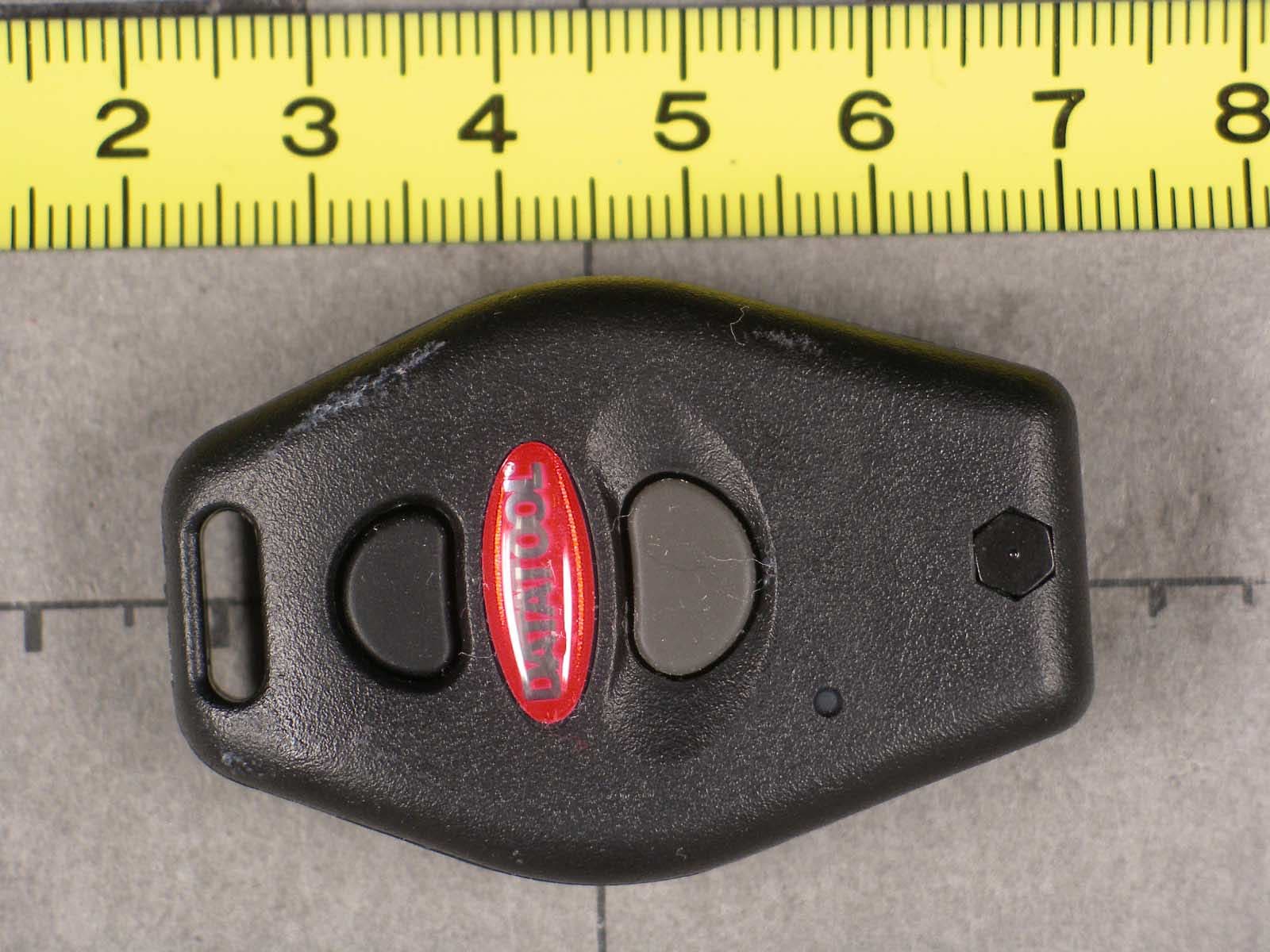
LJL07022801
Mar 07, 2007Remote Control Transmitter
Equipment Class
DSC - Part 15 Security/Remote Control Transmitter
LJL041201T
Mar 10, 2005Tire Pressure Monitor System
Equipment Class
DSC - Part 15 Security/Remote Control Transmitter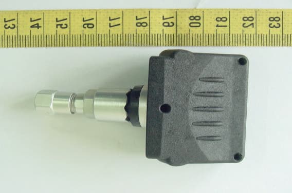
LJL040501T
Aug 01, 2004Tire Pressure Monitoring System
Equipment Class
DSC - Part 15 Security/Remote Control Transmitter
LJL02011032
Nov 25, 2003Remote Control Transmitter
Equipment Class
DSC - Part 15 Security/Remote Control Transmitter
LJL030401T
May 01, 2003Wheel Lock Immobilizer ( Transmitter )
Equipment Class
DSC - Part 15 Security/Remote Control Transmitter