LJPNPL-4GSM 850/1800/1900 Cellular Telephone
Microsoft Corporation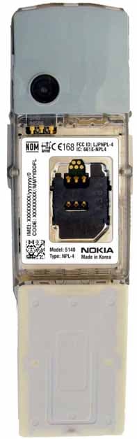
Click to zoom
Application Details
- Equipment Class
- PCE - PCS Licensed Transmitter held to ear
- Date of Grant
- Mar 27, 2004
- Application Purpose
- Original Equipment
- Date of Application
- Mar 27, 2004
- Equipment Note
- GSM 850/1800/1900 Cellular Telephone
- Frequency Range
- 824.20000000 - 848.80000000
- Company
- Microsoft Corporation
- Country
- United States
Documents & Files
Document Text
Text extracted from the exhibit documents filed with the FCC. Open a document above to read the original.
Users Manual
Nokia 5140 User's Guide 999999 1. Issue Antenna House XSL Formatter (Evaluation) http://www.antennahouse.com/ DECLARATION OF CONFORMITY We, NOKIA CORPORATION declare under our sole responsibility that the product npl-5 is in conformity with the provisions of the following Council Directive: 1999/5/EC. A copy of the Declaration of Conformity can be found from www.nokia.com/phones/declaration_of_conformity/. EXPORT CONTROLS This device may contain commodities, technology, or software that may only be exported in accordance with the U. S. Export Administration regulations. Diversion contrary to U.S. or Canadian law is prohibited. FCC/INDUSTRY CANADA NOTICE Your device may cause TV or radio interference (for example, when using a telephone in close proximity to receiving equipment). The FCC or Industry Canada can require you to stop using your telephone if such interference cannot be eliminated. If you require assistance, contact your local service facility. This device complies with part 15 of the FCC rules. Operation is subject to the condition that this device does not cause harmful interference. Copyright © 2004 Nokia. All rights reserved. Reproduction, transfer, distribution or storage of part or all of the contents in this document in any form without the prior written permission of Nokia is prohibited. Reproduction, transfer, distribution or storage of part or all of the contents in this document in any form without the prior written permission of Nokia is prohibited. Nokia, Nokia Connecting People, Xpress-on and Pop-port are trademarks or registered trademarks of Nokia Corporation. Other product and company names mentioned herein may be trademarks or tradenames of their respective owners. Nokia tune is a sound mark of Nokia Corporation. US Patent No 5818437 and other pending patents. T9 text input software Copyright (C) 1997-2004. Tegic Communications, Inc. All rights reserved. Includes RSA BSAFE cryptographic or security protocol software from RSA Security. Java is a trademark of Sun Microsystems, Inc. USE OF THIS PRODUCT IN ANY MANNER THAT COMPLIES WITH THE MPEG-4 VISUAL STANDARD IS PROHIBITED, EXCEPT FOR USE DIRECTLY RELATED TO (A) DATA OR INFORMATION (i) GENERATED BY AND OBTAINED WITHOUT CHARGE FROM A CONSUMER NOT THEREBY ENGAGED IN A BUSINESS ENTERPRISE, AND (ii) FOR PERSONAL USE ONLY; AND (B) OTHER USES SPECIFICALLY AND SEPARATELY LICENSED BY MPEG LA, L.L.C. Under no circumstances shall Nokia be responsible for any loss of data or income or any special, incidental, consequential or indirect damages howsoever caused. Antenna House XSL Formatter (Evaluation) http://www.antennahouse.com/ The contents of this document are provided "as is". Except as required by applicable law, no warranties of any kind, either express or implied, including, but not limited to, the implied warranties of merchantability and fitness for a particular purpose, are made in relation to the accuracy, reliability or contents of this document. Nokia reserves the right to revise this document or withdraw it at any time without prior notice The availability of particular products may vary by region. Please check with the Nokia dealer nearest to you. 999999/1. Issue Antenna House XSL Formatter (Evaluation) http://www.antennahouse.com/ Contents For your safety.........................6 ABOUT YOUR DEVICE................................7 NETWORK SERVICES.................................7 Shared memory.......................................8 1. Getting started..................... 9 Installing the SIM card and battery........................................................9 Charging the battery...........................11 Switching the phone on and off.............................................................. 12 Keys and connectors...........................14 Main indicators in standby mode........................................................ 15 Access codes..........................................16 Changing the shell and key mat............................................................ 17 Attaching the carrying strap to the phone.......................................................19 2. Your phone.........................20 Standby mode.......................................20 Keypad lock (Keyguard).....................21 Over the air settings service.............22 3. Call functions......................23 Making a call..........................................23 Speed dialling........................................23 Answering or rejecting a call...........23 Options during a call...........................24 4. Menu functions..................26 Using the menu....................................26 Menu list..................................................28 5. Writing text........................30 Setting predictive text input on and off.....................................................30 Selecting the writing language.................................................30 Using predictive text input...............30 Using traditional text input..............31 Tips for writing text............................32 6. Messages............................. 34 Text messages.......................................34 Multimedia messages.........................37 E-mail messages...................................41 Instant messaging .............44 Voice messages.....................................55 Message settings..................................55 Service commands...............................57 7. Call log.................................58 Recent call lists......................................58 Call counters and call timers............58 8. Contacts............................... 59 Settings for contacts...........................59 Adding contacts....................................59 Saving multiple numbers and text items........................................................ 60 Adding an image..................................61 Searching for a contact......................61 Editing or …
Text truncated - open the document above for the full version.
Cover Letter(s)
NOKIA CORPORATION Nokia Mobile Phones Elektroniikkatie 10 FIN-90570 OULU FINLAND Tel. +358 7180 08000 Fax. +358 7180 47222 February 10, 2004 Federal Communications Commission, Authorization & Evaluation Division, 7435 Oakland Mills Road, Columbia, MD. 21046 Attention: Equipment Authorization Branch REQUEST FOR CONFIDENTIALITY Pursuant to Sections 0.457 (d) (l) (ii) and 0.459 of the Commission’s Rules, the Applicant hereby requests confidential treatment of some of the information accompanying this Application of FCC ID: LJPNPL-4 and as outlined below: - Exhibit 4: Block Diagram - Exhibit 5: Schematic Diagrams - Exhibit 10: List of Active Devices and Tune-Up Procedure - Exhibit 12: Theory of Operation / Description of Circuitry These materials contain trade secrets and proprietary information not customarily released to the public and the public disclosure of these matters might be harmful to the Applicant and provide unjustified benefits to its competitors. The Applicant understands that pursuant to Rule 0.457 (d) (l) (ii) disclosure of this Application and all accompanying documentation will not be made before the date of the Grant for this Application. NOKIA CORPORATION Pekka Väyrynen Product Program Manager Multimedia, Oulu
Cover Letter(s)
Kare Oksanen 04/26/2004 Applicant: Nokia Corporation Correspondence Reference Number: 12094 731 Confirmation Number: TC194111 Date of Original Email: 04/23/2004 Subject: Request for additional information 1) Please clarify if the 1900 MHz band mode can have 1 or 2 time slots. Clarify the corresponding state of radiated power measurement on page 9 of 49 of EMC report. Provide data for the other time slot condition as appropriate. Provide SAR data for both conditions as appropriate. GSM1900 has also 2-time slot mode available, but to answer this question, please see Exhibit 10: tune-up procedure section 2.3.5 for background information. This explains, why in GPRS850 mode both time slot conditions were measured, but in GPRS1900 mode results in EMC report represent them both, and in SAR report only 2-time slot condition was used. 2) SAR report states that tests codes were used to control the device. Please provide details of power setting to assure that the device was operating at the same power during EMC testing. We use special control software to operate device under desired mode, band, frequency and power level. After selected operating mode and band, this software provides drop-down list of all available power levels in selected mode/band, in which highest is selected both in SAR and EMC testing. 3) Please provide SAR results for all modes for all test configurations in accordance with Supplement C and PN 02 1438. In particular GSM 850 but also EGPRS modes. In Supplement C 01-01 ‘Device operating modes’ section it is said ‘For devices that operate in multiple modes within the same frequency band, all modes with a maximum source-based time-averaged output within 1.0 dB of the mode with the highest output should be tested to demonstrate compliance.’ Please refer to both EMC report page 9 of 49 and tune-up procedure sections 2.3.4 and 2.3.5 to compare power output in these modes to justify why EGPRS mode was not measured. At the time of our first EGPRS product, EGPRS mode was measured as well, and no significant difference between EGPRS/GSM was noticed after power output/used time slot differences were compensated. Please see our earlier application FCC ID: LJPNPL-3. Therefore, we still trust that we have already provided SAR results according to FCC guidelines in Supplement C.
External Photos
26 Mar 2004 External Photographs FCC ID: LJPNPL-4 Exhibit 3 IC: 661E-NPL4 Applicant: Nokia Corporation Copyright © 2004 Nokia. All rights reserved. 26 Mar 2004 External Photographs FCC ID: LJPNPL-4 Exhibit 3 IC: 661E-NPL4 Applicant: Nokia Corporation Copyright © 2004 Nokia. All rights reserved.
ID Label/Location Info
Label Location Exhibit 1 Applicant: Nokia Corporation FCC ID: LJPNPL-4 IC: 661E-NPL4 Copyright2004 Nokia. All Rights Reserved. 24 Mar 2004 168 FCC ID: LJPNPL-4 IC: 661E-NPL4 Model: 5140 Type: NPL-4 Made in Korea CODE: XXXXXXXX//MMYYDDFL IMEI: XXXXXXXX/yyyyyy/0 168 FCC ID: LJPNPL-4 IC: 661E-NPL4 Model: 5140 Type: NPL-4 Made in Korea CODE: XXXXXXXX//MMYYDDFL IMEI: XXXXXXXX/yyyyyy/0 XXXXXXX//MMYYDDFL Code: IMEI: XXXXXXXX/yyyyyy/0 Label Exhibit 1 Applicant: Nokia Corporation FCC ID: LJPNPL-4 IC: 661E-NPL4 Copyright2004 Nokia. All Rights Reserved. 24 Mar 2004 NOKIA CORPORATION Nokia Mobile Phones Elektroniikkatie 10 FIN-90570 OULU FINLAND Tel. +358 7180 08000 Fax. +358 7180 47222 February 10, 2004 Federal Communications Commission, Authorization & Evaluation Division, 7435 Oakland Mills Road, Columbia, MD. 21046 Attention: Equipment Authorization Branch COMPLIANCE STATEMENT OF LJPNPL-4 The compliance statement can be seen in User Guide of LJPNPL-4 because the size of the handportable LJPNPL-4 and its identification label are so small that the compliance statement cannot be printed visible enough. NOKIA CORPORATION Pekka Väyrynen Product Program Manager Multimedia, Oulu
Internal Photos
26 Mar 2004 Internal Photographs FCC ID: LJPNPL-4 Exhibit 9 IC: 661E-NPL-4 Applicant: Nokia Corporation Copyright © 2004 Nokia. All rights reserved. 26 Mar 2004 Internal Photographs FCC ID: LJPNPL-4 Exhibit 9 IC: 661E-NPL-4 Applicant: Nokia Corporation Copyright © 2004 Nokia. All rights reserved. 26 Mar 2004 Internal Photographs FCC ID: LJPNPL-4 Exhibit 9 IC: 661E-NPL-4 Applicant: Nokia Corporation Copyright © 2004 Nokia. All rights reserved.
RF Exposure Info
Oulu SAR Report 040-001708-EN Applicant: Nokia Corporation Type: NPL-4 Copyright 2004 TCC Oulu 2/22 CONTENTS 1. SUMMARY OF SAR TEST REPORT............................................................................................................................................. 4 1.1 TEST DETAILS.............................................................................................................................................................................4 1.2 MAXIMUM RESULTS....................................................................................................................................................................4 1.2.1 Head Configuration........................................................................................................................................................ 4 1.2.2 Body Worn Configuration ............................................................................................................................................ 4 1.2.3 Maximum Drift ................................................................................................................................................................ 4 1.2.4 Measurement Uncertainty ........................................................................................................................................... 4 2. DESCRIPTION OF THE DEVICE UNDER TEST (DUT) ............................................................................................................... 5 2.1 PICTURE OF DEVICE....................................................................................................................................................................5 2.2 DESCRIPTION OF THE ANTENNA..................................................................................................................................................6 3. TEST CONDITIONS ..................................................................................................................................................................... 6 3.1 TEMPERATURE AND HUMIDITY....................................................................................................................................................6 3.2 TEST SIGNAL, FREQUENCIES, AND OUTPUT POWER....................................................................................................................6 4. DESCRIPTION OF THE TEST EQUIPMENT ............................................................................................................................... 6 4.1 MEASUREMENT SYSTEM AND COMPONENTS.................................................................................................................................6 4.1.1 Isotropic E-field probe ET3DV6 ................................................................................................................................... 7 4.2 PHANTOMS................................................................................................................................................................................8 4.3 SIMULATING LIQUIDS.................................................................................................................................................................8 4.3.1 Liquid recipes................................................................................................................................................................... 8 4.3.2 Verification of the System ............................................................................................................................................ 9 4.3.3 Tissue simulants used in the measurements ...................................................................................................... 11 5. DESCRIPTION OF THE TEST PROCEDURE ............................................................................................................................. 12 5.1 DEVICE HOLDER....................................................................................................................................................................... 12 5.2 TEST POSITIONS...................................................................................................................................................................... 12 5.2.1 Against Phantom Head.............................................................................................................................................. 12 5.2.2 Body Worn Configuration ......................................................................................................................................... 13 5.3 SCAN PROCEDURES.................................................................................................................................................................. 14 5.4 SAR AVERAGING METHODS..................................................................................................................................................... 14 6. MEASUREMENT UNCERTAINTY .............................................................................................................................................. 15 7. RESULTS .................................................................................................................................................................................... 16 APPENDIX A: VALIDATION SCANS .................................................................................................................................................. 19 APPENDIX B: MEASUREMENT SCANS.............................................................................................................................................. 20 Oulu SAR Report 040-001708-EN Applicant: Nokia Corporation Type: NPL-4 Copyright 2004 TCC Oulu 3/22 APPENDIX C: PROBE CALIBRATION REPORT(S) ......................................................................…
Text truncated - open the document above for the full version.
RF Exposure Info
1 (2) LJPNPL-4 IMEI: 004400/20/166371/1 System verification, head tissue simulant Dielectric Parameters f [MHz] Description SAR [W/kg], 1g ε r σ [S/m] Temp [°C] Reference result ± 10% window 2.20 1.98 - 2.42 42.8 0.89 N/A 835 2004-05-03 2.23 41.3 0.91 21.8 Reference result ± 10% window 10.5 9.5 - 11.6 38.8 1.44 N/A 1900 2004-05-03 10.4 38.4 1.44 21.8 Head tissue simulant measurements Dielectric Parameters f [MHz] Description ε r σ [S/m] Temp [°C] Recommended value ± 5% window 41.5 39.4 – 43.6 0.90 0.86 – 0.95 N/A 836 2004-05-03 41.3 0.91 22 Recommended value ± 5% window 40.0 38.0 – 42.0 1.40 1.33 – 1.47 N/A 1880 2004-05-03 38.5 1.43 22 Body tissue simulant measurements Dielectric Parameters f [MHz] Description ε r σ [S/m] Temp [°C] Recommended value ± 5% window 55.2 52.4 – 58.0 0.97 0.92 – 1.02 N/A 836 2004-05-03 55.2 0.92 22 Recommended value ± 5% window 53.3 50.6 – 56.0 1.52 1.44 – 1.60 N/A 1880 2004-05-03 52.2 1.55 22 2 (2) 850MHz Head SAR results SAR, averaged over 1g (W/kg) Mode and Band Position Ch 128 824.2 MHz Ch 190 836.6 MHz Ch 251 848.8 MHz Cheek 0.36 Left Tilt Cheek 0.41 2-slot E-GPRS850 Right Tilt 1900MHz Head SAR results SAR, averaged over 1g (W/kg) Mode and Band Position Ch 512 1850.2 MHz Ch 661 1880.0 MHz Ch 810 1909.8 MHz Cheek Left Tilt Cheek 0.19 2-slot E- GPRS1900 Right Tilt 850MHz Body SAR results SAR, averaged over 1g (W/kg) Mode and Band Body-worn location setup Ch 128 824.2 MHz Ch 190 836.6 MHz Ch 251 848.8 MHz Headset HS-5 0.21 Headset HS-8 0.23 2-slot E-GPRS850 1900MHz Body SAR results SAR, averaged over 1g (W/kg) Mode and Band Body-worn location setup Ch 512 1850.2 MHz Ch 661 1880.0 MHz Ch 810 1909.8 MHz Headset HS-5 0.33 2-slot E- GPRS1900 Headset HS-8 0.37 Date/Time: 05/03/04 10:01:13 Test Laboratory: TCC Oulu DUT: Dipole 835 MHz; Type: D835V2; Serial:480 Communication System: CW; Frequency: 835 MHz;Duty Cycle: 1:1 Medium: HSL900 Medium parameters used: f = 835 MHz; σ = 0.909 mho/m; ε r = 41.3; ρ = 1000 kg/m 3 Phantom section: Flat Section DASY4 Configuration: - Probe: ET3DV6 - SN1765; ConvF(6.55, 6.55, 6.55); Calibrated: 16.02.2004 - Sensor-Surface: 4mm (Mechanical And Optical Surface Detection) - Electronics: DAE3 Sn555; Calibrated: 06.03.2003 - Phantom: SAM 2; Type: SAM 4.0; Serial: 1272 - Measurement SW: DASY4, V4.2 Build 44; Postprocessing SW: SEMCAD, V1.8 Build 112 d=15mm, Pin=239mW, t=21.8 C/Area Scan (61x81x1): Measurement grid: dx=15mm, dy=15mm Reference Value = 53.9 V/m; Power Drift = -0.1 dB Maximum value of SAR (interpolated) = 2.4 mW/g d=15mm, Pin=239mW, t=21.8 C/Zoom Scan (7x7x7) (7x7x7)/Cube 0: Measurement grid: dx=5mm, dy=5mm, dz=5mm Reference Value = 53.9 V/m; Power Drift = -0.1 dB Maximum value of SAR (measured) = 2.41 mW/g Peak SAR (extrapolated) = 3.35 W/kg SAR(1 g) = 2.23 mW/g; SAR(10 g) = 1.44 mW/g 0 dB = 2.41mW/g Page 1 of 1 04.05.2004file://C:\DASY42\Print_Templates\NPL4-SPC-Head835_040503-1.htm Date/Time: 05/03/04 14:23:40 Test Laboratory: TCC Oulu DUT: Dipole 1900 MHz; Type: D1900V2; Serial: 5d030 Communication System: CW; Frequency: 1900 MHz;Duty Cycle: 1:1 Medium: HSL1900 Medium parameters used (interpolated): f = 1900 MHz; σ = 1.44 mho/m; ε r = 38.4; ρ = 1000 kg/m 3 Phantom section: Flat Section DASY4 Configuration: - Probe: ET3DV6 - SN1765; ConvF(5.24, 5.24, 5.24); Calibrated: 16.02.2004 - Sensor-Surface: 4mm (Mechanical And Optical Surface Detection) - Electronics: DAE3 Sn555; Calibrated: 06.03.2003 - Phantom: SAM 3; Type: SAM 4.0; Serial: 1215 - Measurement SW: DASY4, V4.2 Build 44; Postprocessing SW: SEMCAD, V1.8 Build 112 d=10mm, Pin=250mW, t=21.8 C/Area Scan (61x61x1): Measurement grid: dx=15mm, dy=15mm Reference Value = 94.9 V/m; Power Drift = -0.0 dB Maximum value of SAR (interpolated) = 12.7 mW/g Info: Interpolated medium parameters used for SAR evaluation! d=10mm, Pin=250mW, t=21.8 C/Zoom Scan (7x7x7) (7x7x7)/Cube 0: Measurement grid: dx=5mm, dy=5mm, dz=5mm Reference Value = 94.9 V/m; Power Drift = -0.0 dB Maximum value of SAR (measured) = 11.6 mW/g Peak SAR (extrapolated) = 18.2 W/kg SAR(1 g) = 10.4 mW/g; SAR(10 g) = 5.42 mW/g Info: Interpolated medium parameters used for SAR evaluation! 0 dB = 11.6mW/g Page 1 of 1 04.05.2004file://C:\DASY42\Print_Templates\NPL4-SPC-Head1900_040503-1.htm Date/Time: 05/03/04 11:34:37 Test Laboratory: TCC Oulu DUT: NPL-4; Serial: 004400/20/166371/1 Communication System: E-GPRS 850; Frequency: 848.8 MHz;Duty Cycle: 1:4.2 Medium: HSL900 Medium parameters used (interpolated): f = 848.8 MHz; σ = 0.922 mho/m; ε r = 41.1; ρ = 1000 kg/m 3 Phantom section: Left Section DASY4 Configuration: - Probe: ET3DV6 - SN1765; ConvF(6.55, 6.55, 6.55); Calibrated: 16.02.2004 - Sensor-Surface: 4mm (Mechanical And Optical Surface Detection) - Electronics: DAE3 Sn555; Calibrated: 06.03.2003 - Phantom: SAM 2; Type: SAM 4.0; Serial: 1272 - Measurement SW: DASY4, V4.2 Build 44; Postprocessing SW: SEMCAD, V1.8 Build 112 Touch position - High, t=21.8 C, worst case extrapolation/Area Scan (51x91x1): Measurement grid: dx=15mm, dy=15mm Reference Value = 16.1 V/m; Power Drift = -0.2 dB Maximum value of SAR (interpolated) = 0.399 mW/g Info: Interpolated medium parameters used for SAR evaluation! Touch position - High, t=21.8 C, worst case extrapolation/Zoom Scan (5x5x7) (5x5x7)/Cube 0: Measurement grid: dx=7.5mm, dy=7.5mm, dz=5mm Reference Value = 16.1 V/m; Power Drift = -0.2 dB Maximum value of SAR (measured) = 0.386 mW/g Peak SAR (extrapolated) = 0.561 W/kg SAR(1 g) = 0.363 mW/g; SAR(10 g) = 0.239 mW/g Info: Interpolated medium parameters used for SAR evaluation! 0 dB = 0.386mW/g Page 1 of 1 04.05.2004file://C:\DASY42\Print_Templates\NPL4-LeftHandSide-EDGE850_040503-1.htm Date/Time: 05/03/04 11:35:00 Test Laboratory: TCC Oulu DUT: NPL-4; Serial: 004400/20/166371/1 Communication System: E-GPRS 850; Frequency: 848.8 MHz;Duty Cycle: 1:4.2 Medium: HSL900 Medium parameters used (interpolated): f = 848.8 MHz; σ = 0.922 mho/m; ε r = 41.1; ρ = 1000 kg/m 3 Phantom section: Right Section DASY4 Configuration: - Probe: ET3DV6 - SN1…
Text truncated - open the document above for the full version.
Test Report
FCC ID: LJPNPL-4 Date: March 8, 2004 Applicant: Nokia Corporation Elektroniikkatie 10 Fin-90570 Oulu, Finland Attention of: Kare Oksanen, R&D Type Approvals [email protected] 011 358 7180 08000; FAX: 011 358 7180 47222 Equipment: NPL-4 FCC ID: LJPNPL-4 P.O. Number: D91-4765684/01/20/2004 FCC Rules: 22H, 24E, Confidentiality Gentlemen: Enclosed please find your copies of the Engineering Test Report. Should you need any clarification, just fax or phone. Thank you again for this order - it has been a pleasure to be of service. Sincerely yours, Morton Flom, P. Eng. enclosure(s) MF/cva MFA p0420010, d0420047 FCC ID: LJPNPL-4 Memo Date: February 27, 2004 Applicant: Nokia Corporation Elektroniikkatie 10 Fin-90570 Oulu, Finland Equipment: NPL-4 FCC ID: LJPNPL-4 Please note that the enclosed Reports reflect the results of tests performed to the currently published Federal Communications Commissions Rules and Regulations. Should the FCC's Examiners' interpretations request new and unpublished requirements, we will be pleased to provide them. We will invoice you accordingly, i.e. for the time spent on re-testing, providing the amended pages and/or Reports and for the time necessary to be spent on electronic filing. We will of course provide you with copies of any of the additions. We regret any added expense to the Applicants, but of late the FCC continues to change their requirements without any prior written publication and/or notices. Sincerely yours, Morton Flom, P. Eng. MFA p0420010, d0420047 FCC ID: LJPNPL-4 MFA p0420010, d0420047 Summary of Restrictions 1. All submissions to the FCC are subject to their Examiner's interpretation. 2. Please allow from 60 to 90 days before hearing from the FCC with regard to any submission. 3. The FCC can set aside any action; modify or set aside any action, within 30 days. (FCC Rule 1.108, 1.113). 4. Under Rule 2.803, if device is not type accepted/certificated then it must not be sold, leased, offered for sale, imported, shipped or distributed or advertised for sale. 5. FCC can revoke its certificates at any time if the equipment does not meet or continue to meet their Rules. (Rule Parts 2.927, 2.939). 6. FCC can request a sample at any time (2.936). M. Flom Associates, Inc. Morton Flom, P. Eng. FCC ID: LJPNPL-4 Transmitter Certification of FCC ID: LJPNPL-4 Model: NPL-4 S/N of units tested: 004400201663711 and 004400201663638 to Federal Communications Commission Rule Part(s) 22H, 24E, Confidentiality Date Of Report: February 27, 2004 On the Behalf of the Applicant: Nokia Corporation At the Request of: P.O. D91-4765684/01/20/2004 Nokia Corporation Elektroniikkatie 10 Fin-90570 Oulu, Finland Attention of: Kare Oksanen, R&D Type Approvals [email protected] 011 358 7180 08000; FAX: 011 358 7180 47222 Supervised By: Morton Flom, P. Eng. MFA p0420010, d0420048 FCC ID: LJPNPL-4 List of Exhibits (FCC Certification (Cellular Transmitters) - Revised 9/28/98) Applicant: Nokia Corporation FCC ID: LJPNPL-4 By Applicant: 1. Letter of Authorization 2. Identification Drawings, 2.1033(c)(11) Label Location of Label Compliance Statement Location of Compliance Statement 3. Photographs, 2.1033(c)(12) 4. Confidentiality Request: 0.457 And 0.459 5. Documentation: 2.1033(c) (3) User Manual (9) Tune Up Info (10) Schematic Diagram (10) Circuit Description Block Diagram Parts List Active Devices 6. Attestation: ESN: Section 22.919 7. Attestation: OET: Section 22.933 By M.F.A. Inc. A. Testimonial & Statement of Certification B. Statement of Qualifications MFA p0420010, d0420048 FCC ID: LJPNPL-4 The applicant has been cautioned as to the following: 15.21 Information to User. The users manual or instruction manual for an intentional radiator shall caution the user that changes or modifications not expressly approved by the party responsible for compliance could void the user's authority to operate the equipment. 15.27(a) Special Accessories. Equipment marketed to a consumer must be capable of complying with the necessary regulations in the configuration in which the equipment is marketed. Where special accessories, such as shielded cables and/or special connectors are required to enable an unintentional or intentional radiator to comply with the emission limits in this part, the equipment must be marketed with, i.e. shipped and sold with, those special accessories. However, in lieu of shipping or packaging the special accessories with the unintentional or intentional radiator, the responsible party may employ other methods of ensuring that the special accessories are provided to the consumer, without additional charge. Information detailing any alternative method used to supply the special accessories for a grant of equipment authorization or retained in the verification records, as appropriate. The party responsible for the equipment, as detailed in § 2.909 of this chapter, shall ensure that these special accessories are provided with the equipment. The instruction manual for such devices shall include appropriate instructions on the first page of text concerned with the installation of the device that these special accessories must be used with the device. It is the responsibility of the user to use the needed special accessories supplied with the equipment. MFA p0420010, d0420048 FCC ID: LJPNPL-4 Table of Contents Rule Description Page . Test Report 1 2.1033(c) General Information Required 2 2.1033(c)(14) Rule Summary 6 . Standard Test Conditions and Engineering Practices 7 2.1046(a) ERP Carrier Power (Radiated) 8 2.1049(c)(1), 22 Emission Masks (Occupied Bandwidth) 10 2.1051, 2.1049(c), 24, 24.238(b). . Transmitter Conducted Measurements 27 2.1053(a) Field Strength of Spurious Radiation 40 2.1055(a)(1) Frequency Stability (Temperature Variation) 45 2.1055(b)(1) Frequency Stability (Voltage Variation) 48 2.202(g) Necessary Bandwidth and Emission Bandwidth 49 MFA p0420010, d0420048 FCC ID: LJPNPL-4 Page Number 1 of 49. Required information per ISO/IEC Guide 25-1990, paragrap…
Text truncated - open the document above for the full version.
Contact Information
Applicant
Hasnain Syed(Director, EMC, SI and RF Compliance)
Technical Contact
Nokia CorporationKare Oksanen
[email protected]011 358 7180 08000
Elektroniikkatie 10 · OULU · Finland
Technical Specifications
| # | Rule Parts | Frequency Range | Power Output | Emission | Tolerance |
|---|---|---|---|---|---|
| 4 | 22H | 824.2 MHz - 848.8 MHz | 245.00 mW | 300KG7W | 0.1 ppm |
Other Applications from Microsoft Corporation
LJPA
Dec 20, 2011GSM/WCDMA cellular phone w/BT and WLAN
Equipment Class
DTS - Digital Transmission System
LJPRM-801
Oct 08, 2011GSM/WCDMA cellular phone w/BT and WLAN
Equipment Class
JBP - Part 15 Class B Computing Device Peripheral
LJPRM-779
Sep 29, 2011GSM/WCDMA cellular phone w/BT, WLAN and NFC
Equipment Class
DTS - Digital Transmission System
LJPK
Jul 20, 2011GSM/WCDMA cellular telephone with BT, WLAN, and NFC
Equipment Class
DTS - Digital Transmission System
LJPRM-701
Jul 20, 2011GSM/WCDMA cellular phone w/BT, WLAN, FMTx and NFC
Equipment Class
DXX - Part 15 Low Power Communication Device Transmitter