LJPRM-48GSM850/1800/1900 Cellular Telephone
Microsoft Corporation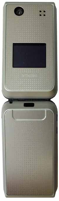
Click to zoom
Application Details
- Equipment Class
- PCE - PCS Licensed Transmitter held to ear
- Date of Grant
- Jan 06, 2005
- Application Purpose
- Original Equipment
- Date of Application
- Jan 06, 2005
- Equipment Note
- GSM850/1800/1900 Cellular Telephone
- Frequency Range
- 824.20000000 - 848.80000000
- Company
- Microsoft Corporation
- Country
- United States
Documents & Files
Document Text
Text extracted from the exhibit documents filed with the FCC. Open a document above to read the original.
Users Manual
Nokia 6170 User Guide 1Copyright © 2004 Nokia Nokia 6170 User Guide Note: Spanish translation of this user guide begins on page 101. 6170.ENESv1_BIL_9236732.book Page 1 Tuesday, November 16, 2004 1:30 PM 2Copyright © 2004 Nokia Quick guide Make a callEnter a phone number, and press Call. Answer a callPress Call, or open the fold. Answer call during call Select Options > Answer call. End a callPress End. Decline a callPress End. Mute a callSelect Mute during a call. RedialPress Call. Adjust call volumePress the Volume keys on the left side of the phone during a call. Use the in-call menuSelect Options during a call. Save a name and number Enter a number, select Save, enter a name, and select OK. Use 1-touch dialingPress and hold a key (2–8). You must assign a key to a number in Contacts. Look up a nameSelect Contacts > Find. Check voice mailPress and hold the 1 (contact your service provider for details). Write and send text messages Select Menu > Messages > Text messages > Create message. Enter the message, and select Send. Enter the number, and select OK. Send a picture message Select Menu > Messages > Text messages > Create message > Options > Insert picture. Scroll to the picture you want, and select View > Insert. Enter the text message, and select Send. Enter the number, and select OK. Read a new messageIf New Message appears, select Read, highlight the message, and select Read again. PressPress a key briefly and release it. Press and holdPress and hold a key for 2 to 3 seconds and release it. 6170.ENESv1_BIL_9236732.book Page 2 Tuesday, November 16, 2004 1:30 PM Nokia 6170 User Guide 3Copyright © 2004 Nokia DECLARATION OF CONFORMITY We, NOKIA CORPORATION declare under our sole responsibility that the products RM-47 and RM-48 are in conformity with the provisions of the following Council Directive: 1999/5/EC. A copy of the Declaration of Conformity can be found at http://www.nokia.com/phones/declaration_of_conformity/. LEGAL INFORMATION PART NO. 9235535 ISSUE NO. 1 Copyright © 2004 Nokia. All rights reserved. Nokia, Nokia Connecting People, Pop-Port, Xpress-on, Nokia Original Enhancements, Nokia 6170, and the Nokia Original Enhancements logos are trademarks or registered trademarks of Nokia Corporation. Other company and product names mentioned herein may be trademarks or trade names of their respective owners. Printed in Canada 10/2004 US Patent No 5818437 and other pending patents. T9 text input software Copyright © 1999-2004. Tegic Communications, Inc. All rights reserved. Includes RSA BSAFE cryptographic or security protocol software from RSA Security. Java is a trademark of Sun Microsystems, Inc. USE OF THIS PRODUCT IN ANY MANNER THAT COMPLIES WITH THE MPEG-4 VISUAL STANDARD IS PROHIBITED, EXCEPT FOR USE DIRECTLY RELATED TO (A) DATA OR INFORMATION (i) GENERATED BY AND OBTAINED WITHOUT CHARGE FROM A CONSUMER NOT THEREBY ENGAGED IN A BUSINESS ENTERPRISE, AND (ii) FOR PERSONAL USE ONLY; AND (B) OTHER USES SPECIFICALLY AND SEPARATELY LICENSED BY MPEG LA, L.L.C. The information contained in this user guide was written for the Nokia 6170 product. Nokia operates a policy of ongoing development. Nokia reserves the right to make changes to any of the products described in this document without prior notice. UNDER NO CIRCUMSTANCES SHALL NOKIA BE RESPONSIBLE FOR ANY LOSS OF DATA OR INCOME OR ANY SPECIAL, INCIDENTAL, AND CONSEQUENTIAL OR INDIRECT DAMAGES HOWSOEVER CAUSED. THE CONTENTS OF THIS DOCUMENT ARE PROVIDED "AS IS." EXCEPT AS REQUIRED BY APPLICABLE LAW, NO WARRANTIES OF ANY KIND, EITHER EXPRESS OR IMPLIED, INCLUDING, BUT NOT LIMITED TO, THE IMPLIED WARRANTIES OF MERCHANTABILITY AND FITNESS FOR A PARTICULAR PURPOSE, ARE MADE IN RELATION TO THE ACCURACY AND RELIABILITY OR CONTENTS OF THIS DOCUMENT. NOKIA RESERVES THE RIGHT TO REVISE THIS DOCUMENT OR WITHDRAW IT AT ANY TIME WITHOUT PRIOR NOTICE. EXPORT CONTROLS This device may contain commodities, technology or software subject to export laws and regulations from the US and other countries. Diversion contrary to law is prohibited. FCC/INDUSTRY CANADA NOTICE Your device may cause TV or radio interference (for example, when using a telephone in close proximity to receiving equipment). The FCC or Industry Canada can require you to stop using your telephone if such interference cannot be eliminated. If you require assistance, contact your local service facility. This device complies with part 15 of the FCC rules. Operation is subject to the condition that this device does not cause harmful interference. 6170.ENESv1_BIL_9236732.book Page 3 Tuesday, November 16, 2004 1:30 PM 4Copyright © 2004 Nokia Manufactured or sold under one or more following US Patents. Asterisk (*) indicates design patents pending. 486884655198855827082596637861120996266330 496919255263665835889597005961156176282436 500137255531255839101598713761187756285888 50459735557639584884599171661218466292668 510117555658215845219599185761224986295286 521283455703695857151599952361283226308084 523009155812445862178600585761285096310609 523363455971025870683601185361380916311054 524128456252745887266601457361409666314166 524158356403955889770601827761442436324412 526678256640045892475602616161446766347218 5 3111 5156640535898925602856761482096356759 531117956690695907823602912861514856359904 531728356776205914690603823861515076363259 533163856782245914796604376061636096370362 533536256920325915440604719661645476370390 535332856994065917868604979661672486377803 537893556994825920826605041561700736393121 538478257013925926138605543961785356430721 539022357295345926769606019361852956434133 53966575729541593023360699236188909*29/170210 54009495734683594665160727876195338*29/170229 54164355754976595633260815346199035*29/170245 54425215760568595662560849626201876*29/170246 54448165782646595663360887466219560 54463645794142596035460945876240076 54794765802465596038960979646240079 54870845805084596390161057846249584 54932555805301596637461085536259312 6170.ENESv1_BIL_9236732.book Page 4 …
Text truncated - open the document above for the full version.
Cover Letter(s)
NOKIA CORPORATION Nokia Mobile Phones Elektroniikkatie 10 FIN-90570 OULU FINLAND Tel. +358 7180 08000 Fax. +358 7180 47222 September 13, 2004 Federal Communications Commission, Authorization & Evaluation Division, 7435 Oakland Mills Road, Columbia, MD. 21046 Attention: Equipment Authorization Branch REQUEST FOR CONFIDENTIALITY Pursuant to Sections 0.457 (d) (l) (ii) and 0.459 of the Commission’s Rules, the Applicant hereby requests confidential treatment of some of the information accompanying this Application of FCC ID: LJPRM-48 and as outlined below: - Exhibit 4: Block Diagram - Exhibit 5: Schematic Diagrams - Exhibit 10: List of Active Devices and Tune-Up Procedure - Exhibit 12: Theory of Operation / Description of Circuitry These materials contain trade secrets and proprietary information not customarily released to the public and the public disclosure of these matters might be harmful to the Applicant and provide unjustified benefits to its competitors. The Applicant understands that pursuant to Rule 0.457 (d) (l) (ii) disclosure of this Application and all accompanying documentation will not be made before the date of the Grant for this Application. NOKIA CORPORATION Ismo Savikoski Product Program Manager Mobile Phones, Oulu
Cover Letter(s)
January 2, 2005 RE: FCC ID: LJPRM-48_ATCB002050 Attention: Kare Oksanen I have a few comments on this Application. Please note that further comments may arise in response to answers provided to the questions below. 1. Please provide the manual for this device. 2. FYI - Please note that the proper ANSI C63.4 version to reference in Part 15 testing is ANSI C63.4 2003. 3. FYI – Please be consistent in the report documentation. Part of the report states the measurements were made at 3 meters (section 4.2.1) and part says it was performed at 1.6m (section 4.27). While a distance correction factor has been provided, the report should still be consistent. 4. Please note that part 22 devices must report power in ERP not EIRP. Please provide power measurement data in ERP for the Part 22 portion. 5. Please note that it appears that the radiated emissions has been reported in EIRP. Please note that Part 22 spurious emissions is to be reported in ERP not EIRP. Please report radiated spurious emissions in ERP. 6. Please provide the required test setup photos for the Part 15B submittal. 7. For IC please provide the RSP100 form. Dennis Ward mailto:[email protected] The items indicated above must be submitted before processing can continue on the above referenced application. Failure to provide the requested information may result in application termination. Correspondence should be considered part of the permanent submission and may be viewed from the Internet after a Grant of Equipment Authorization is issued. Please do not respond to this correspondence using the email reply button. In order for your response to be processed expeditiously, you must submit your documents through the AmericanTCB.com website. Also, please note that partial responses increase processing time and should not be submitted. Any questions about the content of this correspondence should be directed to the sender.
Cover Letter(s)
RESPONSE 1 (1) Kare Oksanen 3 rd January 2005 1. Please provide the manual for this device. I will do that. And immediately after that, I will also press for the first time button “Notify that all files are uploaded to expedite the review process.” :-) 2. FYI - Please note that the proper ANSI C63.4 version to reference in Part 15 testing is ANSI C63.4 2003. I will notify the lab of this issue. 3. FYI – Please be consistent in the report documentation. Part of the report states the measurements were made at 3 meters (section 4.2.1) and part says it was performed at 1.6m (section 4.27). While a distance correction factor has been provided, the report should still be consistent. I agree that there is room for some improvement in wording. Measurements were made at 1.6m and them calculated by distance correctorion factor to 3m. I wil notify the lab of this. 4. Please note that part 22 devices must report power in ERP not EIRP. Please provide power measurement data in ERP for the Part 22 portion. Unfortunately I uploaded obsoleted version of test reports, which included also typos in power measurement data. Revised power output test reports for both part 22 and 24 have now been uploaded into your server. 5. Please note that it appears that the radiated emissions has been reported in EIRP. Please note that Part 22 spurious emissions is to be reported in ERP not EIRP. Please report radiated spurious emissions in ERP. Results are already reported correctly in ERP, as mentioned in section 7.5. However, there is mistake in formula in the same paragraph. Antenna gain is actually in dBd (gain over dipole), not in dBi as claimed in formula. 6. Please provide the required test setup photos for the Part 15B submittal. Please see answer #1. 7. For IC please provide the RSP100 form. Please see answer #1.
External Photos
3 Dec 2004 External Photographs FCC ID: LJPRM-48 Exhibit 3 IC: 661E-RM48 Applicant: Nokia Corporation Copyright © 2004 Nokia. All rights reserved. 3 Dec 2004 External Photographs FCC ID: LJPRM-48 Exhibit 3 IC: 661E-RM48 Applicant: Nokia Corporation Copyright © 2004 Nokia. All rights reserved. 3 Dec 2004 External Photographs FCC ID: LJPRM-48 Exhibit 3 IC: 661E-RM48 Applicant: Nokia Corporation Copyright © 2004 Nokia. All rights reserved.
ID Label/Location Info
Label Location Exhibit 1 Applicant: Nokia Corporation FCC ID: LJPRM-4 IC: 661E-RM4 8 8 Copyright2004 Nokia. All Rights Reserved. 17 Dec 2004 168 XXXXXX / xx / yyyyyy / 0 Type: RM-48 Nokia Corporation Model: 6170b CODE: XXXXXXX FCC ID: LJPRM-48 IC: 661E-RM48 Label Exhibit 1 Applicant: Nokia Corporation FCC ID: LJPRM-4 IC: 661E-RM4 8 8 Copyright2004 Nokia. All Rights Reserved. 17 Dec 2004 168 XXXXXX / xx / yyyyyy / 0 Type: RM-48 Nokia Corporation Model: 6170b CODE: XXXXXXX FCC ID: LJPRM-48 IC: 661E-RM48
Internal Photos
3 Dec 2004 Internal Photographs FCC ID: LJPRM-48 Exhibit 9 IC: 661E-RM48 Applicant: Nokia Corporation Copyright © 2004 Nokia. All rights reserved. 3 Dec 2004 Internal Photographs FCC ID: LJPRM-48 Exhibit 9 IC: 661E-RM48 Applicant: Nokia Corporation Copyright © 2004 Nokia. All rights reserved. 3 Dec 2004 Internal Photographs FCC ID: LJPRM-48 Exhibit 9 IC: 661E-RM48 Applicant: Nokia Corporation Copyright © 2004 Nokia. All rights reserved.
RF Exposure Info
Oulu ____________________________________________________________________________ SAR Report Oulu_SAR_0451_02 Applicant: Nokia Corporation Type: RM-48 Copyright © 2004 TCC Oulu 2/45 CONTENTS 1. SUMMARY OF SAR TEST REPORT 3 1.1 TEST DETAILS 3 1.2 MAXIMUM RESULTS 3 1.2.1 Head Configuration 3 1.2.2 Body Worn Configuration 3 1.2.3 Maximum Drift 3 1.2.4 Measurement Uncertainty 4 2. DESCRIPTION OF THE DEVICE UNDER TEST 4 2.1 PICTURE OF THE DEVICE 5 2.2 DESCRIPTION OF THE ANTENNA 5 3. TEST CONDITIONS 5 3.1 TEMPERATURE AND HUMIDITY 5 3.2 TEST SIGNAL, FREQUENCIES, AND OUTPUT POWER 5 4. DESCRIPTION OF THE TEST EQUIPMENT 6 4.1 MEASUREMENT SYSTEM AND COMPONENTS 6 4.1.1 Isotropic E-field Probe ET3DV6 7 4.2 PHANTOMS 8 4.3 SIMULATING LIQUIDS 8 4.3.1 Liquid Recipes 8 4.3.2 Verification of the System 9 4.3.3 Tissue Simulants used in the Measurements 10 5. DESCRIPTION OF THE TEST PROCEDURE 11 5.1 DEVICE HOLDER 11 5.2 TEST POSITIONS 11 5.2.1 Against Phantom Head 11 5.2.2 Body Worn Configuration 12 5.3 SCAN PROCEDURES 12 5.4 SAR AVERAGING METHODS 13 6. MEASUREMENT UNCERTAINTY 14 7. RESULTS 15 APPENDIX A: VALIDATION SCANS 17 APPENDIX B: MEASUREMENT SCANS 23 APPENDIX C: RELEVANT PAGES FROM PROBE CALIBRATION REPORT(S) 44 APPENDIX D: RELEVANT PAGES FROM DIPOLE VALIDATION KIT REPORT(S) 45 Oulu ____________________________________________________________________________ SAR Report Oulu_SAR_0451_02 Applicant: Nokia Corporation Type: RM-48 Copyright © 2004 TCC Oulu 3/45 1. SUMMARY OF SAR TEST REPORT 1.1 Test Details Period of test 2004-12-07 to 2004-12-09 SN, HW and SW numbers of tested device SN: 004400/49/164873/7, HW: 10581703, SW: 13.22 Batteries used in testing BL-4C, DUT#'s:0046, 0047, 0048 Headsets used in testing HS-3, DUT#:0044 Other accessories used in testing State of sample Prototype Unit Notes 1.2 Maximum Results The maximum measured SAR values for Head configuration and Body Worn configuration are given in section 1.2.1 and 1.2.2 respectively. The device conforms to the requirements of the standard(s) when the maximum measured SAR value is less than or equal to the limit. 1.2.1 Head Configuration Mode Ch / f (MHz) ERP/EIRP Position SAR limit (1g avg) Measured SAR value (1g avg) Result 2-slot GPRS 850 190 / 836.6 30.14 dBm Left Cheek 1.6 W/kg 0.48 W/kg PASSED GSM 1900 810 / 1909.8 29.7 dBm Right Cheek 1.6 W/kg 1.12 W/kg PASSED 1.2.2 Body Worn Configuration Mode Ch / f (MHz) ERP/EIRP Separation distance SAR limit (1g avg) Measured SAR value (1g avg) Result 2-slot GPRS 850 190 / 836.6 30.14 dBm 1.5 cm 1.6 W/kg 0.32 W/kg PASSED 2-slot GPRS 1900 810 / 1909.8 30.09 dBm 1.5 cm 1.6 W/kg 1.09 W/kg PASSED 1.2.3 Maximum Drift Maximum drift during measurements -0.3 dB Oulu ____________________________________________________________________________ SAR Report Oulu_SAR_0451_02 Applicant: Nokia Corporation Type: RM-48 Copyright © 2004 TCC Oulu 4/45 1.2.4 Measurement Uncertainty Extended Uncertainty (k=2) 95% ± 29.8 % 2. DESCRIPTION OF THE DEVICE UNDER TEST Device category portable Exposure environment general population/uncontrolled Modes and Bands of Operation GSM 850 GSM 1900 GPRS E-GPRS Modulation Mode GMSK GMSK GMSK 8PSK Duty Cycle 1/8 1/8 1/8 or 2/8 1/8 or 2/8 Transmitter Frequency Range (MHz) 824.2 – 848.8 1850.2 - 1909.8 824.2-848.8 or 1850.2-1909.8 824.2-848.8 or 1850.2-1909.8 Outside of USA and Canada, the transmitter is capable of operating also in GSM 1800, which is not part of this filing. This device has Push-to-Talk/Voice-over-IP capability for use at the ear. Therefore, SAR for 2-slot GPRS mode was also evaluated against the head profile of the phantom. Oulu ____________________________________________________________________________ SAR Report Oulu_SAR_0451_02 Applicant: Nokia Corporation Type: RM-48 Copyright © 2004 TCC Oulu 5/45 2.1 Picture of the Device 2.2 Description of the Antenna The device has an internal patch antenna. 3. TEST CONDITIONS 3.1 Temperature and Humidity Period of measurement: 2004-12-07 to 2004-12-09 Ambient temperature (°C): 22.0 to 24.3 Ambient humidity (RH %): 20 to 39 3.2 Test Signal, Frequencies, and Output Power The device was put into operation by using a call tester. Communication between the device and the call tester was established by air link. The device output power was set to maximum power level for all tests; a fully charged battery was used for every test sequence. In all operating bands the measurements were performed on lowest, middle and highest channels. Oulu ____________________________________________________________________________ SAR Report Oulu_SAR_0451_02 Applicant: Nokia Corporation Type: RM-48 Copyright © 2004 TCC Oulu 6/45 The power output was measured by a separate test laboratory on the same unit as used for SAR testing. 4. DESCRIPTION OF THE TEST EQUIPMENT 4.1 Measurement System and Components The measurements were performed using an automated near-field scanning system, DASY 4 software version 4.4, manufactured by Schmid & Partner Engineering AG (SPEAG) in Switzerland. The SAR extrapolation algorithm used in all measurements on the device was the ‘worst-case extrapolation’ algorithm. The following table lists calibration dates of SPEAG components: Test Equipment Serial Number Calibration interval Calibration expiry Dasy4 DAE3 555 12 months 02/05 E-field Probe ET3DV6 1765 12 months 02/05 Dipole Validation kit, D835V2 480 24 months 04/05 Dipole Validation Kit, D1900V2 5d030 24 months 04/05 Additional test equipment used in testing: Oulu ____________________________________________________________________________ SAR Report Oulu_SAR_0451_02 Applicant: Nokia Corporation Type: RM-48 Copyright © 2004 TCC Oulu 7/45 Test Equipment Model Serial Number Calibration interval Calibration expiry Signal Generator HP 8657B 3630U08114 12 months 06/06 RF Amplifier AR 5S1G4 306024 - - Power Reflection Meter R&S NRT 101143 12 months 04/05 Directional Power Sensor R&S NRT-Z43 100239 12 months 04/05 Network Analyzer HP 8753D 3410A08934 12 months 06/05 Dielectric Pro…
Text truncated - open the document above for the full version.
Test Report
Fax. +358 (0) 7180 58300FCC Compliance Test Report / Template Version 1.0 Copyright © TCC Oulu 2 (8) TCC Oulu P.O. Box 300 Yrttipellontie 6 FIN-90230 OULU, FINLAND Tel. +358 (0) 7180 08000 CONTENTS 1. Summary of test results.........................................................................................................3 2. EUT Information.......................................................................................................................3 2.1. EUT description........................................................................................................................3 3. EUT Test Setup........................................................................................................................3 4. Applicable Standards.............................................................................................................4 5. Radiated RF output power....................................................................................................4 5.1. Test setup................................................................................................................................4 5.2. Test method.............................................................................................................................4 5.3. EUT operation mode................................................................................................................6 5.4. Limit..........................................................................................................................................6 5.5. Results.....................................................................................................................................6 6. Test equipment........................................................................................................................8 6.1. Conducted measurements......................................................................................................8 6.2. Radiated measurements.........................................................................................................8 Fax. +358 (0) 7180 58300FCC Compliance Test Report / Template Version 1.0 Copyright © TCC Oulu 3 (8) TCC Oulu P.O. Box 300 Yrttipellontie 6 FIN-90230 OULU, FINLAND Tel. +358 (0) 7180 08000 1. Summary of test results Section in CFR 47 Section in RSS-132 Result §2.1046 (a), 22.913 (a) 6.4 Conducted RF output power - §22.913 (a) 6.4 Radiated RF output power PASS §2.1049 (h) 4.2 99% occupied bandwidth - §22.917 (e) 4.5 Bandedge compliance - §22.917 (e), §2.1051 4.5 Spurious emissions at antenna terminals - §22.917 (e), §2.1053 4.5 Spurious radiated emission - §2.1055 (a)(1)(b) 6.3 Frequency stability, temperature variation - §2.1055 (d)(1)(2) 6.3 Frequency stability, voltage variation - PASS Pass FAIL Fail X Measured, but there is no applicable performance criteria NA Not Applicable - Not Measured 2. EUT Information Product Type SN HW MV SW DUT Phone RM-48 004400491648737 1058 - 1322 30266 Battery BL-4C - - - - 30277 AC-Charger ACP-12 047982 1.3 - - 0100 2.1. EUT description The EUT is a dual band ( 850MHz/1800MHz/1900MHz) GSM mobile phone The EUT was not modified during the tests. 3. EUT Test Setup For each test the EUT was excercised to find the worst case of operation modes and device configuration. The test setup photograph are in Appendix A Fax. +358 (0) 7180 58300FCC Compliance Test Report / Template Version 1.0 Copyright © TCC Oulu 4 (8) TCC Oulu P.O. Box 300 Yrttipellontie 6 FIN-90230 OULU, FINLAND Tel. +358 (0) 7180 08000 4. Applicable Standards The tests were performed in guidance of CFR 47 part 22, part 2, ANSI/TIA/EIA-603-A and RSS- 132. Deviations, modifications or clarifications (if any) to above mentioned documents are written in each section under "Test method" for each test case. 5. Radiated RF output power EUT RM-48 30266 Accessories BL-4C 30277, ACP-12 0100 Temp, Humidity, Air Pressure 20 ºC 47 RH% 990 mbar Date of measurement 30.12.2004 FCC rule part §22.913 (a) RSS-132 section 6.4 Measured by Juho Tuohino Result PASSED 5.1. Test setup The EUT was set on a non-conductive turntable in a semi anechoic chamber. In the corner of the chamber there was a communication antenna, which was connected to the BS simulator located outside the chamber. The radiated power from the EUT was measured with an antenna fixed to a antenna tower. The tower and turn table were remotely controlled to turn the EUT and change the antenna polarization. The measured signal was routed from the measuring antenna to the spectrum analyzer. The BS simulator was used to set the TX channel and power level and modulate the TX signal with different bit patterns. 5.2. Test method a) The maximum power level was searched by moving the turn table and measuring antenna and manipulating the EUT. This level (P EUT ) was recorded. EUT Spectrum analyzer BS simulator Tower / table controller Fax. +358 (0) 7180 58300FCC Compliance Test Report / Template Version 1.0 Copyright © TCC Oulu 5 (8) TCC Oulu P.O. Box 300 Yrttipellontie 6 FIN-90230 OULU, FINLAND Tel. +358 (0) 7180 08000 b) The EUT was replaced with a substituting antenna. c) The substituting antenna was fed with the power (P Subst_TX ) giving a convenient reading on the spectrum analyzer. That reading (P Subst_RX ) on spectrum analyzer was recorded. Fax. +358 (0) 7180 58300FCC Compliance Test Report / Template Version 1.0 Copyright © TCC Oulu 6 (8) TCC Oulu P.O. Box 300 Yrttipellontie 6 FIN-90230 OULU, FINLAND Tel. +358 (0) 7180 08000 5.3. EUT operation mode GSM EGPRS EUT operation mode TX on, 1 time slot transmission, GMSK modulation TX on, 2 time slot transmission, 8PSK modulation EUT channel 128, 190, 251 128, 190, 251 EUT TX power level 5 (+33dBm) 5 (+33dBm) 5.4. Limit ERP [W] FCC = 7 IC = 6.3 5.5. Results The formula below was used to calculate the ERP. where the variables are as follows: P EUT [dBm] Measured power level (from step a in 5.2) from the EUT P Sub…
Text truncated - open the document above for the full version.
Test Report
FCC Compliance Test Report / Template Version 1.0 Test Report No.: Cph_FCC_0451_06.doc TCC CO Test report – Server: \\satcc01nmp\Projects\ Copyright © TCC Copenhagen 2 (17) TCC Copenhagen Frederikskaj 1790 COPENHAGEN V DENMARK Tel. +45 33 292929 Fax. +45 33 292934 CONTENTS 1. Summary of test results.............................................................................................4 2. EUT Information..........................................................................................................4 2.1. EUT description......................................................................................................................4 3. EUT Test Setup...........................................................................................................4 4. Applicable Standards.................................................................................................5 5. 99% occupied bandwidth...........................................................................................6 5.1. Test setup..............................................................................................................................6 5.2. EUT operation mode..............................................................................................................6 5.3. Results...................................................................................................................................6 5.4. Screen shot............................................................................................................................7 6. Bandedge compliance................................................................................................8 6.1. Test setup..............................................................................................................................8 6.2. EUT operation mode..............................................................................................................8 6.3. Limit........................................................................................................................................8 6.4. Results...................................................................................................................................8 6.5. Screen shots..........................................................................................................................9 7. Spurious radiated emission.....................................................................................11 7.1. Test setup............................................................................................................................11 7.2. Test method.........................................................................................................................11 7.3. EUT operation mode............................................................................................................12 7.4. Limit......................................................................................................................................12 7.5. Results.................................................................................................................................12 8. Frequency stability, temperature variation............................................................13 8.1. Test setup............................................................................................................................13 8.2. EUT operation mode............................................................................................................13 8.3. Limit......................................................................................................................................13 8.4. Test method.........................................................................................................................13 8.5. Results..................................................................................................................................14 9. Frequency stability, voltage variation.....................................................................15 9.1. Test setup............................................................................................................................15 9.2. EUT operation mode............................................................................................................15 9.3. Limit......................................................................................................................................15 9.4. Test method.........................................................................................................................15 9.5. Results.................................................................................................................................15 FCC Compliance Test Report / Template Version 1.0 Test Report No.: Cph_FCC_0451_06.doc TCC CO Test report – Server: \\satcc01nmp\Projects\ Copyright © TCC Copenhagen 3 (17) TCC Copenhagen Frederikskaj 1790 COPENHAGEN V DENMARK Tel. +45 33 292929 Fax. +45 33 292934 10. Test equipment...................................................................................................... 16 10.1. Conducted measurements ...............................................................................................16 10.2. Radiated measurements ..................................................................................................16 FCC Compliance Test Report / Template Version 1.0 Test Report No.: Cph_FCC_0451_06.doc TCC CO Test report –…
Text truncated - open the document above for the full version.
Contact Information
Applicant
Hasnain Syed(Director, EMC, SI and RF Compliance)
Technical Contact
Nokia CorporationKare Oksanen
[email protected]011 358 7180 08000
Elektroniikkatie 10 · OULU · Finland
Technical Specifications
| # | Rule Parts | Frequency Range | Power Output | Emission | Tolerance |
|---|---|---|---|---|---|
| 4 | 22H | 824.2 MHz - 848.8 MHz | 597.00 mW | 300KG7W | 0.1 ppm |
Other Applications from Microsoft Corporation
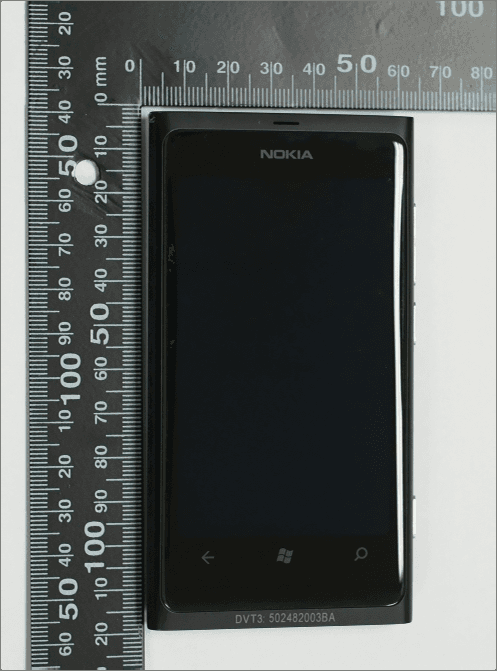
LJPA
Dec 20, 2011GSM/WCDMA cellular phone w/BT and WLAN
Equipment Class
DTS - Digital Transmission System
LJPRM-801
Oct 08, 2011GSM/WCDMA cellular phone w/BT and WLAN
Equipment Class
JBP - Part 15 Class B Computing Device Peripheral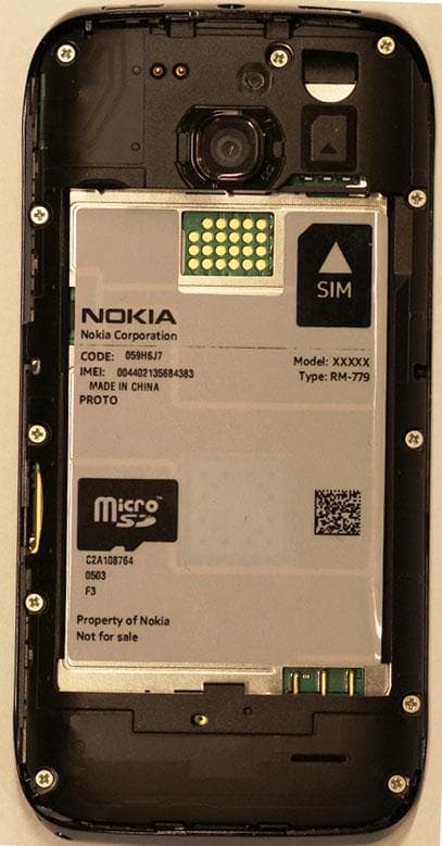
LJPRM-779
Sep 29, 2011GSM/WCDMA cellular phone w/BT, WLAN and NFC
Equipment Class
DTS - Digital Transmission System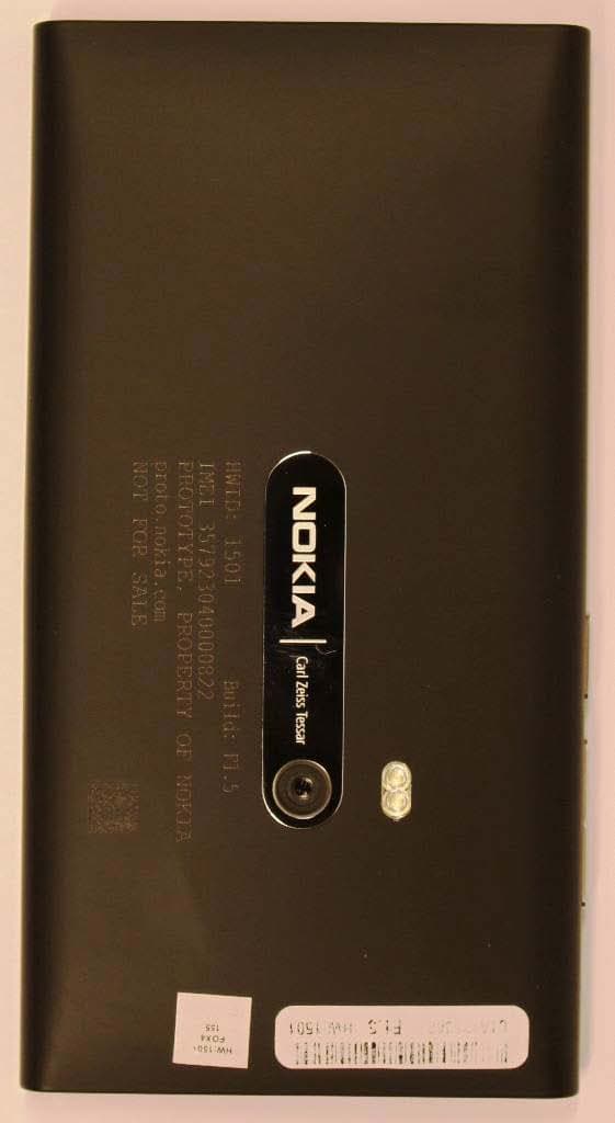
LJPK
Jul 20, 2011GSM/WCDMA cellular telephone with BT, WLAN, and NFC
Equipment Class
DTS - Digital Transmission System
LJPRM-701
Jul 20, 2011GSM/WCDMA cellular phone w/BT, WLAN, FMTx and NFC
Equipment Class
DXX - Part 15 Low Power Communication Device Transmitter