LJPRX-9GSM/EGPRS 850/1900 M2M Module
Microsoft Corporation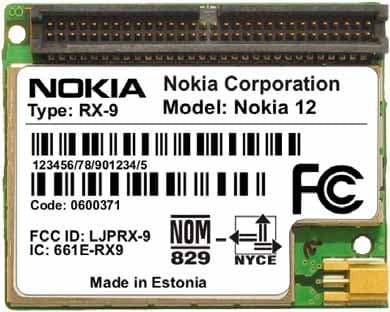
Click to zoom
Application Details
- Equipment Class
- PCB - PCS Licensed Transmitter
- Date of Grant
- Feb 01, 2004
- Application Purpose
- Original Equipment
- Date of Application
- Feb 01, 2004
- Equipment Note
- GSM/EGPRS 850/1900 M2M Module
- Frequency Range
- 824.20000000 - 848.80000000
- Company
- Microsoft Corporation
- Country
- United States
Documents & Files
Document Text
Text extracted from the exhibit documents filed with the FCC. Open a document above to read the original.
Users Manual
C o pyrig h t ©2 00 3- 2 004 Nokia . A ll rig h ts re se rve d | D a te : 2 8 . 01. 04, ve r. 1. 2 INTEGRATOR’S MANUAL FOR NOKIA 12 RX-2, RX-9 Copyright © Nokia 2003-2004. All rights reserved. Contents 1. INTRODUCTION...................................................................................................................................................1 2. MECHANICAL INTEGRATION.............................................................................................................................1 3. ELECTRICAL INTEGRATION................................................................................................................................3 3.1 M2M SYSTEM CONNECTOR........................................................................................................................3 3.1.1 ELECTRICAL CHARACTERISTICS............................................................................................................4 3.1.2 CONNECTOR PIN-OUT............................................................................................................................5 3.2 GROUNDING..............................................................................................................................................12 3.3 POWER SUPPLY........................................................................................................................................12 3.4 SERIAL COMMUNICATION.......................................................................................................................13 3.4.1 AT COMMAND MODE...........................................................................................................................13 3.4.2 M2M SYSTEM MODE............................................................................................................................13 3.5 SIM INTERFACE.........................................................................................................................................13 3.6 AUDIO INTERFACE...................................................................................................................................14 3.6.1 ANALOG AUDIO....................................................................................................................................14 3.6.2 ANALOG AUDIO EXAMPLE..................................................................................................................16 3.6.3 ACOUSTIC ECHO...................................................................................................................................18 3.7 DIGITAL AUDIO.........................................................................................................................................18 3.7.1 SIGN-EXTENDED LINEAR CODE......................................................................................................... 19 4. RF AND ANTENNA INTEGRATION.................................................................................................................20 4.1 ANTENNA INSTALLATION......................................................................................................................20 5. TEST BOARD FOR THE NOKIA 12..................................................................................................................21 5.1 POWERING................................................................................................................................................21 5.2 SIM CARD READER...................................................................................................................................21 5.3 RS-232 CONVERTERS..............................................................................................................................22 5.4 AUDIO.........................................................................................................................................................22 6. CERTIFICATIONS...............................................................................................................................................24 6.1.1 RX-2:......................................................................................................................................................25 6.1.2 RX-9.......................................................................................................................................................25 6.2 TECHNICAL REQUIREMENTS...................................................................................................................25 Copyright © Nokia 2003-2004. All rights reserved. 6.2.1 SIM TESTING........................................................................................................................................25 6.2.2 POWER SUPPLY...................................................................................................................................25 6.2.3 EMC/ESD AND SAFETY........................................................................................................................25 6.2.4 RF TESTING...........................................................................................................................................26 6.2.5 RF EXPOSURE.......................................................................................................................................26 6.2.6 OTHER TYPE APPROVAL ISSUES....................................................................................................... 26 Legal Notice Copyright © 2003-2004 Nokia. All rights reserved. Reproduction, transfer, distribution or storage of part or all of the contents in this document in any form without the prior written permission of Nokia is prohibited. Nokia and Nokia Connecting People are registered trademarks of Nokia Corporation. Other product and company names mentioned herein may be trademarks or tradenames of their respective owners. N…
Text truncated - open the document above for the full version.
Cover Letter(s)
NOKIA CORPORATION Nokia Mobile Phones Elektroniikkatie 10 FIN-90570 OULU FINLAND Tel. +358 7180 08000 Fax. +358 7180 47222 December 1, 2003 Federal Communications Commission, Authorization & Evaluation Division, 7435 Oakland Mills Road, Columbia, MD. 21046 Attention: Equipment Authorization Branch REQUEST FOR CONFIDENTIALITY Pursuant to Sections 0.457 (d) (l) (ii) and 0.459 of the Commission’s Rules, the Applicant hereby requests confidential treatment of some of the information accompanying this Application of FCC ID: LJPRX-9 and as outlined below: - Exhibit 4: Block Diagram - Exhibit 5: Schematic Diagrams - Exhibit 10: List of Active Devices and Tune-Up Procedure - Exhibit 12: Theory of Operation / Description of Circuitry These materials contain trade secrets and proprietary information not customarily released to the public and the public disclosure of these matters might be harmful to the Applicant and provide unjustified benefits to its competitors. The Applicant understands that pursuant to Rule 0.457 (d) (l) (ii) disclosure of this Application and all accompanying documentation will not be made before the date of the Grant for this Application. NOKIA CORPORATION Jyrki Hietaniemi Product Program Manager Nokia Mobile Phones, ME Oulu
Cover Letter(s)
American Telecommunications Certification Body Inc. 6731 Whittier Ave, McLean, VA 22101 January 30, 2004 RE: FCC ID: LJPRX-9_ATCB001078 Attention: Kare Oksanen I have a few comments on this Application. 1. FYI - Please note that MPE for the 824 MHz band has been provided, but MPE for the 1900 PCS band does not appear to have been provided. While the calculated safe distance would obviously be better than the 800MHz calculations due to power etc, the MPE for all bands should be considered in the MPE report. 2. Please note that you have stated on the 731 that this is a device that is held to the ear (PCE). However, the device is a mobile module with an antenna that is to be kept at least 20cm from the body at all times. As a mobile module, this would be classified as a Licensed Base Station (PCB equipment code). Also please note that the power listed on the grant for equipment code PCB would be the conducted power at the antenna terminal. The ERP and EIRP could then be listed in the grant notes. Please correct the 731 to reflect the proper equipment code and power listings. 3. Please note that the report states the use of ANSI C63.4 as a “Standard Test Condition”. Please note that ANSI C63.4 is primarily for use with unlicensed Part 15 devices. Except for the mention of ANSI C63.4 section 5.4 for OATS requirements during ERP/EIRP measurements in TIA603, ANSI C63.4 is not an appropriate reference for licensed PCS devices. Please explain why ANSI C63.4 was used. 4. Please note that the MPE report states that a “Customer Supplied” antenna can have a gain of 6 dBi. Please note that the manual (page 31) states that the antenna gain for other than that supplied in the “sales package” is not to exceed 3dBi. Please explain and reconcile the conflicting statements. 5. The manual does not state that the antenna provided in the “sales package” is 6dBi. Also, the report does not clearly identify the gain of the EUT antenna used during ERP and EIRP measurements. Please verify that the ERP and EIRP measurements were performed using an EUT antenna with the maximum antenna gain allowed for the device (i.e. 6dBi). Dennis Ward mailto:[email protected] The items indicated above must be submitted before processing can continue on the above referenced application. Failure to provide the requested information may result in application termination. Correspondence should be considered part of the permanent submission and may be viewed from the Internet after a Grant of Equipment Authorization is issued. Please do not respond to this correspondence using the email reply button. In order for your response to be processed expeditiously, you must submit your documents through the AmericanTCB.com website. Also, please note that partial responses increase processing time and should not be submitted. Any questions about the content of this correspondence should be directed to the sender.
Cover Letter(s)
RESPONSE 1 (1) TCC Oulu Kare Oksanen 02/02/2004 1. FYI - Please note that MPE for the 824 MHz band has been provided, but MPE for the 1900 PCS band does not appear to have been provided. While the calculated safe distance would obviously be better than the 800MHz calculations due to power etc, the MPE for all bands should be considered in the MPE report. I have updated MPE calculation to address also PCS band. This is related also to question #4. 2. Please note that you have stated on the 731 that this is a device that is held to the ear (PCE). However, the device is a mobile module with an antenna that is to be kept at least 20cm from the body at all times. As a mobile module, this would be classified as a Licensed Base Station (PCB equipment code). Also please note that the power listed on the grant for equipment code PCB would be the conducted power at the antenna terminal. The ERP and EIRP could then be listed in the grant notes. Please correct the 731 to reflect the proper equipment code and power listings. You are absolutely correct, and I apologize for any inconvenience I have caused. I have now updated form 731. 3. Please note that the report states the use of ANSI C63.4 as a “Standard Test Condition”. Please note that ANSI C63.4 is primarily for use with unlicensed Part 15 devices. Except for the mention of ANSI C63.4 section 5.4 for OATS requirements during ERP/EIRP measurements in TIA603, ANSI C63.4 is not an appropriate reference for licensed PCS devices. Please explain why ANSI C63.4 was used. Test reports lists ANSI C63.4 used as standard test condition only for ambient temperature. While this temperature range is a little bit wider than the one given in TIA-603-B, it is more appropriate for OATS. Tested device compensates changes in temperature. 4. Please note that the MPE report states that a “Customer Supplied” antenna can have a gain of 6 dBi. Please note that the manual (page 31) states that the antenna gain for other than that supplied in the “sales package” is not to exceed 3dBi. Please explain and reconcile the conflicting statements. As stated in answer #1, MPE calculation is now revised to 3 dBi. Earlier version was obsolete as plans for antenna with 6 dBi gain were postponed, but unfortunately it still ended up into our application. Please disregard old version of this document. 5. The manual does not state that the antenna provided in the “sales package” is 6dBi. Also, the report does not clearly identify the gain of the EUT antenna used during ERP and EIRP measurements. Please verify that the ERP and EIRP measurements were performed using an EUT antenna with the maximum antenna gain allowed for the device (i.e. 6dBi). There are several different kinds of sales packages, of which some include antenna while others do not. This antenna is identified in section 4 of manual, and it has gain of 0dBd (2.14dBi) in 850 and 1900 bands. While this gain is typical for this kind of antennas, for notification text, this number was rounded up to next integer in dBi for users who want to have antenna from different manufacturer. During ERP/EIRP measurements, effect of connection cable was compensated by cable loss factor, while in normal usage expected actual gain is lower due to cable loss. Sincerely, Kare Oksanen
External Photos
01 Dec 2003 External Photographs FCC ID: LJPRX-9 IC: 661E-RX9 Applicant: Nokia Corporation Copyright © 2003 Nokia. All rights reserved.
ID Label/Location Info
Code: 0600371 Model: Nokia 12 Type: RX-9 123456/78/901234/5 Made in Estonia Nokia Corporation FCC ID: LJPRX-9 IC: 661E-RX9 Code: 0600371 Model: Nokia 12 Type: RX-9 123456/78/901234/5 Made in Estonia Nokia Corporation FCC ID: LJPRX-9 IC: 661E-RX9 Exhibit 1: Type Label Applicant: Nokia Corporation FCC ID: LJPRX-9 IC: 661E-RX9 Copyright © 2004 Nokia. All rights reserved. 15 Jan 2004 NOKIA CORPORATION Nokia Mobile Phones Elektroniikkatie 10 FIN-90570 OULU FINLAND Tel. +358 7180 08000 Fax. +358 7180 47222 December 1, 2003 Federal Communications Commission, Authorization & Evaluation Division, 7435 Oakland Mills Road, Columbia, MD. 21046 Attention: Equipment Authorization Branch COMPLIANCE STATEMENT OF LJPRX-9 The compliance statement can be seen in User Guide of LJPRX-9 because the size of the handportable LJPRX-9 and its identification label are so small that the compliance statement cannot be printed visible enough. NOKIA CORPORATION Jyrki Hietaniemi Product Program Manager Nokia Mobile Phones, ME Oulu
Internal Photos
01 Dec 2003 Internal Photographs FCC ID: LJPRX-9 IC: 661E-RX9 Applicant: Nokia Corporation Copyright © 2003 Nokia. All rights reserved.
RF Exposure Info
ENVIRONMENTAL EVALUATION 1 (5) 2.2.2004 Environmental Evaluation of RF Exposure for the Embedded GSM Terminal RX-9 ENVIRONMENTAL EVALUATION 2 (5) 2.2.2004 TABLE OF CONTENTS 1. Introduction .................................................................................................................................... 3 1.1 Purpose of the Report ............................................................................................................. 3 1.2 Description of the RX-9 Terminal ............................................................................................ 3 2. Classification of Device / Applicability of Rules..............................................................................3 2.1 Mobile terminal ........................................................................................................................ 3 2.2 Excludability from routine environmental evaluation ............................................................... 4 2.3 Applicable limits for exposure to radio frequency exposure .................................................... 4 3. RF Exposure Analysis.................................................................................................................... 5 3.1 Power Output........................................................................................................................... 5 3.2 Class 4 Operation – GSM 850................................................................................................. 5 3.3 Class 1 Operation – GSM 1900............................................................................................... 5 4. Conclusions.................................................................................................................................... 5 ENVIRONMENTAL EVALUATION 3 (5) 2.2.2004 1. INTRODUCTION 1.1 Purpose of the Report This technical report is a detailed environmental evaluation of the radio frequency exposure expected from use of the RX-9 transmitter. The following analysis demonstrates that the RX-9 terminal is in compliance with the requirements for maximum permissible exposure (MPE) to radiofrequency exposure as defined in the FCC Rules, 47 CFR 2.1091, as amended. 1.2 Description of the RX-9 Terminal The RX-9 Transceiver has been designed as M2M terminal. RX-9 terminal uses only external antenna, which is attached into terminal. All calculations related to MPE are made using antenna gain guidelines provided in customer documentation such as the RX-9 Installation Manual. The module has two functional modes of operation: (1) GSM 850 mode - Class 4 terminal (2) GSM 1900 mode - Class 1 terminal In the GSM 850 band (824 to 849 MHz), the transmitter section delivers up to 2 Watts bursted output power in GPRS mode of operation (max two TX slots per frame). In GSM 1900 band, the transmitter section delivers up to 1 Watt bursted output power in GPRS mode of operation (max two TX slots per frame). This device includes also EGPRS mode, but its output is considerably lower than in GPRS mode. This transceiver is designed primarily for applications where the unit is located within the application 2. CLASSIFICATION OF DEVICE / APPLICABILITY OF RULES 2.1 Mobile terminal The RX-9 terminal is properly defined as a mobile terminal per 47 CFR 2.1091 (b), which states that “mobile devices are defined as transmitters designed to be used in other than fixed locations and to generally be used in such a way that a separation distance of at least 20 centimeters is normally maintained between radiating antennas and the body of the user or nearby persons.” For most applications of the RX-9, there is typically a separation distance of greater than 20 centimeters. The discussion below will demonstrate that the maximum likely exposures in these applications are significantly below the maximums permitted. However, whenever possible, the transmitter should be installed in such a manner as to make it unlikely that a human body can be maintained in close proximity (i.e. less than 20 centimeters) to the radiating antenna. A statement to this effect is included in the manual supplied to the customers using this device (RX-9 User Guide). This statement should make it clear that Nokia does not mean to imply that proximities of less than 20 centimeters are unsafe. Rather, maintaining a separation of at least 20 centimeters simply ensures that the analysis below is valid and that the margins with respect to the maximum permissible exposures that are demonstrated below are maintained. ENVIRONMENTAL EVALUATION 4 (5) 2.2.2004 2.2 Excludability from routine environmental evaluation 47 CFR 2.1091(c) states that “mobile devices that operate in the Cellular Radiotelephone Service...are subject to routine environmental evaluation for RF exposure prior to equipment authorization or use if... their effective radiated power (ERP) is 1.5 Watts or more.” For Class 4 operation, the RX-9 transceiver is rated at 2 Watts of output power in GSM 850 mode. The User’s Manual supplied to customers specifies the use of an antenna with maximum system gain of 3 dBi. The following sections analyze the maximum RF radiation exposures from a RX-9 transmitter under maximum and typical conditions. This analysis will clearly demonstrate compliance with the amended FCC rules. 2.3 Applicable limits for exposure to radio frequency exposure The following paragraphs analyze the maximum RF radiation exposures from a RX-9 transmitter under extreme and typical conditions. This analysis will clearly demonstrate compliance with the amended FCC rules. The table below is excerpted from Table 1B of 47 CFR 1.1310 titled Limits for Maximum Permissible Exposure (MPE), Limits for General Population/Uncontrolled Exposure: Frequency Range (MHz) Power Density (mW/cm 2 ) Averaging Time (minutes) 300 - 1500 f/1500 30 1500 – 100,000 1.0 30 where f = frequency in MHz. The lowest frequency of operation in the cellular band is 824 MHz, so the MPE …
Text truncated - open the document above for the full version.
Test Report
FCC ID: LJPRX-9 Date: January 26, 2004 Applicant: Nokia Corporation Elektroniikkatie 10 Fin-90570 Oulu, Finland Attention of: Kare Oksanen, R&D Type Approvals [email protected] 011 358 7180 08000; FAX: 011 358 7180 47222 Equipment: RX-9 FCC ID: LJPRX-9 P.O. Number: K.O. 12/11/2003 FCC Rules: 22H, 22.901(d), 24E, Confidentiality Gentlemen: Enclosed please find your copy of the Engineering Test Report for which you are subject to the restrictions as listed on the attached summary. As you know, the FCC, after a TCB issues a Grant, still has 30 days to review a submission and request added information. It is your decision whether or not to market the equipment subject to a possible recall before the end of the 30 days. The invoice for services has already been sent to you to direct to your Accounts Payable Department. Please advise if you need another copy. Should you need any clarification, just fax or phone. Thank you again for this order - it has been a pleasure to be of service. Sincerely yours, Morton Flom, P. Eng. enclosure(s) MF/cva MFA p03c0005, d03c0034 FCC ID: LJPRX-9 Memo Date: December 19, 2003 Applicant: Nokia Corporation Elektroniikkatie 10 Fin-90570 Oulu, Finland Equipment: RX-9 FCC ID: LJPRX-9 Please note that the enclosed Reports reflect the results of tests performed to the currently published Federal Communications Commissions Rules and Regulations. Should the FCC's Examiners' interpretations request new and unpublished requirements, we will be pleased to provide them. We will invoice you accordingly, i.e. for the time spent on re-testing, providing the amended pages and/or Reports and for the time necessary to be spent on electronic filing. We will of course provide you with copies of any of the additions. We regret any added expense to the Applicants, but of late the FCC continues to change their requirements without any prior written publication and/or notices. Sincerely yours, Morton Flom, P. Eng. MFA p03c0005, d03c0034 FCC ID: LJPRX-9 MFA p03c0005, d03c0034 Summary of Restrictions 1. All submissions to the FCC are subject to their Examiner's interpretation. 2. Please allow from 60 to 90 days before hearing from the FCC with regard to any submission. 3. The FCC can set aside any action; modify or set aside any action, within 30 days. (FCC Rule 1.108, 1.113). 4. Under Rule 2.803, if device is not type accepted/certificated then it must not be sold, leased, offered for sale, imported, shipped or distributed or advertised for sale. 5. FCC can revoke its certificates at any time if the equipment does not meet or continue to meet their Rules. (Rule Parts 2.927, 2.939). 6. FCC can request a sample at any time (2.936). M. Flom Associates, Inc. Morton Flom, P. Eng. FCC ID: LJPRX-9 Transmitter Certification of FCC ID: LJPRX-9 Model: RX-9 Serial Numbers of units tested: 001004/00/139199/5 to Federal Communications Commission Rule Part(s) 22H, 24E, Confidentiality Date Of Report: December 19, 2003 On the Behalf of the Applicant: Nokia Corporation At the Request of: P.O. K.O. 12/11/2003 Nokia Corporation Elektroniikkatie 10 Fin-90570 Oulu, Finland Attention of: Kare Oksanen, R&D Type Approvals [email protected] 011 358 7180 08000; FAX: 011 358 7180 47222 Supervised By: Morton Flom, P. Eng. MFA p03c0005, d03c0035 FCC ID: LJPRX-9 The applicant has been cautioned as to the following: 15.21 Information to User. The users manual or instruction manual for an intentional radiator shall caution the user that changes or modifications not expressly approved by the party responsible for compliance could void the user's authority to operate the equipment. 15.27(a) Special Accessories. Equipment marketed to a consumer must be capable of complying with the necessary regulations in the configuration in which the equipment is marketed. Where special accessories, such as shielded cables and/or special connectors are required to enable an unintentional or intentional radiator to comply with the emission limits in this part, the equipment must be marketed with, i.e. shipped and sold with, those special accessories. However, in lieu of shipping or packaging the special accessories with the unintentional or intentional radiator, the responsible party may employ other methods of ensuring that the special accessories are provided to the consumer, without additional charge. Information detailing any alternative method used to supply the special accessories for a grant of equipment authorization or retained in the verification records, as appropriate. The party responsible for the equipment, as detailed in § 2.909 of this chapter, shall ensure that these special accessories are provided with the equipment. The instruction manual for such devices shall include appropriate instructions on the first page of text concerned with the installation of the device that these special accessories must be used with the device. It is the responsibility of the user to use the needed special accessories supplied with the equipment. MFA p03c0005, d03c0035 FCC ID: LJPRX-9 Table of Contents Rule Description Page . Test Report 1 2.1033(c) General Information Required 2 2.1033(c)(14) Rule Summary 5 . General Information 6 . Standard Test Conditions and Engineering Practices 7 2.1046(a) Carrier Output Power (Conducted) 8 2.1046(a) ERP Carrier Power (Radiated) 10 2.1049(c)(1), 22 Emission Masks (Occupied Bandwidth) 12 2.1051, 2.1049(c), 24, 24.238(b) . Transmitter Conducted Measurements 25 2.1051, 22.917 Spurious Emissions at Antenna Terminals 39 2.1053(a) Field Strength of Spurious Radiation 44 2.1055(a)(1) Frequency Stability (Temperature Variation) 50 2.1055(b)(1) Frequency Stability (Voltage Variation) 53 2.202(g) Necessary Bandwidth and Emission Bandwidth 54 MFA p03c0005, d03c0035 FCC ID: LJPRX-9 Page Number 1 of 54. Required information per ISO/IEC Guide 25-1990, paragraph 13.2: a) Test Report b) Laboratory: (FCC: 31040/SIT) (Canada: IC 2044) M. Flom Associates, Inc. 3356 N. San Marcos Place, Suite 107 Chandler,…
Text truncated - open the document above for the full version.
Contact Information
Applicant
Hasnain Syed(Director, EMC, SI and RF Compliance)
Technical Contact
Technical Specifications
| # | Rule Parts | Frequency Range | Power Output | Emission | Tolerance |
|---|---|---|---|---|---|
| 4 | 22H | 824.2 MHz - 848.8 MHz | 479.00 mW | 300KG7W | 0.1 ppm |
Other Applications from Microsoft Corporation
LJPA
Dec 20, 2011GSM/WCDMA cellular phone w/BT and WLAN
Equipment Class
DTS - Digital Transmission System
LJPRM-801
Oct 08, 2011GSM/WCDMA cellular phone w/BT and WLAN
Equipment Class
JBP - Part 15 Class B Computing Device Peripheral
LJPRM-779
Sep 29, 2011GSM/WCDMA cellular phone w/BT, WLAN and NFC
Equipment Class
DTS - Digital Transmission System
LJPK
Jul 20, 2011GSM/WCDMA cellular telephone with BT, WLAN, and NFC
Equipment Class
DTS - Digital Transmission System
LJPRM-701
Jul 20, 2011GSM/WCDMA cellular phone w/BT, WLAN, FMTx and NFC
Equipment Class
DXX - Part 15 Low Power Communication Device Transmitter