LKTERB-DS11BreezeNET BU-DS.11 & RB-DS.11
Alvarion Technologies Ltd.
Click to zoom
Application Details
- Equipment Class
- DSS - Part 15 Spread Spectrum Transmitter
- Date of Grant
- Oct 17, 2000
- Application Purpose
- Original Equipment
- Date of Application
- Jul 02, 2000
- Equipment Note
- BreezeNET BU-DS.11 & RB-DS.11
- Frequency Range
- 2412.00000000 - 2462.00000000
- Company
- Alvarion Technologies Ltd.
- Country
- Israel
Documents & Files
Document Text
Text extracted from the exhibit documents filed with the FCC. Open a document above to read the original.
Users Manual
BreezeNET DS.11 Series BU-DS.11 RB-DS.11 User's Guide PRELIMINARYPRELIMINARY July, 2000 Cat 12279903 Rev D Front Matter User’s Guide ii BreezeNET BU-DS.11/RB-DS.11 © 2000 by BreezeCOM Ltd. All rights reserved. No part of this publication may be reproduced in any material form without the written permission of the copyright owner. No part of this publication may be reproduced in any material form without the written permission of the copyright owner. Trade Names BreezeNET and BreezeLINK are trade names of BreezeCOM Ltd. Other brand and product names are registered trademarks or trademarks of their respective companies. Statement of Conditions The information contained in this manual is subject to change without notice. BreezeCOM Ltd. shall not be liable for errors contained herein or for incidental or consequential damages in connection with the furnishing, performance, or use of this manual or equipment supplied with it. Warranty In the following warranty text, “the Company” shall mean: - BreezeCOM Inc., for products located in the USA. - BreezeCOM Ltd., for products located outside the USA. This BreezeNET product is warranted against defects in material and workmanship for a period of one year. During this warranty period the Company will, at its option, either repair or replace products that prove to be defective. For warranty service or repair, the product must be returned to a service facility designated by the Company. Authorization to return products must be obtained prior to shipment. The buyer shall pay all shipping charges to the Company and the Company shall pay shipping charges to return the product to the buyer. The Company warrants that the firmware designed by it for use with the unit will execute its programming instructions when properly installed on the unit. The Company does not warrant that the operation of the unit or firmware will be uninterrupted or error-free. Limitation of Warranty The foregoing warranty shall not apply to defects resulting from improper or inadequate maintenance by the buyer, buyer supplied interfacing, unauthorized modification or misuse, operation outside of the environmental specifications for the product, or improper site preparation or maintenance. No other warranty is expressed or implied. The Company specifically disclaims the implied warranties of merchantability and fitness for any particular purpose. Electronic Emission Notices This device complies with Part 15 of the FCC rules, ETSI 300-328, UL, UL/C, TUV/GS, and CE. Operation is subject to the following two conditions: 1. This device may not cause harmful interference. 2. This device must accept any interference received, including interference that may cause undesired operation. Front Matter BreezeNET BU-DS.11/RB-DS.11 iii User's Guide FCC Radio Frequency Interference Statement This equipment has been tested and found to comply with the limits for a Class B digital device, pursuant to part 15 of the FCC Rules. These limits are designed to provide reasonable protection against harmful interference in a residential installation. This equipment generates, uses and can radiate radio frequency energy and, if not installed and used in accordance with the instructions, may cause harmful interference to radio communications. However, there is no guarantee that interference will not occur in a particular installation. If this equipment does cause harmful interference to radio or television reception, which can be determined by turning the equipment off and on, the user is encouraged to try to correct the interference by one or more of the following measures:<O:P</O:P •1 Reorient or relocate the receiving antenna.<O:P</O:P •2 Increase the separation between the equipment and receiver.<O:P</O:P •3 Connect the equipment into an outlet on a circuit different from that to which the receiver is connected.<O:P</O:P •4 Consult the dealer or an experienced radio/TV technician for help Changes or modifications to this equipment not expressly approved by the party responsible for compliance could void the user’s authority to operate the equipment. FCC Radiation Exposure Statement This equipment complies with FCC radiation exposure limits set forth for an uncontrolled environment. This equipment should be installed and operated with the minimum distance between your body and the antenna, as shown in the table below: Low gain indoor antennas (< 6dBi) 20cm (8 inches) High gain outdoor antennas (>6dBi) 30cm (12 inches) Professional Installer (Antennas) WARNING: It is the responsibility of the installer to insure that when using the outdoor antenna kits in the United States (or where FCC rules apply), only those antennas certified with the product are used. The use of any antenna other than those certified with the product is expressly forbidden in accordance to FCC rules CFR47 part 15.204. The installer should configure the output power level of antennas, according to country regulations and per antenna type. Information to User Any changes or modifications of equipment not expressly approved by the manufacturer could void the user’s authority to operate the equipment and the company’s warranty. Contacting BreezeCOM Technical Support Should you need assistance beyond the scope of this guide, please contact your local BreezeCOM reseller or distributor. If they cannot solve your problem, feel free to contact the BreezeCOM Technical Support Department. The support representatives can assist you in solving any problems that cannot be solved by your reseller. When requesting support, please have the following items available: •5 Configuration of the system, including models of the BreezeCOM equipment used. •6 Antenna type and cable lengths. Front Matter User’s Guide iv BreezeNET BU-DS.11/RB-DS.11 •7 Site information such as possible radio path problems (like trees, machines, and buildings). •8 Distance between devices. •9 Configuration, statistic counters, and error messages as seen on the monitor. •10 Descripti…
Text truncated - open the document above for the full version.
Users Manual
BreezeNET DS.11 Series BU-DS.11 RB-DS.11 User's Guide PRELIMINARYPRELIMINARY July, 2000 Cat 12279903 Rev D Front Matter User’s Guide ii BreezeNET BU-DS.11/RB-DS.11 © 2000 by BreezeCOM Ltd. All rights reserved. No part of this publication may be reproduced in any material form without the written permission of the copyright owner. No part of this publication may be reproduced in any material form without the written permission of the copyright owner. Trade Names BreezeNET and BreezeLINK are trade names of BreezeCOM Ltd. Other brand and product names are registered trademarks or trademarks of their respective companies. Statement of Conditions The information contained in this manual is subject to change without notice. BreezeCOM Ltd. shall not be liable for errors contained herein or for incidental or consequential damages in connection with the furnishing, performance, or use of this manual or equipment supplied with it. Warranty In the following warranty text, “the Company” shall mean: - BreezeCOM Inc., for products located in the USA. - BreezeCOM Ltd., for products located outside the USA. This BreezeNET product is warranted against defects in material and workmanship for a period of one year. During this warranty period the Company will, at its option, either repair or replace products that prove to be defective. For warranty service or repair, the product must be returned to a service facility designated by the Company. Authorization to return products must be obtained prior to shipment. The buyer shall pay all shipping charges to the Company and the Company shall pay shipping charges to return the product to the buyer. The Company warrants that the firmware designed by it for use with the unit will execute its programming instructions when properly installed on the unit. The Company does not warrant that the operation of the unit or firmware will be uninterrupted or error-free. Limitation of Warranty The foregoing warranty shall not apply to defects resulting from improper or inadequate maintenance by the buyer, buyer supplied interfacing, unauthorized modification or misuse, operation outside of the environmental specifications for the product, or improper site preparation Front Matter BreezeNET BU-DS.11/RB-DS.11 iii User's Guide or maintenance. No other warranty is expressed or implied. The Company specifically disclaims the implied warranties of merchantability and fitness for any particular purpose. Electronic Emission Notices This device complies with Part 15 of the FCC rules, ETSI 300-328, UL, UL/C, TUV/GS, and CE. Operation is subject to the following two conditions: 1. This device may not cause harmful interference. 2. This device must accept any interference received, including interference that may cause undesired operation. FCC Radio Frequency Interference Statement This equipment has been tested and found to comply with the limits for a Class B digital device, pursuant to part 15 of the FCC Rules. These limits are designed to provide reasonable protection against harmful interference in a residential installation. This equipment generates, uses and can radiate radio frequency energy and, if not installed and used in accordance with the instructions, may cause harmful interference to radio communications. However, there is no guarantee that interference will not occur in a particular installation. If this equipment does cause harmful interference to radio or television reception, which can be determined by turning the equipment off and on, the user is encouraged to try to correct the interference by one or more of the following measures:<O:P</O:P •1 Reorient or relocate the receiving antenna.<O:P</O:P •2 Increase the separation between the equipment and receiver.<O:P</O:P •3 Connect the equipment into an outlet on a circuit different from that to which the receiver is connected.<O:P</O:P •4 Consult the dealer or an experienced radio/TV technician for help Changes or modifications to this equipment not expressly approved by the party responsible for compliance could void the user’s authority to operate the equipment. FCC Radiation Exposure Statement This equipment complies with FCC radiation exposure limits set forth for an uncontrolled environment. This equipment should be installed and operated with the minimum distance between your body and the antenna, as shown in the table below: High gain outdoor antennas (>8dBi) 30cm (12 inches) Professional Installer (Antennas) WARNING: It is the responsibility of the installer to insure that when using the outdoor Front Matter User’s Guide iv BreezeNET BU-DS.11/RB-DS.11 antenna kits in the United States (or where FCC rules apply), only those antennas certified with the product are used. The use of any antenna other than those certified with the product is expressly forbidden in accordance to FCC rules CFR47 part 15.204. The installer should configure the output power level of antennas, according to country regulations and per antenna type. Information to User Any changes or modifications of equipment not expressly approved by the manufacturer could void the user’s authority to operate the equipment and the company’s warranty. Contacting BreezeCOM Technical Support Should you need assistance beyond the scope of this guide, please contact your local BreezeCOM reseller or distributor. If they cannot solve your problem, feel free to contact the BreezeCOM Technical Support Department. The support representatives can assist you in solving any problems that cannot be solved by your reseller. When requesting support, please have the following items available: •5 Configuration of the system, including models of the BreezeCOM equipment used. •6 Antenna type and cable lengths. •7 Site information such as possible radio path problems (like trees, machines, and buildings). •8 Distance between devices. •9 Configuration, statistic counters, and error messages as seen on the monitor. •10 Description of problems encountered. To contact BreezeCOM T…
Text truncated - open the document above for the full version.
Block Diagram
RF DAC RF ADC IF DAC I ADC Q ADC I DAC Q DAC TX DAC TX ADC DEMOD MOD TX AGC RX AGC 1.2V REF MMI MDI 0/90deg PLL + PLL IF VCORF VCO MODEM I/F SPI Synthesisers BUS T/R_SW Offset Calibration Enable CCA Base Band Processor 3861 I/Q IF MODEM 3783 Up/Down RF Converter 3683 ANT Select 1bit 1bit 6bit 6bit 6bit 6bit 6bit 7bit 1bit MAC-RADIO Control Bus Power Amp Tx/Rx Switch Pre-Amp AGC LNA AGC IF-Amp Diversity Switch IF = 374MHz BB_44MHz_CLK RF_44MHz_CLK 3.3V_D Section3.3V_RF / 3.5V_VCO Section 5V_RF Section Test Bus PE(2:1) PA_PE FCC/ETS PHY UNIT Detector LPF BPF -5V REG TCXO 22MHz Doubler IF_44MHz_CLK
External Photos
Indoor unit General view Indoor unit, top view Indoor unit, bottom view Indoor unit, power line connection Indoor unit, network connections Outdoor unit, general view-1 Outdoor unit, general view-2 Outdoor unit, top view Outdoor unit bottom view Outdoor unit, network connectors
External Photos
Omni-directional antenna, gain 8 dBi Uni-16dBi, Front view Uni-16 dBi Uni-24 dBi, Front view Uni-24 dBi
ID Label/Location Info
DS11D-RB/110 Outdoor Remote Unit (Antenna Detached ) Remote Bridge Detached Label is stuck on lower part of the top side of Outdoor unit DS11-RB/110 Outdoor Remote Unit (Integral Antenna) Remote Bridge w/Antenna Label is stuck on lower part of the top side of Outdoor unit DS11D-BU/110 Outdoor Base Unit ( Antenna Detached) Base Unit Detached Label is stuck on lower part of the top side of Outdoor Unit DS11-BU/110 Outdoor Base Unit ( Integral Antenna ) Base Unit (Integral antenna) Label is stuck on lower part of the top side of Outdoor Unit
Internal Photos
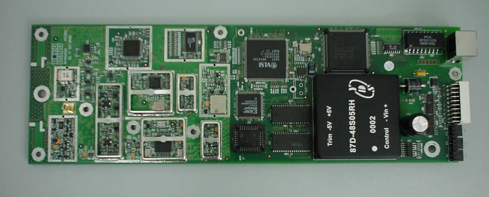
Indoor unit, PCB CS Indoor unit, PCB PS Outdoor unit, PCB CS Outdoor unit, PCB PS
Operational Description
1.1 BreezeNET DS.11 Functional Description The BreezeNET BU-DS.11 and RB-DS.11 can be used as a high speed connection between two remote networks. Figure -1. DS.11 Outdoor Application BU-DS.11 Wireless Base Station The BU-DS.11 is an IEEE 802.11 TGb-compliant base station bridge that is used to connect either a single remote site or multiple remote sites to a central server or Internet connection. It is the central unit for a multipoint configuration and always one side of a point-to-point configuration. The BU-DS.11 comes in two options: the basic unit comes with an antenna integrated on the front cover of the Outdoor unit. In this model, the front cover also functions as a protective sun cover. In BU-DS.11D models with no integral antenna, the unit is provided with one or two antenna connectors (on the Outdoor unit) for connection of one or two external antennas. When this unit is ordered, no antenna is supplied by BreezeCOM and a protective sun cover is mounted on the front of the Outdoor unit. When two antennas are connected to the Outdoor unit, the unit supports the antenna diversity feature. RB-DS.11 Wireless Bridge Client The RB-DS.11 connects a remote Ethernet network to a BU-DS.11 Multipoint Base Station bridge located at a central server or Internet site. It can be programmed to handle up to 1024 MAC addresses. When a station on the Ethernet LAN sends a message that is not destined for a local station, the RB-DS.11 wirelessly forwards the message to the BU-DS.11. When the BU-DS.11 receives a message destined for a station on the RB-DS.11's LAN, the BU-DS.11 wirelessly forwards it to the RB-DS.11. In this manner, the RB-DS.11 and the BU-DS.11 work together like a standard network bridge. The first time each station on the RB-DS.11’s LAN sends a message, the station’s address is registered in the RB-DS.11 and the BU-DS.11. The RB-DS.11 and BU-DS.11 can hold all the addresses necessary to support an entire LAN connected to a RB-DS.11. The RB-DS.11 comes in two options: the basic unit comes with an antenna integrated on the front cover of the Outdoor unit. The RB-DS.11D has no integral antenna, and provides one or two antenna connectors (on the Outdoor unit) for connection of one or two external antennas. When two antennas are connected to the Outdoor unit, the unit supports the antenna diversity feature. Note: The FCC 15.203 requirement prohibits the connection of external antennas with standard N-type connectors. In order to meet this requirement, the external antenna connectors provided on DS.11D models (with no integral antenna) are non-standard, featuring left-handed (counter- clockwise) rotation. Professional Installer (Antennas) WARNING: It is the responsibility of the installer to insure that when using the outdoor antenna kits in the United States (or where FCC rules apply), only those antennas certified with the product are used. The use of any antenna other than those certified with the product is expressly forbidden in accordance to FCC rules CFR47 part 15.204. The installer should configure the output power level of antennas, according to country regulations and per antenna type. For complete information refer to User Manual. Antennas specifications are given below. Specification FLAT PANEL DIRECTIONAL ANTENNA–MT30081(AN1076) THE ANTENNA WILL COMPLY WITH ETSI DE/TM - 4060 , TS2 1. ELECTRICAL FREQUENCY 2.4 – 2.48 GHz GAIN 15.5 dBi MIN VSWR 1.5 : 1 MAX 3 dB BEAMWIDTH 20° TYP POLARIZATION LINEAR, Vertical POWER 2 W INPUT IMPEDANCE 50 Ohms FRONT TO BACK 26 dB 2. MECHANICAL DIMENSIONS 304.8 x 304.8 x 50 mm WEIGHT 1.5 Kg CONNECTOR MCX plug with 20 cm coaxial cable RADOME Plastic,white policarbonate BASE PLATE Aluminum 3. ENVIRONMENTAL TEMPERATURE Operating -40 ° C to + 71 ° C including solar radiation VIBRATION ETS 300 019-1-4 (Feb.92),class 4.1 Sweep rate =0.1 octave/min; 10 cycles SHOCK ETS 300 019-2-2,Table 7 WIND LOAD EN 302-085,Table A.1,Table A.2 (Heavy duty). HUMIDITY ETS 300 019-1-4 EN 302 085 (Annex A.1.1) SALT FOG MIL-STD-810E.Method 509.3 for 200 hours ICE LOADING EN 302-085, Table A.1, Table A.2 (Heavy duty). SOLAR RADIATION ETS 300 019-1-4 SERVICE LIFE > 20 years LIGHTNING PROTECTION DC grounded 10-E-625 9/99 Data/Spec Sheet u ORDER (800) 323-9122 FAX (630) 372-8077 2.4 GHz ISM - MFB Omni-Directional Antenna Series The MAXRAD MFB24004, MFB24006, and MFB24008 are omni-directional base station antennas for ISM applica- tions. They are designed to cover the entire 2.4 ISM frequency band with a VSWR of less than 1.5:1. The antennas have 4, 6, and 8 dBi of gain and their built-in matching networks eliminate the need for a ground plane. The anten- nas can be mounted in a wide variety of locations, including walls, ceilings, and pipes. General Specifications: 2.4 GHz ISM - MFB omni-directional antenna series Radome Material: 5/8 inch diameter pultruded UV-stable fiberglass Termination: N Female Polarization: Vertical Wind Survival: 125 mph Mounting Base Diameter: 1 1/4 inches Maximum Power: 25 watts Mounting Hardware: MMK1924 – L-bracket mount for wall or pipe mount (sold separately) MMK8 - Stainless steel bracket for mast mounting (sold separately) Nominal Impedance: 50 ohms Mounting Hardware MFB24000 Series MMK8MMK1924 erawdraHgnitnuoM seireSannetnAlanoitcerid-inmOBFM-MSIzHG4.2 #ledoMnoitpircseDecirPtsiL 4291KMMretemaidni"2otpufotsamaotrotcennocesabahtiwannetnanagnitnuomrofrognitnuomllawroftekcarb-LleetssselniatS31.31$ 8KMMtsamretemaidmumixam"2aotannetnaretemaid"4/1-1agnitnuomroftekcarbleetssselniatS53.71$ snoitacificepSlacinahceM seireSannetnAlanoitcerid-inmOBFM-MSIzHG4.2 #ledoM talFtnelaviuqE aerAetalP tsurhTlaretaL dniWdetaR@ tnemoMgnidneB dniWdetaR@thgieHthgieWecirPtsiL 40042BFMtf40.0 2 sbl2.3sbl-tf1.1sehcni8sbl43.089.99$ 60042BFMtf50.0 2 sbl5.4sbl-tf2.2sehcni5.11sbl83.016.631$ 80042BFMtf90.0 2 sbl8sbl-tf7.6sehcni02sbl5.008.941$ snoitacificepSlacirtcelE seireSannetnAlanoitcerid-inmOBFM-MSIzHG4.2 #ledoMegnaRycneuqerF denuTyrotcaF ycneuqerFniaG htdiwdnaB RWSV1:5.1@…
Text truncated - open the document above for the full version.
Operational Description
• Brief description The DS11M system is a high speed outdoor Wireless Bridge utilizing the IEEE 802.11b 2.4G Wireless LAN protocol. The DS11M system modem & Radio unit are based on the Intersil PRISIM II chipset. The BU and the RB are combined from the following sub systems (IDU and ODU). The ODU is combined from three sub systems. o DC & protection unit o MAC / controller, clock, low voltage power supply unit o PHY Unit The IDU unit includes the following: • AC2DC power supply unit o AC: 110 or 220V, external fuse, internal AC inlet selector (In from the main line) o DC: 500mA @ 43V (out to the ODU unit) The ODU unit includes the following: • DC2DC converter (switcher). o High voltage DC input: 20 – 70V (48V optimal) o Low voltage DC output: 3A @ 5V • MAC/controller. • PHY (radio & modem). o PRISM 2 chipset ß Base band processor. ß I/Q modulator demodulator which operates at 374MHz ß Tx/Rx SAW filter, 374MHz. ß Up/Down converter. o Power amplifier. o Tx/Rx switch. o Diversity switch. o IF/RF local oscillators. 110V/220V + FUSE IDU Ethernet ODU Integrated Antenna BaseBand Cable Reset RADIO LINK POWER RSSI / Load Eth Link/Act Power/S.T WLAN Act File:Sys_General_Int.vsd Contact & Protection Unit MAC Unit PHY Unit The IDU via the Ethernet port (In/Out) transfers the data. The data and power go (data From/To, power To) from the IDU to the ODU part via the base band Cable. The power goes to the DC2DC converter. The data goes to (from) the MAC unit, which in return moves it to (from) the PHY unit (radio). Tx direction: The base band (data) is the input for the I/Q modulator, which operates at 374MHz. The modulated IF signal (374MHz) passes trough a SAW BPF and then passes to the up converter which takes the modulated IF signal and shifts it to the 2.5GHz band. The RF modulated signal goes trough a power amplifier towards the output via a Tx/Rx switch and 2.4-2.5GHz BPF. The output signal is monitored via a peak detector, which gives the modem a feedback relative to the output power. The modem causes a change in the IF section gain and in return controls the output power. Rx direction: The receiving signal, 2.5GHz band, and pass trough the 2.4-2.5GHz BPF & Tx/Rx switch to a low noise amp. And then through a down converter which shifts the receive frequency to the IF (374MHz). Then the signal passes through the SAW BPF and enters the IF strip amp. and I/Q demodulator where the gain of the IF strip is controlled by the modem in the base band prospector. The modulated signal from the I/Q demodulator is sampled by the modem (A/D operation) and transferred towards the MAC unit. 1. Modulation Types DBPSK, DQPSK, CCK DBPSK Differential Binary Phase Shift Keying DQPSK Differential Quadrature Phase Shift Keying CCK Complementary Code Keying In general we should prefer to work with a CCK modulation since we can transmit 5.5Mbit/Sec or 11Mbit/Sec. Where the DBPSK and DQPSK Modulation types can transmit only 1Mbit/Sec and 2Mbit/Sec respectively. As increasing the bit rate from 1Mbit/sec to 11Mbit/Sec the required Signal to Noise ratio (SNR) become higher. Since the link budget is limited the system shift from one rate to a lower rate automatically to meet the required S/N. 2. Different antenna Types The antenna type that we are using depends in the application. There are 2 kinds of applications: 1) Point To Multi Point (PTMP). 2) Point To Point (PTP). In PTMP applications we can see the base unit (BU) at a center point surrounded by remote bridge (RB) units. In this case the BU antenna will be an OMNI directional antenna (MFB24008) and the RB units antenna will be a directional antenna. In this case we can choose for the RB units two different antennas: An integral antenna (Directional Antenna) or external (Directional Antenna). The difference between the two antennas is the gain where the integral antenna (MT30081) has 15.5dBi gain and the External directional has 24dBi gain. In general we should prefer to work with the integral antenna since it is more cost effective solution. But in a case where we need extra range then we shall use the external directional antenna with the higher gain. In PTP applications both the BU & RB units will use directional antennas which can be integral or external ones and the criteria to use one or other is the same as in the RB units in PTMP applications. There will be occasions where we will be using 2 Directional external antennas. In these occasions the 2 antennas offer us diversity in receiving and help us to overcome propagation problems like fading. Supported standards • Compliant with ETS 300 328 and ETS 300 826 (CE marked) • IEEE 802.11 TGb standard for Wireless LAN at 11 and 5.5 Mbps • IEEE 802.11 standard for 1 and 2 Mbps • Most of the major networking protocols (including IP, IPX) Power Specifications Power Supply Input (via Indoor unit) 207VAC - 253VAC 250mA OR 100VAC - 120VAC 500mA AC Mains option is factory wired. Power Supply Output (from Indoor unit to Outdoor unit) 48VDC Wired LAN Interface Compliant with Ethernet/IEEE 802.3 CSMA/CD Physical interface 10Base-T Connector type RJ-45 Network operating systems All Wireless LAN interface Compliant with IEEE 802.11 Radio Specifications Type Direct sequence spread spectrum Range Europe/ETSI: 15Km USA/FCC: 24Km (15 miles) Transmit power Range: 24dBm (max) to -4dBm (min) Dependable upon Antenna type , system app. & country regulation. Frequency range 2.4-2.4835 Ghz Number of channels Europe: 13 (3 non-overlapping) US: 11 (3 non-overlapping) France: 4 (1 non-overlapping) Sensitivity @ 1Mbps -92dBM, IE-5 BER @ 2Mbps -88dBM, IE-5 BER @ 5.5Mbps -87dBM, IE-5 BER @ 11Mbps -85dBM, IE-5 BER Configuration and Management Configuration and setup SNMP and Windows-based Manager utility Site survey Yes LED indicators Yes SNMP management Yes Specific Features Data rate 11 Mbps 5.5 Mbps 2 Mbps 1Mbps Utility Software BreezeNET Management utility, runs on Windows 95 and Windows NT Size Dimensions (without antennas) TBD Environmental …
Text truncated - open the document above for the full version.
RF Exposure Info
BreezeNET DS.11 Series BU-DS.11 RB-DS.11 User's Guide PRELIMINARYPRELIMINARY July, 2000 Cat 12279903 Rev D Front Matter User’s Guide ii BreezeNET BU-DS.11/RB-DS.11 © 2000 by BreezeCOM Ltd. All rights reserved. No part of this publication may be reproduced in any material form without the written permission of the copyright owner. No part of this publication may be reproduced in any material form without the written permission of the copyright owner. Trade Names BreezeNET and BreezeLINK are trade names of BreezeCOM Ltd. Other brand and product names are registered trademarks or trademarks of their respective companies. Statement of Conditions The information contained in this manual is subject to change without notice. BreezeCOM Ltd. shall not be liable for errors contained herein or for incidental or consequential damages in connection with the furnishing, performance, or use of this manual or equipment supplied with it. Warranty In the following warranty text, “the Company” shall mean: - BreezeCOM Inc., for products located in the USA. - BreezeCOM Ltd., for products located outside the USA. This BreezeNET product is warranted against defects in material and workmanship for a period of one year. During this warranty period the Company will, at its option, either repair or replace products that prove to be defective. For warranty service or repair, the product must be returned to a service facility designated by the Company. Authorization to return products must be obtained prior to shipment. The buyer shall pay all shipping charges to the Company and the Company shall pay shipping charges to return the product to the buyer. The Company warrants that the firmware designed by it for use with the unit will execute its programming instructions when properly installed on the unit. The Company does not warrant that the operation of the unit or firmware will be uninterrupted or error-free. Limitation of Warranty The foregoing warranty shall not apply to defects resulting from improper or inadequate maintenance by the buyer, buyer supplied interfacing, unauthorized modification or misuse, operation outside of the environmental specifications for the product, or improper site preparation Front Matter BreezeNET BU-DS.11/RB-DS.11 iii User's Guide or maintenance. No other warranty is expressed or implied. The Company specifically disclaims the implied warranties of merchantability and fitness for any particular purpose. Electronic Emission Notices This device complies with Part 15 of the FCC rules, ETSI 300-328, UL, UL/C, TUV/GS, and CE. Operation is subject to the following two conditions: 1. This device may not cause harmful interference. 2. This device must accept any interference received, including interference that may cause undesired operation. FCC Radio Frequency Interference Statement This equipment has been tested and found to comply with the limits for a Class B digital device, pursuant to part 15 of the FCC Rules. These limits are designed to provide reasonable protection against harmful interference in a residential installation. This equipment generates, uses and can radiate radio frequency energy and, if not installed and used in accordance with the instructions, may cause harmful interference to radio communications. However, there is no guarantee that interference will not occur in a particular installation. If this equipment does cause harmful interference to radio or television reception, which can be determined by turning the equipment off and on, the user is encouraged to try to correct the interference by one or more of the following measures:<O:P</O:P •1 Reorient or relocate the receiving antenna.<O:P</O:P •2 Increase the separation between the equipment and receiver.<O:P</O:P •3 Connect the equipment into an outlet on a circuit different from that to which the receiver is connected.<O:P</O:P •4 Consult the dealer or an experienced radio/TV technician for help Changes or modifications to this equipment not expressly approved by the party responsible for compliance could void the user’s authority to operate the equipment. FCC Radiation Exposure Statement To comply with FCC radiation exposure limits set forth for an uncontrolled environment, this device should be installed to provide a minimum distance of 30 cm from all persons. Professional Installer (Antennas) WARNING: It is the responsibility of the…
Text truncated - open the document above for the full version.
Contact Information
Applicant
Gennady Furmanov(Senior HW Engineer)
Technical Contact
Non-Technical Contact
BreezeCom Ltd.Itzchak Raiskin
[email protected]972 3645-6243
Test Firm
Hermon Laboratories Ltd.Alexander Usoskin
Technical Specifications
| # | Rule Parts | Frequency Range | Power Output |
|---|---|---|---|
| 1 | 15C | 2.41 GHz - 2.46 GHz | 250.00 mW |
Other Applications from Alvarion Technologies Ltd.

LKTWBSACO12450-1
Jan 05, 2016Outdoor Access Point
Equipment Class
NII - Unlicensed National Information Infrastructure TX
LKTWBSIAC12450-2
Oct 26, 201511ac+abgnAP
Equipment Class
DTS - Digital Transmission System
LKT-COMPACT3X
May 23, 2012Base station transceiver
Equipment Class
TNB - Licensed Non-Broadcast Station Transmitter
LKT-BULTRA-5
Jan 11, 2012BreezeULTRA
Equipment Class
DTS - Digital Transmission System
LKT-DASRU-US
Oct 30, 2011Dual Band Cellular Booster
Equipment Class
PCB - PCS Licensed Transmitter