LLB2019006Water Meter Transponding Unit (MTU)
Aclara Technologies LLC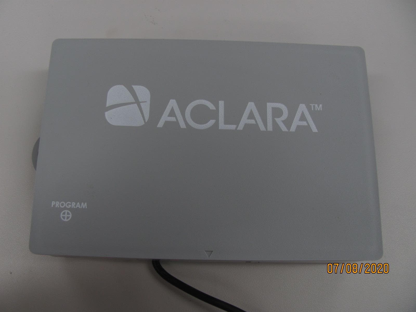
Click to zoom
Application Details
- Equipment Class
- TNB - Licensed Non-Broadcast Station Transmitter
- Date of Grant
- Aug 04, 2020
- Application Purpose
- Original Equipment
- Date of Application
- Aug 04, 2020
- Equipment Note
- Water Meter Transponding Unit (MTU)
- Frequency Range
- 450.00000000 - 470.00000000
- Company
- Aclara Technologies LLC
- Country
- United States
Documents & Files
Document Text
Text extracted from the exhibit documents filed with the FCC. Open a document above to read the original.
Users Manual
A product of Aclara Technologies LLC Confidential and Proprietary Copyright 2020 Aclara. All Rights Reserved. PROPRIETARY NOTICE This document contains information that is private to Aclara Technologies LLC, an Ohio limited liability company, and/or that is private to Aclara Meters LLC, a Delaware limited liability company (individually or collectively “Aclara”). This information may not be published, reproduced, or otherwise disseminated without the express written authorization of Aclara. Any software or firmware described in this document is furnished under a license and may be used or copied only in accordance with the terms of such license. DISCLAIMER The information in this document is subject to change without notice and should not be construed as a commitment by Aclara. Aclara assumes no responsibility for any errors that may appear in this document. No responsibility is assumed for the use or reliability of software on equipment that is not supplied by Aclara. Metrum Cellular, STAR, Synergize, and TWACS are registered trademarks of Aclara Technologies LLC. On-Demand 1.2 Overview1 Technical Brief FCC/ISED Compliance This product/device has been tested and certified to be in compliance with all appropriate requirements of both the FCC and ISED. Any changes or modification to this product/device, or the use of any antenna other than the one provided by or authorized with expressed written approval by Aclara Technologies LLC may void the user's authority to operate this product/device. This product/device and/or its antenna must be fixed-mounted on indoor or outdoor permanent structure(s) providing a separation distance of greater than 20 cm from all persons during normal operation. This device is not designed (and it has no external connection) to operate in conjunction with any other antennas or transmitters. No other operating instructions for satisfying RF exposure compliance are needed. This product/device has been tested and calibrated at the factory. It has no user adjustable controls and can only be adjusted by authorized, trained personnel. Conformité FCC/ISDE Cet équipement a été testé et il est conforme à toutes les exigences appropriées de la FCC et de l'ISDE. Tout changement ou toute modification à cet appareil, ou l’emploi de n’importe quelle antenne autre que celle fournie par ou autorisée sous l’accord exprès donné par écrit d’Aclara Technologies LLC peut annuler l'autorisation d’utiliser de cet appareil. Cet appareil ainsi que son antenne doivent être montés de manière fixe sur des structures intérieures ou extérieures permanentes en conférant une distance d’au moins 20 cm des personnes pendant le fonctionnement normal. Cet appareil n’est pas conçu (et il n'a aucun branchement externe) pour être utilisé en association avec toute autre antenne ou tout émetteur. Aucune autre instruction d’utilisation n’est requise pour assurer la conformité aux règles d’exposition aux RF. Cet appareil a été soumis à des tests et calibré en usine. Il n’a pas de contrôle d’ajustement et ne peut être ajusté que par un personnel autorisé et qualifié. On-Demand 1.2 Overview2 Technical Brief Introduction The Aclara RF™ network is an advanced metering infrastructure or AMI that allows for meter readings to be transmitted directly to a utility along with various system performance and diagnostic information. It allows for unmanned reading of water and gas meters. It is currently deployed in more than 700 utilities worldwide. The three major components of the Aclara RF™ Automated Metering Infrastructure system are: Meter Transmission Units (MTUs) - These are connected to the meter, whether wired to it for water, or physically attached for gas. They take hourly readings from the meter and transmit them via radio frequency on a regular basis. Each meter in the system will have an MTU. Data Collector Units (DCUs) - These are installed in the field to collect readings from nearby MTUs. The DCU performs some treatment and consolidation of these readings and transmits the, typically via cellular service, to the Network Control Computer. AclaraONE - This is the head end, the brain of the system and its command center. It collects all the data from the DCUs in the system, stores it, and uses a web portal to present that data in usable form for the utility. MTUs Aclara’s series 3000 devices connect to the meter, record readings hourly, and store them in memory. They can hold 12 readings in memory, and every 6 hours they transmit those readings via radio frequency to nearby DCUs. Since the MTU can hold no more than 12 readings, each hour a new reading is added to memory and the oldest reading, the one that is 13 hours old, drops off. Because MTUs transmit 12 readings every 6 hours, there is redundancy in the readings transmitted. The first 6 readings from the 6:00 a.m. transmission will be the last 6 readings in the noon transmission. By the 6:00 p.m. transmission, those 6 readings will have been replaced by 6 newer readings. This redundancy means that if a transmission fails to reach the DCU for whatever reason, the readings still have a second chance in the next transmission. Duplicate readings are filtered by the DCU, so only a single hourly reading is transmitted to AclaraONE. Water and gas MTUs differ slightly in the way they connect to the meter. Gas MTUs are attached to the face of the gas meter, and consequently cannot be repositioned. (Meter-specific gas meter installation instructions are also available on Aclara Connect.) A water MTU is connected to the meter register by means of a three-wire cable. Because water meters may be installed indoors in cold climates, and either outdoors or in pits in warm climates, the length of the cable allows for some flexibility in placement of the MTU for optimum radio signal propagation. On-Demand 1.2 Overview3 Technical Brief Users may find additional information on water MTUs in the Water MTU Field Guide, Y20376-TRD. Refer to the MTU Installation Instructi…
Text truncated - open the document above for the full version.
Cover Letter(s)
77 West Port Plaza Drive Suite 500 St. Louis, MO 63146-3126 Aclara.com 1-800 895 6400 314 895 7373 fax July 20, 2020 Federal Communications Commission Authorization and Evaluation Division 1435 Oakland Mills Road Columbia, MD 21046 Innovation, Science, and Economic Development Canada Certification and Engineering Bureau P.O. Box 11490, Station ‘H’ 3701 Carling Ave., Building 94 Ottawa, Ontario K2H 8S2 Canada Date: SUBJECT: Application for FCC ID: LLB2019006 Application for ISED ID: 4546A-2019006 To Whom It May Concern: Aclara Technologies LLC hereby authorizes Joseph Strzelecki of Radiometrics Midwest Corp at 12 Devonwood Ave, Romeoville, IL 60446 on its behalf, to apply to the Federal Communications Commission and Innovation, Science, and Economic Development Canada for our equipment. Any and all acts carried out by Radiometrics on our behalf shall have the same effect as acts of our own. This is to advise that we are in full compliance with the Anti- Drug Abuse Act. Aclara Technologies LLC is not subject to a denial of federal benefits pursuant to Section 5301 of the Anti-Drug Act of 1988, 21 USC853a, and no party to the application is subject to a denial of federal benefits pursuant to that section. This authorization is valid until further written notice from the applicant. Regards, Aclara Technologies, LLC 77 Westport Plaza Drive, Suite 500 St. Louis, Missouri 63146 PH: 314-895-8012 Email: [email protected]
Cover Letter(s)
Page 1 of 1 RP-9272AL 12 Devonwood Ave SOL VING A WAV E OF EMI COMP LIANCE PR OB LE MS Romeoville, IL 60446 Tel: (815) 293-0772 Federal Communications Commission July 13, 2020 Authorization and Evaluation Division 7435 Oakland Mills Rd. Columbia, MD 21046 Reference FCC ID: LLB2019006 Organization: Aclara Technologies, LLC. 1. Long Term Confidentiality Pursuant to Sections 0.457 and 0.459 of the Commission’s Rules, (Aclara Technologies, LLC) hereby requests long-term confidential treatment of information accompanying this application as outlined below: Exhibit Type File Name Circuit Schematics 7 Aclara Schematics 9272 Block Diagram 8 Aclara Block Diagram 9272 EUT description (Operational Description) 10 Operational Description 9272 Parts List 17 Aclara Parts List 9272 The above materials contain trade secrets and proprietary information not customarily released to the public. The public disclosure of these materials may be harmful to the applicant and provide unjustified benefits to its competitors. The applicant understands that pursuant to Section 0.457 of the Rules, disclosure of this application and all accompanying documentation will not be made before the date of the Grant for this application. Pursuant to DA04-1705 June 15, 2004 of the Commission’s public notice, we also request temporary confidential treatment of information accompanying this application as outlined below: Exhibit Type File Name Internal Photos 4 Internal Photos 9272 User Manual 14 Aclara On-Demand 1.2 User Manual 9272 Please hold confidential for 90 days Authorized Signature Joseph Strzelecki Senior EMC Engineer Radiometrics Midwest Corporation Authorized Agent for Aclara Technologies LLC.
Cover Letter(s)
Page 1 of 1 RP-9272AL 12 East Devonwood SOLVING A WAVE OF EMI COMPLIANCE PROBLEMS Romeoville, IL 60446 Tel: (815) 293-0772 Fax: (815) 293-0820 July 10, 2020 Federal Communications Commission Authorization and Evaluation Division 7435 Oakland Mills Rd. Columbia, MD 21046 Reference FCC ID: LLB2019006 Organization: Aclara Technologies, LLC. 77 Westport Plaza Drive, Suite 500 Saint Louis, MO 63146 STATEMENT CONCERNING COMPLIANCE WITH SECTION 90.203(J)(5) Introduction Section 90.203 (j)(5) of the Commission’s Rules on transmitters provides, in pertinent part: If the equipment [421-512 MHz bands] is capable of transmitting data and has an overall bandwidth of 6.25 kHz or more, the equipment must be capable of supporting a minimum data rate of 4800 bits per second per 6.25 kHz of bandwidth. Justification The model 2019-006 radio transceiver submitted is used as a part of a utility meter reading system. The 2019-006 transmitter sends data with a 2GFSK modulation at a rate of 7232 bps. The emissions designator is 9K66F1D. As the 2019-006 does transmit at 7232 bps with a bandwidth of 7.4 kHz, it is capable of supporting a minimum data rate of 4800 bits per second per 6.25 kHz of bandwidth. Authorized Signature Joseph Strzelecki Senior EMC Engineer Radiometrics Midwest Corporation Authorized Agent for Aclara Technologies, LLC.
Cover Letter(s)
Page 1 of 1 RP-9272AL 12 East Devonwood SOLVING A WAVE OF EMI COMPLIANCE PROBLEMS Romeoville, IL 60446 Tel: (815) 293-0772 Fax: (815) 293-0820 July 29, 2020 Federal Communications Commission Authorization and Evaluation Division 7435 Oakland Mills Rd. Columbia, MD 21046 Reference FCC ID: LLB2019006 Organization: Aclara Technologies, LLC. 77 Westport Plaza Drive, Suite 500 Saint Louis, MO 63146 Subject: Frequency Justification Attestation Aclara Technologies LLC acknowledges that this device will not be marketed to USA users with frequency bands which are not allowed by rule part 90, and that it is a violation of FCC rules if this device is operated on unauthorized frequencies inside the United States. Aclara Technologies LLC, acknowledges that this equipment meets the requirement of FCC Rules, Part 90.203(g)(3). Programming of this product’s transmit frequencies can be performed only by the manufacturer or by authorized service or maintenance personnel. This equipment can only be programmed for frequencies through use of external devices or specifically programmed modules made available only to authorized service or maintenance personnel, not the end user or the general public. This transmitter operates in the following frequency ranges: Band/Mode Frequency ranges FCC rule parts UHF 450 - 470 MHz 90 Aclara Technologies is requesting that the FCC lists the above applicable frequency range under FCC Rule Part 90 on the FCC Grant. For the FCC’s Rule Part 90 application, this radio is used in public utilities as indicated in the table below. This device complies with 47 CFR Part 90.203(e), the end user cannot program the transmit frequencies, since it is a sealed device. Per the FCC’s KDB634817 guidance, as an alternative to listing the exact frequencies, we acknowledge that it is a violation of the FCC Rules if this device operates on unauthorized frequencies. Frequency Range (MHz) Part 90 450-454 X 454-456 456-460 X 460-462.5375 X 462.5375-462.7375* 462.7375-467.5375 X 467.5375-467.7375 X 467.7375-470 X * Canada This device will only be used in the designated Frequency Ranges above that are marked with an X. Authorized Signature Joseph Strzelecki Senior EMC Engineer Radiometrics Midwest Corporation Authorized Agent for Aclara Technologies, LLC.
External Photos
Authorized Agent: Radiometrics Midwest Corporation (815) 293-0772 External EUT Photographs Front of EUT The Enclosure is 7.25 inches wide x 4.25 inches tall x 1.5 inches deep Authorized Agent: Radiometrics Midwest Corporation (815) 293-0772 Left Side of EUT Right Side of EUT Authorized Agent: Radiometrics Midwest Corporation (815) 293-0772 Top of EUT Bottom of EUT Authorized Agent: Radiometrics Midwest Corporation (815) 293-0772 Back of EUT
ID Label/Location Info
Authorized Agent: Radiometrics Midwest Corporation (815) 293-0772 ID Label/Location Photograph showing placement of Label This is the bottom of the case of the product. Photographs of labels FCC/ISED ID label: Label Dimensions: 1 inch x 0.5 inches The label is a 3 mil, gloss white polyester material. The labeled is applied using an acrylic permanent adhesive. Format of Label: Radiometrics Midwest Corporation (815) 293-0772 – [email protected] Photograph showing placement of model label on left side of Case The HVIN/Model is 2019-006. It is just above the IC #. Description of Label The label is a 3 mil, gloss white polyester material. The label is applied using acrylic permanent adhesive. The label is UL/CSA approved for indoor/outdoor use. The label is 1 x 4 inches.
Internal Photos
Internal EUT Photographs Photograph of PC Board: Component Side Photograph of PC Board: Cage Removed Photograph of PC Board: Shield Removed Photograph of PC Board: Foil Side Photograph of PC Board: Foil Side, Batteries Removed
RF Exposure Info
Authorized Agent: Radiometrics Midwest Corporation (815) 293-0772 RF Exposure FCC ID: LLB2019006 This calculation is based on the highest EIRP possible from the EUT considering maximum power and antenna gain. The highest output power of the EUT is 0.794 W and the max gain of the antenna is 3 dBi. There is a firmware control duty cycle. The firmware is set to limit duty cycle at 40% duty cycle or less in any given 6-minute period. In most cases, the duty cycle is much less than 40%. For all calculations, 40% will be used as a worst-case in any given 6-minute period, as this is a worst case. 1.0 RF EXPOSURE PER FCC 1.1310 MHz Max Power dBm Max Ant Gain dBi Duty Cycle % EIRP Watts (S) GP Limit mW/cm^2 Declared Minimum seperation Distance (cm) EUT power Density mW/cm2 Result 450 29.00 3 40 0.634 0.300 20.0 0.126 Pass 460 28.85 3 40 0.612 0.307 20.0 0.122 Pass 470 28.90 3 40 0.620 0.313 20.0 0.123 Pass Notes on the above table: a. S is the power density General Population Limit from FCC 1.1310 Table 1 b. EIRP Power is the Peak Effective Radiated Power. EIRP = (Average Conducted Power + Antenna gain) * Duty Cycle. Since the calculated power density is less than the limit, this product fully meets the OET 65 requirements for the general population.
Test Report
Radiometrics Midwest Corporation (815) 293-0772 – www.radiomet.com Page 1 of 32 Electromagnetic Compatibility Test Report Tests Performed on an Aclara Technologies, LLC Water Meter Transmission Unit (MTU), Model: 2019-006 Radiometrics Document RP-9272A Product Detail: FCC ID: LLB2019006 IC: 4546A-2019006 Equipment type: 450-470 MHz Transceive r Test Standards: US CFR Title 47, Chapter I, FCC Part 2 and 90 FCC Parts 2, 15, and 90 CFR Title 47: 2019 IC RSS-119 Issue 12: 2015 IC RSS-GEN Issue 4: 2014 Tests Performed For: Test Facility: Aclara Technologies, LLC 77 Westport Plaza Drive, Suite 500 Saint Louis, MO 63146 Radiometrics Midwest Corporation 12 Devonwood Av. Romeoville, IL 60446 Phone: (815) 293-0772 Test Dates: April 8 to 22 and August 13-14, 2020 Document RP-9272A Revisions: Rev. Issue Date Affected Sections Revised By 0 July 16, 2020 1 July 21, 2020 3.1, 4.2, 10.1 Joseph Strzelecki 2 August 17, 2020 10.4.2 & 10.7.2 Joseph Strzelecki Radiometrics Midwest Corporation Test Report for the Aclara, Water MTU, Model 2019-006 RP-9272A Rev. 2 Page 2 of 46 Table of Contents 1 ADMINISTRATIVE DATA .................................................................................................................... 3 2 TEST SUMMARY AND RESULTS ...................................................................................................... 3 3 EQUIPMENT UNDER TEST (EUT) DETAILS ..................................................................................... 4 3.1 EUT Description ............................................................................................................................ 4 4 TESTED SYSTEM DETAILS ............................................................................................................... 4 4.1 Tested System Configuration ........................................................................................................ 4 4.2 Special Accessories ...................................................................................................................... 5 4.3 Equipment Modifications ............................................................................................................... 5 5 TEST SPECIFICATIONS AND RELATED DOCUMENTS .................................................................. 5 6 RADIOMETRICS’ TEST FACILITIES .................................................................................................. 5 7 DEVIATIONS AND EXCLUSIONS FROM THE TEST SPECIFICATIONS ......................................... 6 8 CERTIFICATION ................................................................................................................................. 6 9 TEST EQUIPMENT TABLE ................................................................................................................. 6 10 TEST SECTIONS .............................................................................................................................. 7 10.1 Peak Output Power ..................................................................................................................... 7 10.2 Occupied Bandwidth; Emissions Masks ..................................................................................... 8 10.2.1 Conducted Spurious Emissions .......................................................................................... 27 10.3 Occupied Bandwidth ................................................................................................................. 28 10.4 Field Strength of Unwanted Spurious Radiation ....................................................................... 32 10.4.1 Test Procedures ................................................................................................................. 32 Figure 1. Drawing of Radiated Emissions Setup ........................................................................... 33 10.4.2 Spurious Radiated Emissions Test Results ........................................................................ 34 10.5 Frequency Stability .................................................................................................................... 36 10.5.1 Frequency Stability Vs Temperature .................................................................................. 36 10.5.2 Frequency Stability Vs Supply Voltage ............................................................................... 36 10.5.3 Test Results for Frequency Stability ................................................................................... 36 10.6 Transient Frequency Behavior .................................................................................................. 37 10.6.1 Test method ........................................................................................................................ 37 10.6.2 Limits of transient frequency ............................................................................................... 37 10.6.3 Test Results ........................................................................................................................ 38 10.6.4 Results for Time Periods t1 and t2 ..................................................................................... 38 10.6.5 Results for Time Period between t2 and t3......................................................................... 40 10.6.6 Results for Time Period t3 .................................................................................................. 42 10.7 Radiated Emissions (Receive Mode) ........................................................................................ 44 10.7.1 Radiated Emissions Field Strength Sample Calculation .................................................... 44 10.7.2 Spurious Radiated Emissions Test Results (Receive Mode) ............................................. 44 11 MEASUREMENT INSTRUMENTATION UNCERTAINTY .................... ........................................... 46 Notice: This…
Text truncated - open the document above for the full version.
Test Setup Photos
Authorized Agent: Radiometrics Midwest Corporation (815) 293-0772 Test Setup Photographs Photographs of Radiated Emissions Test Setup 30 - 200 MHz (FCC-ISED) Authorized Agent: Radiometrics Midwest Corporation (815) 293-0772 200 - 1000 MHz Authorized Agent: Radiometrics Midwest Corporation (815) 293-0772 1-5 GHz
Contact Information
Applicant
John Cunningham(VP, Chief Engineer)
Test Firm
Radiometrics Midwest Corp.Joseph Strzelecki
Technical Specifications
| # | Rule Parts | Frequency Range | Power Output | Emission | Tolerance |
|---|---|---|---|---|---|
| 1 | 90 | 450 MHz - 470 MHz | 794.00 mW | 7K40F1D | 0.5200000000 ppm |
Other Applications from Aclara Technologies LLC
LLB-095370
Jun 18, 2026Wireless Current Sensor for Capacitor Bank Applications
Equipment Class
DTS - Digital Transmission System
LLBY84092-1
Nov 10, 2022RF Endpoint
Equipment Class
TNB - Licensed Non-Broadcast Station Transmitter
LLB2020001
Apr 04, 2022Aclara Core Module transceiver
Equipment Class
TNB - Licensed Non-Broadcast Station Transmitter
LLB2015001
Dec 10, 2015Series 4000 MTU
Equipment Class
TNB - Licensed Non-Broadcast Station Transmitter
LLBY84000
Sep 28, 2015Synergize RF network utility I210+ meter transponder
Equipment Class
TNB - Licensed Non-Broadcast Station Transmitter