LLB2020001Aclara Core Module transceiver
Aclara Technologies LLC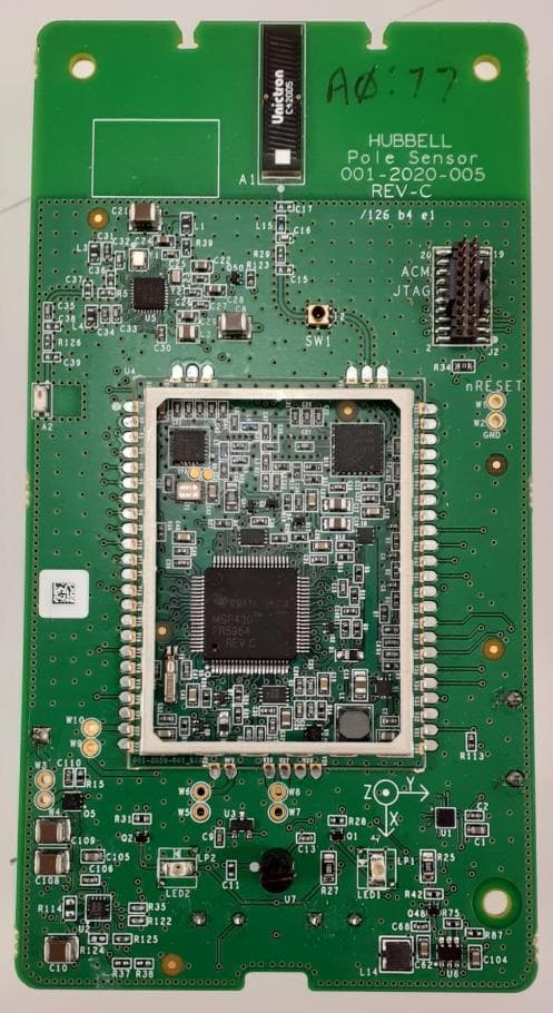
Click to zoom
Application Details
- Equipment Class
- TNB - Licensed Non-Broadcast Station Transmitter
- Date of Grant
- Apr 04, 2022
- Application Purpose
- Original Equipment
- Date of Application
- Apr 04, 2022
- Equipment Note
- Aclara Core Module transceiver
- Frequency Range
- 450.00000000 - 470.00000000
- Company
- Aclara Technologies LLC
- Country
- United States
Documents & Files
Document Text
Text extracted from the exhibit documents filed with the FCC. Open a document above to read the original.
Users Manual
Aclara Core Module Implementation Requirements Aclara RF Technologies LLC 30400 Solon Road Solon, OH 44139 D. Batey The information in this document will provide guidance on proper implementation of the Aclara Core Module (ACM). The ACM is a fully contained MCU system with RF circuitry and regulated supplies that can be used on Aclara’s proprietary end point devices to support Aclara’s RF network. Proper RF performance, within Aclara’s licensed operating frequency band of 450MHz to 470MHz, can be achieved by following a few design guidelines. The 1.5” x 2.0” package requires no connectors and is placed and soldered down as a surface mount device during production. With the module implemented properly, there is no need for repeating FCC transmitter tests, saving both time and cost of final device certifications. ACM Pinout ACM Pin Signal Description Radio Pin# Signal Name Function I/O Type Level V1 GND V2 P3.4 MCU GPIO Digital I/O 3.3V V3 P3.5 MCU GPIO Digital I/O 3.3V V4 P3.6 MCU GPIO Digital I/O 3.3V V5 P3.7 MCU GPIO Digital I/O 3.3V V6 P4.4 MCU GPIO Digital I/O 3.3V V7 P2.4 MCU SPI CLK Digital Output 3.3V V8 P5.4 CTS Digital Input 3.3V V9 P5.5 RTS Digital Output 3.3V V10 P1.1 MCU GPIO Digital I/O 3.3V V11 P2.7 XL nCS Digital Output 3.3V V12 P5.6 XL INT1 Digital Input 3.3V V13 P5.7 XL INT2 Digital Input 3.3V V14 P6.4 SDA Digital Bi-Dir 3.3V V15 P6.5 SCL Digital Output 3.3V V16 P6.6 MCU GPIO Digital I/O 3.3V V17 P6.7 MCU GPIO Digital I/O 3.3V V18 P1.0 MCU GPIO Digital I/O 3.3V V19 P6.0 MCU GPIO Digital I/O 3.3V V20 P6.1 MCU GPIO Digital I/O 3.3V V21 P6.2 MCU GPIO Digital I/O 3.3V V22 VCORE VCORE 3.3V Output Voltage Power Output 3.3V V23 GND Ground V24 GND Ground V25 VBAT_LO VBAT Low Current Voltage Input Power Input 3.6V V26 VBAT_HI VBAT High Current Voltage Input Power Input 3.6V V27 VBAT_HI VBAT High Current Voltage Input Power Input 3.6V V28 GND Ground V29 GND Ground V30 GND Ground V31 P8.0 MCU GPIO Digital I/O 3.3V V32 P1.4 B WAKE Digital Output 3.3V V33 P3V6 3.6V RF Power Supply Output Power Output 3.6V V34 TDO JTAG Test Data Output Digital Output 3.3V V35 TDI JTAG Test Data Input Digital Input 3.3V V36 TMS JTAG Test Mode Select Digital Input 3.3V V37 TCK JTAG Test Clock Digital Input 3.3V V38 P7.7 MCU GPIO Digital I/O 3.3V V39 P4.0 MCU GPIO Digital I/O 3.3V V40 P4.2 B RESET Digital Output 3.3V V41 P2.5 SPI MOSI Digital Output 3.3V V42 P2.5 SPI MISO Digital Input 3.3V V43 MSP TEST MCU TEST Input Digital Input 3.3V V44 MSP NMI MCU nRESET/NMI Input Digital Input 3.3V V45 P8.1 MCU GPIO Digital I/O 3.3V V46 P2.0 TXD Digital Output 3.3V V47 P2.1 RXD Digital Input 3.3V V48 RX0 TX1 RF PA RX/TX Control Input Digital Input 3.3V V49 SKY EN RF PA Enable Control Input Digital Input 3.3V V50 P8.2 ACM WAKE Digital Input 3.3V V51 P8.3 MCU GPIO Digital I/O 3.3V V52 GND Ground V53 GND Ground V54 ANT RF Antenna Output RF Output V55 GND Ground V56 GND Ground V57 NC No Connect V58 GND Ground Design Guidelines Power Supply : The ACM is designed to be operated at a nominal input voltage of 3.6VDC. The actual operating input voltage of the ACM can vary from a minimum of 2.8VDC to a maximum of 3.8VDC. This wide range of input voltage supports designs powered from a primary battery source. There are two voltage inputs, one for high current and one for low current. They can be powered from different battery sources if needed. The low current input voltage, VBAT_LO, provides power for the MCU and its peripherals. The high current input voltage, VBAT_HI, provides power for the RF circuitry and the regulated supply. The regulated supply can draw up to 1.0 Amp of current while providing a regulated 3.6VDC supply to the RF circuitry. This regulated supply assures consistent RF power levels over the entire range of input voltage. Antenna : The ACM antenna output shall connect to a host board strip-line that provides a 50 ohm controlled impedance path to an antenna. The strip-line can connect to a RF connector in order to support an external (off-board) antenna or it can connect to an etched (on-board) antenna with a matching network to provide the proper 50 ohm termination for the strip-line. The ACM’s maximum RF output level is 30dBm (1 Watt) of RF power. There is a maximum gain limit of +5dBi for the ACM antenna. Antenna placement shall be at least 100cm from any operator. Antenna type shall be EM Wave 073-0010 or equivalent. Host Board Stackup : The Host PCB stackup shall be at least a 2-layer stackup with an overall thickness of 0.062” +/- 0.005” and use a minimum copper weight of 1/4oz. Ground flooding is allowed underneath the ACM module to provide further isolation from any digital interference. The ACM is a surface mount device (SMD) that uses castellated vias for pins and can be reflowed along with other SMD devices. High temperature board materials, such as Isola 410 or FR-408, with Tg ratings of 170C minimum shall be used to maintain coplanarity. This information should be enough to assure a proper installation of the ACM into any new Aclara end point device that requires 450MHz to 470MHz licensed narrow band RF transmission. PCB Footprints and mechanical drawings can be provided by Aclara Engineering. Label Requirements : The ACM requires a label on the product case that includes Bluetooth ID, model number and FCC ID numbers. The label must be easy to view and can include bar codes. An example label is shown in Figure 2. FCC/IC : Pursuant to FCC 15.21 of the FCC rules, changes not expressly approved by Aclara Technologies LLC might cause harmful interference and void the FCC authorization to operate this product. Warning : The antennas used for this transmitter must be installed to provide a separation distance greater than 25 cm from all persons. Ce produit est conforme à la norme FCC et aux limites d'exposition au rayonnement RSS-102 d'Industrie Canada définies pour un environnement non contrôlé. Compliance : This device complies with Part 15 of the FCC Rules and Innovation, Science and Economic Deve…
Text truncated - open the document above for the full version.
Cover Letter(s)
Attention: All of the files are in zip files with folders. Enclosed is the FCC submittal for Aclara Technologies. Radiometrics Midwest will be paying Timco for filing the submittal. FCC ID: LLB2020001 John Cunningham item # AdminTech 1 ID Drawing and Location1 ID-Label 9571AYY No 2 Measurement Test Report 2 Aclara 9571A Part 90-ISED ReportYY No 3 RF Exposure FCC3 RF Exposure FCC 9571AYY No 4 Internal Photos of EUT 4 Aclara Internal Photos 9571AYY No 5 External Photos of EUT 5 External Photos 9571AYY No 6 Test Setup Photos6 Setup-Photos 9571AYY No 7 Schematic diagrams 7 ACM_Schematic 9571AYY Yes 8 Block Diagram 8 ACM Block Diagram 9571AYY Yes 9 Users manual9 Aclara Core Module User ManualYY No Compliance statements on pages 6, 7 10 Operational Description of the EUT 10 ACM Operational DescriptionYY Yes 11 Tune Up Procedures11 Tune up ProceduresYY No 12 731 form12 Aclara 731_TCB 9571AYY No 13 Letter of Authorization to Radiometrics 13 Aclara Core Module Auth-Ltr 9571AYY No 14 Request for Confidentiality Letter14 Aclara Confidentiality letter 9571AYY No 15 spectral efficiency letter 15 Description of spectral efficiency 9571AYY No 16 Frequency Justification 16 Aclara Frequency Justification Ltr 9571AYY No 17 Parts List17 ACM_BOM 9571AYY Yes 18 Modular Approval Letter18 Mod Approval ltr FCC 9571AYY Yes Sincerely yours, Joseph Strzelecki Senior EMC Engineer Radiometrics Midwest Corporation is an authorized agent of Aclara Technologies Exhibit List Exhibit DescriptionFile Name RMC Review ConfNotes FCC grantee contact:
Cover Letter(s)
Page 1 of 1 12 Devonwood Ave SOL VING A WAV E OF EMI COMP LIANCE PR OB LE MS Romeoville, IL 60446 Tel: (815) 293-0772 Federal Communications Commission Authorization and Evaluation Division REFERENCE March 9, 2022 FCC ID: LLB2020001 RE: Request for Limited Modular Approval APPLICANT: Aclara Technologies, LLC. Item Modular approval Requirement Meets Justification (1) The radio elements must have the radio frequency circuitry and must be shielded. Physical/discrete and tuning capacitors may be located external to the shield but must be on the module assembly. No The ACM module fully complied with all standards without a shield over the RF section. The module does not depend on any other shielding. (2) The module shall have buffered modulation/data input(s) (if such inputs are provided) to ensure that the module will comply with the requirements set out in the applicable FCC rules with any type of input signal. Yes The SPI interface uses buffered CMOS inputs and outputs. There is a 64-byte TX/RX FIFO buffer internal to the Si4467. The SPI Interface only allows data transfer to the transceiver and has no effect on the modulation or data rate of the RF transmitted signal. (3) The module shall have its own power supply regulation on the module. This is to ensure that the module will comply with the requirements set out in the applicable standard regardless of the design of the power supplying circuitry in the host device which houses the module. Yes The Host Board power supply shall provide a regulated 3.6 VDC output voltage with less than 20mVAC of ripple. The power supply shall be capable of supplying up to 1.0 Amp of current and regulate the 3.6V output voltage to +/- 5% tolerance (4) The module must contain a permanently attached antenna, or contain a unique antenna connector, and be marketed and operated only with specific antenna(s), per §§ 15.203, 15.204(b), 15.204(c), 15.212(a), 2.929(b); Yes The product is professionally installed only. The installations are controlled by Aclara. Only approved antennas will be used. No External amplifiers will be used. The product will not be sold to the general public. (5) The module shall be tested for compliance with the applicable standard in a stand-alone configuration, i.e. the module must not be inside another device during testing. Yes The product was tested with an external power supply with no additional filtering. The product was tested on a representative PCB that had no additional shielding. (6) The module must be labeled with its permanently affixed FCC ID label, or use an electronic display (see KDB Publication 784748) Yes The FCC ID label format is included in the filing. The product will always be inside another enclosure during actual use. (7) The module must comply with all specific rules applicable to the transmitter, including all the conditions provided in the integration instructions by the grantee Yes It is only professionally installed by utility companies. It will not be sold to the general public. Aclara will control the end product into which the module will be installed and will be maintained, such that full compliance of the end product is always ensured. (8) The module must comply with RF exposure requirements Yes Refer to RF exposure Exhibit. The transmitter meets MPE calculations of 47 CFR 1.1310. Aclara will only sell the RF module while connected to Aclara products. Radiometrics has been authorized by Aclara Technologies, LLC to act as an agent in the preparation of their submittal request for Modular Approval. Sincerely, Joseph Strzelecki Senior EMC Engineer Radiometrics Midwest Corporation Authorized Agent for Aclara Technologies, LLC. E-Mail: [email protected]
Cover Letter(s)
Page 1 of 1 RP-9571A 12 East Devonwood SOLVING A WAVE OF EMI COMPLIANCE PROBLEMS Romeoville, IL 60446 Tel: (815) 293-0772 Fax: (815) 293-0820 March 16, 2022 Federal Communications Commission Authorization and Evaluation Division 7435 Oakland Mills Rd. Columbia, MD 21046 Reference FCC ID: LLB2020001 Organization: Aclara Technologies, LLC. 77 Westport Plaza Drive, Suite 500 Saint Louis, MO 63146 Subject: Frequency Justification Attestation Aclara Technologies LLC acknowledges that this device will not be marketed to USA users with frequency bands which are not allowed by rule part 90, and that it is a violation of FCC rules if this device is operated on unauthorized frequencies inside the United States. Aclara Technologies acknowledges that this equipment meets the requirement of FCC Rules, Part 90.203(g)(3). Programming of this product’s transmit frequencies can be performed only by the manufacturer or by authorized service or maintenance personnel. This equipment can only be programmed for frequencies through use of external devices or specifically programmed modules made available only to authorized service or maintenance personnel, not the end user or the general public. This transmitter operates in the following frequency ranges: Band/Mode Frequency ranges FCC rule parts UHF 450 - 470 MHz 90 Aclara Technologies is requesting that the FCC lists the above applicable frequency range under FCC Rule Part 90 on the FCC Grant. For the FCC’s Rule Part 90 application, this radio is used in public utilities as indicated in the table below. This device complies with 47 CFR Part 90.203(e), the end user cannot program the transmit frequencies, since it is a sealed device. Per the FCC’s KDB 634817 guidance, as an alternative to listing the exact frequencies, we acknowledge that it is a violation of the FCC Rules if this device operates on unauthorized frequencies. Frequency Range (MHz) Part 90 450-454 X 454-456 456-460 X 460-462.5375 X 462.5375-462.7375* 462.7375-467.5375 X 467.5375-467.7375 X 467.7375-470 X * Canada This device will only be used in the designated Frequency Ranges above that are marked with an X. Authorized Signature Joseph Strzelecki Senior EMC Engineer Radiometrics Midwest Corporation Authorized Agent for Aclara Technologies, LLC.
Cover Letter(s)
Page 1 of 1 RP-9571A 12 East Devonwood SOLVING A WAVE OF EMI COMPLIANCE PROBLEMS Romeoville, IL 60446 Tel: (815) 293-0772 Fax: (815) 293-0820 March 17, 2022 Federal Communications Commission Authorization and Evaluation Division 7435 Oakland Mills Rd. Columbia, MD 21046 Reference FCC ID: LLB2020001 Organization: Aclara Technologies, LLC. 77 Westport Plaza Drive, Suite 500 Saint Louis, MO 63146 STATEMENT CONCERNING COMPLIANCE WITH SECTION 90.203(J)(5) Introduction Section 90.203 (j)(5) of the Commission’s Rules on transmitters provides, in pertinent part: If the equipment [421-512 MHz bands] is capable of transmitting data and has an overall bandwidth of 6.25 kHz or more, the equipment must be capable of supporting a minimum data rate of 4800 bits per second per 6.25 kHz of bandwidth. Justification The model 101-2020-001 radio transceiver submitted is used as a part of a utility meter reading system. The 101-2020-001 transmitter sends data with a 2GFSK modulation at a rate of 7232 bps. The emissions designator is 7K50F1D. As the 101-2020-001 does transmit at 7232 bps with a bandwidth of 7.5 kHz, it is capable of supporting a minimum data rate of 4800 bits per second per 6.25 kHz of bandwidth. Authorized Signature Joseph Strzelecki Senior EMC Engineer Radiometrics Midwest Corporation Authorized Agent for Aclara Technologies, LLC.
Cover Letter(s)
Page 1 of 1 RP-9571AL 12 Devonwood Ave SOL VING A WAV E OF EMI COMP LIANCE PR OB LE MS Romeoville, IL 60446 Tel: (815) 293-0772 Federal Communications Commission March 25, 2022 Authorization and Evaluation Division 7435 Oakland Mills Rd. Columbia, MD 21046 Reference FCC ID: LLB2020001 Organization: Aclara Technologies, LLC. 1. Long Term Confidentiality Pursuant to Sections 0.457 and 0.459 of the Commission’s Rules, (Aclara Technologies, LLC) hereby requests long-term confidential treatment of information accompanying this application as outlined below: Exhibit Type File Name Circuit Schematics 7 ACM_Schematic 9571A EUT description (Operational Description) 10 ACM Operational Description Parts List 17 ACM_BOM 9571A The above materials contain trade secrets and proprietary information not customarily released to the public. The public disclosure of these materials may be harmful to the applicant and provide unjustified benefits to its competitors. The applicant understands that pursuant to Section 0.457 of the Rules, disclosure of this application and all accompanying documentation will not be made before the date of the Grant for this application. Authorized Signature Joseph Strzelecki Senior EMC Engineer Radiometrics Midwest Corporation Authorized Agent for Aclara Technologies LLC.
Cover Letter(s)
77 West Port Plaza Drive Suite 500 St. Louis, MO 63146-3126 Aclara.com 1-800 895 6400 314 895 7373 fax March 14, 2022 Federal Communications Commission Authorization and Evaluation Division 1435 Oakland Mills Road Columbia, MD 21046 Innovation, Science, and Economic Development Canada Certification and Engineering Bureau P.O. Box 11490, Station ‘H’ 3701 Carling Ave., Building 94 Ottawa, Ontario K2H 8S2 Canada Date: SUBJECT: FCC Application for LLB2020001 and IC 4546A-2020001 To Whom It May Concern: Aclara Technologies LLC hereby authorizes Joseph Strzelecki of Radiometrics Midwest Corp at 12 Devonwood Ave, Romeoville, IL 60446 on its behalf, to apply to the Federal Communications Commission on our equipment. Any and all acts carried out by Radiometrics on our behalf shall have the same effect as acts of our own. This is to advise that we are in full compliance with the Anti- Drug Abuse Act. Aclara Technologies LLC is not subject to a denial of federal benefits pursuant to Section 5301 of the Anti-Drug Act of 1988, 21 USC853a, and no party to the application is subject to a denial of federal benefits pursuant to that section. This authorization is valid until further written notice from the applicant. Regards, Recoverable Signature X John N Cunningham VP - Chief Engineer Signed by: f3ec76e8-21a9-4d49-a1a4-25409f7cb114 Aclara Technologies, LLC 77 Westport Plaza Drive, Suite 500 St. Louis, Missouri 63146 PH: 314-895-8012 Email: [email protected]
External Photos
Authorized Agent: Radiometrics Midwest Corporation (815) 293-0772 External EUT Photograph Photo showing typical installation
ID Label/Location Info
Authorized Agent: Radiometrics Midwest Corporation (815) 293-0772 ID Label Drawing of label FCC/ISED ID label: Label Dimensions: 0.75 inches x 0.5 inches Radiometrics Midwest Corporation (815) 293-0772 – [email protected] Drawing of Label showing placement of Label: Radiometrics Midwest Corporation (815) 293-0772 – [email protected] Photograph showing typical label on host system:
Internal Photos
Internal EUT Photographs Photograph of PC Board: Component Side Photograph of PC Board: Foil Side
Parts List/Tune Up Info
Tune Up Procedures The assigned frequencies, transmitter power setting, and other configuration parameters for the radio are loaded into the microprocessor memory by the factory prior to the meter integration step. There are no factory or user adjustable components in the radio, so no tuning is required. All operation is controlled by the microprocessor firmware.
RF Exposure Info
Authorized Agent: Radiometrics Midwest Corporation (815) 293-0772 RF Exposure FCC ID: LLB2020001 This calculation is based on the highest EIRP possible from the EUT considering maximum power and antenna gain. The highest peak output power of the EUT is 0.933 W and the max gain of the antenna is 5 dBi. There is a firmware-controlled duty cycle. The firmware is set to limit duty cycle at 10% duty cycle or less in any given 6-minute period. 1.0 RF EXPOSURE PER FCC 1.1310 MHz Max Power dBm Max Ant Gain dBi Duty Cycle % EIRP Watts (S) GP Limit mW/cm^2 Declared Minimum seperation Distance (cm) EUT power Density mW/cm2 Result 450 29.70 5 10 0.295 0.300 20.0 0.059 Pass 460 29.50 5 10 0.282 0.307 20.0 0.056 Pass 470 28.90 5 10 0.245 0.313 20.0 0.049 Pass Notes on the above table: a. S is the power density General Population Limit from FCC 1.1310 Table 1 b. EIRP Power is the Peak Effective Radiated Power. EIRP = (Average Conducted Power + Antenna gain) * Duty Cycle. Since the calculated power density is less than the limit, this product fully meets the OET 65 requirements for the general population.
Test Report
Radiometrics Midwest Corporation (815) 293-0772 – www.radiomet.com Page 1 of 32 Electromagnetic Compatibility Test Report Tests Performed on an Aclara Technologies, LLC Aclara Core Module, Model: 101-2020-001 Radiometrics Document RP-9571A Product Detail: FCC ID: LLB2020001 IC: 4546A-2020001 Equipment type: 450-470 MHz Transceiver Test Standards: US CFR Title 47, Chapter I, FCC Part 2 and 90 FCC Parts 2, 15, and 90 CFR Title 47: 2022 IC RSS-119 Issue 12: 2015 IC RSS-GEN Issue 5: 2018 Tests Performed For: Test Facility: Aclara Technologies, LLC 77 Westport Plaza Drive, Suite 500 Saint Louis, MO 63146 Radiometrics Midwest Corporation 12 Devonwood Avenue Romeoville, IL 60446 Phone: (815) 293-0772 Test Dates: January 12 to February 16, 2022 Document RP-9571A Revisions: Rev. Issue Date Affected Sections Revised By 0 March 17, 2022 1 March 30, 2022 Cover Joseph Strzelecki 2 April 1, 2022 Cover Joseph Strzelecki Test Report for the Aclara, Aclara Core Module, Model 101-2020-001 RP-9571A Rev. 2 Page 2 of 35 Table of Contents 1 ADMINISTRATIVE DATA ................................................................................................................. 3 2 TEST SUMMARY AND RESULTS ................................................................................................... 3 3 EQUIPMENT UNDER TEST (EUT) DETAILS ................................................................................... 4 3.1 EUT Description ......................................................................................................................... 4 4 TESTED SYSTEM DETAILS ............................................................................................................ 4 4.1 Tested System Configuration ..................................................................................................... 4 4.2 Special Accessories ................................................................................................................... 4 4.3 Equipment Modifications ............................................................................................................ 4 5 TEST SPECIFICATIONS AND RELATED DOCUMENTS ................................................................ 5 6 RADIOMETRICS’ TEST FACILITIES ................................................................................................ 5 7 DEVIATIONS AND EXCLUSIONS FROM THE TEST SPECIFICATIONS ........................................ 5 8 CERTIFICATION .............................................................................................................................. 6 9 TEST EQUIPMENT TABLE .............................................................................................................. 6 10 TEST SECTIONS ........................................................................................................................... 6 10.1 Peak Output Power ................................................................................................................ 10 10.2 Occupied Bandwidth; Emissions Masks ................................................................................. 10 10.2.1 Conducted Spurious Emissions ....................................................................................... 17 10.3 Occupied Bandwidth .............................................................................................................. 18 10.4 Field Strength of Unwanted Spurious Radiation ..................................................................... 20 10.4.1 Test Procedures .............................................................................................................. 20 Figure 1. Drawing of Radiated Emissions Setup ......................................................................... 21 10.4.2 Spurious Radiated Emissions Test Results ...................................................................... 22 10.5 Frequency Stability ................................................................................................................. 24 10.5.1 Frequency Stability Vs Temperature ................................................................................ 24 10.5.2 Frequency Stability Vs Supply Voltage ............................................................................. 24 10.5.3 Test Results for Frequency Stability ................................................................................. 24 10.6 Transient Frequency Behavior................................................................................................ 25 10.6.1 Test method ..................................................................................................................... 25 10.6.2 Limits of transient frequency ............................................................................................ 25 10.6.3 Test Results ..................................................................................................................... 26 10.6.4 Results for Time Periods t1 and t2 ................................................................................... 26 10.6.5 Results for Time Period between t2 and t3....................................................................... 28 10.6.6 Results for Time Period t3 ................................................................................................ 30 10.7 Radiated Emissions (Receive Mode) ...................................................................................... 32 10.7.1 Radiated Emissions Field Strength Sample Calculation ................................................... 32 10.7.2 Spurious Radiated Emissions Test Results (Receive Mode) ............................................ 32 11 MEASUREMENT INSTRUMENTATION UNCERTAINTY ............................................................. 35 Notice: This report must not be reproduced (except in full) without the written approval of Radiometrics Midwest Corporation. Test Report for the Aclara, Aclara…
Text truncated - open the document above for the full version.
Test Setup Photos
Authorized Agent: Radiometrics Midwest Corporation (815) 293-0772 Test Setup Photographs Photographs of Radiated Emissions Test Setup 30 - 200 MHz 200 - 1000 MHz Authorized Agent: Radiometrics Midwest Corporation (815) 293-0772 1-5 GHz 80 cm table for Receive mode Authorized Agent: Radiometrics Midwest Corporation (815) 293-0772 Photograph of Conducted Emissions Test Setup Photograph of Frequency Stability tests
Contact Information
Applicant
John Cunningham(VP, Chief Engineer)
Test Firm
Radiometrics Midwest Corp.Joseph Strzelecki
Technical Specifications
| # | Rule Parts | Frequency Range | Power Output | Emission | Tolerance |
|---|---|---|---|---|---|
| 1 | 90 | 450 MHz - 470 MHz | 933.00 mW | 7K50F1D | 0.1700000000 ppm |
Other Applications from Aclara Technologies LLC
LLB-095370
Jun 18, 2026Wireless Current Sensor for Capacitor Bank Applications
Equipment Class
DTS - Digital Transmission System
LLBY84092-1
Nov 10, 2022RF Endpoint
Equipment Class
TNB - Licensed Non-Broadcast Station Transmitter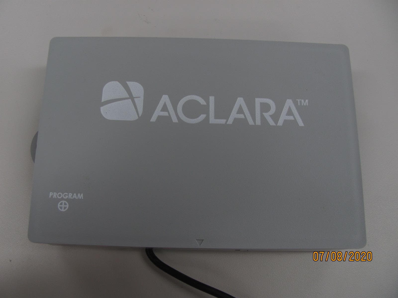
LLB2019006
Aug 04, 2020Water Meter Transponding Unit (MTU)
Equipment Class
TNB - Licensed Non-Broadcast Station Transmitter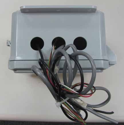
LLB2015001
Dec 10, 2015Series 4000 MTU
Equipment Class
TNB - Licensed Non-Broadcast Station Transmitter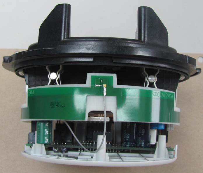
LLBY84000
Sep 28, 2015Synergize RF network utility I210+ meter transponder
Equipment Class
TNB - Licensed Non-Broadcast Station Transmitter