LLM0102WN3501AWireless USB Adapter
Eumitcom Technology Inc.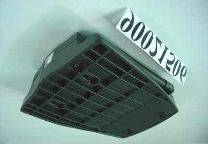
Click to zoom
Application Details
- Equipment Class
- DSS - Part 15 Spread Spectrum Transmitter
- Date of Grant
- Mar 19, 2001
- Application Purpose
- Original Equipment
- Date of Application
- Mar 19, 2001
- Equipment Note
- Wireless USB Adapter
- Frequency Range
- 2412.00000000 - 2462.00000000
- Company
- Eumitcom Technology Inc.
- Country
- Taiwan
Documents & Files
Document Text
Text extracted from the exhibit documents filed with the FCC. Open a document above to read the original.
Users Manual
W W N N 3 3 5 5 0 0 1 1 A A Wireless LAN USB Adapter USER MANUAL Version 1.0 2 Federal Communications Commission Statement This device complies with FCC Rules Part 15. Operation is subject to the following two conditions: This device may not cause harmful interference. This device must accept any interference received, including interference that may cause undesired operation. This equipment has been tested and found to comply with the limits for a Class B digital device, pursuant to Part 15 of the FCC Rules. These limits are designed to provide reasonable protection against harmful interference in a residential installation. This equipment generates, uses and can radiate radio frequency energy. If this equipment is not installed and used in accordance with the manufacturer's instructions, it may cause harmful interference to radio communications. However, there is no guarantee that interference will not occur in a particular installation. If this equipment does cause harmful interference to radio or television reception, which can be determined by during the equipment off and on, the user is encouraged to try to correct the interference by one or more of the following measures: ! Reorient or relocate the receiving antenna. ! Increase the separation between the equipment and receiver. ! Connect the equipment to an outlet on a circuit different from that to which the receiver is connected. ! Consult the dealer or an experienced radio/TV technician for help. The use of shielded cables for connection of the monitor to the graphics card is required to assure compliance with FCC regulations. Changes or modifications to this unit not expressly approved by the party responsible for compliance could void the user's authority to operate this equipment. FCC Radiation Exposure Statement This equipment complies with FCC radiation exposure limits set forth for an uncontrolled environment. This equipment should be installed and operated with minimum distance 20cm between the radiator and your body. Manufacturer's Disclaimer Statement The information in this document is subject to change without notice and does not represent a commitment on the part of the vendor. No warranty or representation, either expressed or implied, is made with respect to the quality, accuracy or fitness for any particular purpose of this document. The manufacturer reserves the right to make changes to the content of this document and/or the products associated with it at any time without obligation to notify any person or organization of such changes. In no event will the manufacturer be liable for direct, indirect, special, incidental or consequential damages arising out of the use or inability to use this product or documentation, even if advised of the possibility of such damages. This document contains materials protected by copyright. All rights are reserved. No part of this manual may be reproduced or transmitted in any form, by any means or for any purpose without expressed written consent of its authors. Product names appearing in this document are mentioned for identification purchases only. All trademarks, product names or brand names appearing in this document are registered property of their respective owners. 3 This device requires a radio license, unless it (including antenna ) is installed totally inside a building. (User must obtain this license from Industry Canada ). “To reduce potential radio interference to other users, the antenna type and its gain should be so chosen that the equivalent isotropically radiated power (EIRP) is not more than that required for successful communication.” Printed in Taiwan 4 Contents Chapter 1 About the WL11000 PCMCIA / PCI Card .................................................. 4 1-1 Features .............................................................................................................................................. 4 1-2 Applications ......................................................................................................................................... 4 1-3 Product Kit ........................................................................................................................................... 5 Chapter 2 Network Configuration and Planning ...................................................... 6 2-1 Network Topology................................................................................................................................ 6 2-2 Roaming .............................................................................................................................................. 8 Chapter 3 Adapter Installation and Configuration – Windows ® 98 / NT / 2000....... 9 3-1 System Requirements ......................................................................................................................... 9 3-2 Inserting the Adapter ........................................................................................................................... 9 3-3.1 WL11000 Driver Installation -Windows ® 98 .................................................................................... 10 3-3.2 Adapter Configuration - Windows ® 98 ............................................................................................ 13 3-3.3 Protocol Installation - Windows ® 98 ................................................................................................ 19 3-4 WL11000 Setup for Windows ® NT 4.0............................................................................................... 24 3-5 WL11000 Setup for Windows ® 2000.................................................................................................. 28 Chapter 4 Installing and Navigating the PRISM Configuration Utility .................. 31 4-1 PRISM Configuration Utility - Installation........................................................................................... 31 4-2 PRISM Configuration Utility- Navigation ....…
Text truncated - open the document above for the full version.
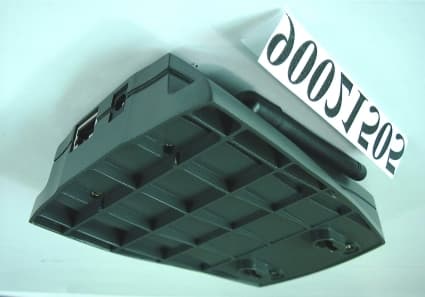
External Photos
Report No.: RF900215061Issued: February 23, 2001 ANNEX 3 PHOTOGRAPHS OF EUT Report No.: RF900215062Issued: February 23, 2001 Report No.: RF900215063Issued: February 23, 2001 Report No.: RF900215069Issued: February 23, 2001 Report No.: RF9002150610Issued: February 23, 2001
ID Label/Location Info
WN3501A FCC ID label: 1. The FCC ID label will paste in the bottom side of the product.( See figure below) MODEL : WN3501A FCC ID: LLM0102WN3501A Canada ID: XXXXXXXXXXXXXX THIS DEVICE COMPLIES WITH PART 15 OF THE FCC RULES.OPERATIONS IS SUBJECT TO THE FOLLOWING TWO CONDITIONS (1) THIS DEVICE MAY NOT CAUSE HARMFUL INTERFERENCE AND(2) THIS DEVICE MUST ACCEPT ANY INTERFERENCE THAT MAY CAUSE UNDESIRED OPERATION. Complies with CANADA RSS-210" Eumitcom Technology Inc. Made in Taiwan 4 CM BOTTOM SIDE 6 CM
Internal Photos
Report No.: RF900215064Issued: February 23, 2001 Report No.: RF900215065Issued: February 23, 2001 Report No.: RF900215066Issued: February 23, 2001 Report No.: RF900215067Issued: February 23, 2001 Report No.: RF900215068Issued: February 23, 2001
Test Report
FCC ID: LLM0102WN3501A Report No.: RF90021506 1 Issued: Feb. 23, 2001 FCC TEST REPORT REPORT NO.: RF90021506 MODEL NO.: WN3501A RECEIVED: February 15, 2001 TESTED: February 21, 2001 APPLICANT: Eumitcom Technology Inc. ADDRESS: 2F, No.2, Li Hsin Rd., Science-Based Industrial Park, Hsinchu, Taiwan, R.O.C. ISSUED BY: Advance Data Technology Corporation LAB LOCATION: 13-1, Lane 19, Wen Shan 3 rd St., Kweishan, Taoyuan Hsien, Taiwan, R.O.C. This test report consists of 48 pages in total. It may be duplicated completely for legal use with the approval of the applicant. It should not be reproduced except in full, without the written approval of our laboratory. The client should not use it to claim product endorsement by NVLAP or any U.S. government agencies. The test results in the report only apply to the tested sample. Accredited Laboratory FCC ID: LLM0102WN3501A Report No.: RF90021506 2 Issued: Feb. 23, 2001 Table of Contents 1CERTIFICATION ...................................................................................................... 4 2SUMMARY OF TEST RESULTS............................................................................. 5 3GENERAL INFORMATION .................................................................................... 6 3.1GENERAL DESCRIPTION OF EUT .......................................................................................6 3.2DESCRIPTION OF TEST MODES ..........................................................................................6 3.3GENERAL DESCRIPTION OF APPLIED STANDARDS ......................................................7 3.4DESCRIPTION OF SUPPORT UNITS ....................................................................................7 4TEST PROCEDURES AND RESULTS ................................................................... 8 4.1CONDUCTED EMISSION MEASUREMENT........................................................................8 4.1.1LIMITS OF CONDUCTED EMISSION MEASUREMENT ..................................................................8 4.1.2TEST INSTRUMENTS ...........................................................................................................................8 4.1.3TEST PROCEDURES .............................................................................................................................9 4.1.4TEST SETUP .........................................................................................................................................10 4.1.5TEST RESULTS ....................................................................................................................................11 4.2RADIATED EMISSION MEASUREMENT ..........................................................................17 4.2.1LIMITS OF RADIATED EMISSION MEASUREMENT.....................................................................17 4.2.2TEST INSTRUMENTS .........................................................................................................................18 4.2.3TEST PROCEDURES ...........................................................................................................................19 4.2.4TEST SETUP .........................................................................................................................................20 4.2.5TEST RESULTS ....................................................................................................................................21 4.36DB BANDWIDTH MEASUREMENT .................................................................................25 4.3.1LIMITS OF 6 D B BANDWIDTH MEASUREMENT............................................................................25 4.3.2TEST INSTRUMENTS .........................................................................................................................25 4.3.3TEST PROCEDURE..............................................................................................................................26 4.3.4TEST SETUP .........................................................................................................................................26 4.3.5EUT OPERATING CONDITION..........................................................................................................26 4.3.6TEST RESULTS ....................................................................................................................................27 4.4MAXIMUM PEAK OUTPUT POWER..................................................................................31 4.4.1LIMITS OF MAXIMUM PEAK OUTPUT POWER MEASUREMENT.............................................31 4.4.2INSTRUMENTS....................................................................................................................................31 4.4.3TEST PROCEDURES ...........................................................................................................................32 4.4.4TEST SETUP .........................................................................................................................................32 4.4.5EUT OPERATING CONDITION..........................................................................................................32 4.4.6TEST RESULTS ....................................................................................................................................33 4.5POWER SPECTRAL DENSITY MEASUREMENT .............................................................34 4.5.1LIMITS OF POWER SPECTRAL DENSITY MEASUREMENT .......................................................34 4.5.2TEST INSTRUMENTS .........................................................................................................................34 FCC ID: LLM0102WN3501A Report No.: RF90021506 3 Issued: Feb. 23, 2001 4.5.3TEST PROCEDURE..............................................................................................................................35 4.5.4TEST SETUP .…
Text truncated - open the document above for the full version.
Test Report
FCC ID: LLM0102WN3501A Report No.: RF90021506 31 Issued: Feb. 23, 2001 4.4 MAXIMUM PEAK OUTPUT POWER 4.4.1 LIMITS OF MAXIMUM PEAK OUTPUT POWER MEASUREMENT The Limit of Maximum Peak Output Power Measurement is 30dBm. 4.4.2 INSTRUMENTS Description & ManufacturerModel No.Serial No.Calibrated Until HP SPECTRUM ANALYZER8593E3926A04191Mar. 03, 2001 HP ATTENUATOR8496B3247A18505Cal. on use HP PLOTTER7475A2641V27755N/A Notes: 1.The measurement uncertainty is less than +/- 2.6dB, which is calculated as per the NAMAS document NIS81. 2.The calibration interval of the above test instruments is 12 months. And the calibrations are traceable to NML/ROC and NIST/USA. FCC ID: LLM0102WN3501A Report No.: RF90021506 32 Issued: Feb. 23, 2001 4.4.3 TEST PROCEDURES 1. The transmitter output was connected to the spectrum analyzer through an attenuator. 2. The center frequency of the spectrum analyzer is set to the fundamental frequency and using 3 MHz RBW and 3 MHz VBW. 3. The span of the spectrum analyzer should be larger than 6dB BandWidth plus 10MHz. 4. Use Peak Search to read the peak power after Maximum Hold function is activated. 5. Shift the marker to +/- 3MHz and +/-6MHz, and record the reading. 6. The Maximum Peak Output Power is the linear summation of the 5 readings in (4) and (5). Note: This measurement is the total power of 15MHz bandwidth which is far more wider than 6dB bandwidth. 4.4.4 TEST SETUP For the actual test configuration, please refer to the related Item – Photographs of the Test Configuration. 4.4.5 EUT OPERATING CONDITION The software provided by client enabled the EUT to transmit and receive data at lowest, middle and highest channel frequencies individually. EUT SPECTRUM ANALYZER Attenuator FCC ID: LLM0102WN3501A Report No.: RF90021506 33 Issued: Feb. 23, 2001 4.4.6 TEST RESULTS Output Power Into Antenna: EUTWireless USB AdapterModelWN3501A Environmental Conditions 20°C, 70%RHTe s t e d B ySteven Lu CHANNEL CHANNEL FREQUENCY (MHz) PEAK POWER OUTPUT (dBm) PEAK POWER LIMIT (dBm) PASS/FAI L 1241217.6730PASS 6243717.4130PASS 11246217.6430PASS FCC ID: LLM0102WN3501A Report No.: RF90021506 34 Issued: Feb. 23, 2001 4.5 POWER SPECTRAL DENSITY MEASUREMENT 4.5.1 LIMITS OF POWER SPECTRAL DENSITY MEASUREMENT The Limit of Power Spectral Density Measurement is 8dBm. 4.5.2 TEST INSTRUMENTS Description & ManufacturerModel No.Serial No.Calibrated Until ROHDE & SCHWARZ TEST RECEIVER ESMI 846839/018 848926/005 Mar. 03, 2001 HP ATTENUATOR8496B3247A18505Cal. on use HP PLOTTER7475A2641V27755N/A Notes: 1.The measurement uncertainty is less than +/- 2.6dB, which is calculated as per the NAMAS document NIS81. 2.The calibration interval of the above test instruments is 12 months. And the calibrations are traceable to NML/ROC and NIST/USA. FCC ID: LLM0102WN3501A Report No.: RF90021506 35 Issued: Feb. 23, 2001 4.5.3 TEST PROCEDURE The transmitter output was connected to the spectrum analyzer through an attenuator, the bandwidth of the fundamental frequency was measured with the spectrum analyzer using 3 kHz RBW and 30 kHz VBW, set sweep time=span/3kHz. The power spectral density was measured and recorded. The sweep time is allowed to be longer than span/3KHz for a full response of the mixer in the spectrum analyzer. 4.5.4 TEST SETUP For the actual test configuration, please refer to the related Item – Photographs of the Test Configuration. 4.5.5 EUT OPERATING CONDITION The software provided by client enabled the EUT to transmit and receive data at lowest, middle and highest channel frequencies individually. EUT SPECTRUM ANALYZER Attenuator FCC ID: LLM0102WN3501A Report No.: RF90021506 36 Issued: Feb. 23, 2001 4.5.6 TEST RESULTS EUTWireless USB AdapterModelWN3501A Environmental Conditions 20°C, 70%RHTe s t e d B ySteven Lu CHANNEL NUMBER CHANNEL FREQUENCY (MHz ) RF POWER LEVEL IN 3 KHz BW (dBm) MAXIMUM LIMIT (dBm) PASS/FAI L 12412-11.128PASS 62437-12.548PASS 112462-9.378PASS FCC ID: LLM0102WN3501A Report No.: RF90021506 37 Issued: Feb. 23, 2001 CH1 FCC ID: LLM0102WN3501A Report No.: RF90021506 38 Issued: Feb. 23, 2001 CH6 FCC ID: LLM0102WN3501A Report No.: RF90021506 39 Issued: Feb. 23, 2001 CH11 FCC ID: LLM0102WN3501A Report No.: RF90021506 40 Issued: Feb. 23, 2001 4.6 BAND EDGES MEASUREMENT 4.6.1 LIMITS OF BAND EDGES MEASUREMENT Below –20dB of the highest emission level of operating band (in 100KHz RB). 4.6.2 TEST INSTRUMENTS Description & ManufacturerModel No.Serial No.Calibrated Until ROHDE & SCHWARZ TEST RECEIVER ESMI 848926/005 846839/018 Dec 03, 2001 HP ATTENUATOR8496B3247A18505Cal. on use HP PLOTTER7475A2641V27755N/A Notes: 1.The measurement uncertainty is less than +/- 2.6dB, which is calculated as per the NAMAS document NIS81. 2.The calibration interval of the above test instruments is 12 months. And the calibrations are traceable to NML/ROC and NIST/USA. 4.6.3 TEST PROCEDURE The transmitter output was connected to the spectrum analyzer via a low lose cable. Set both RBW and VBW of spectrum analyzer to 100 kHz with suitable frequency span including 100 kHz bandwidth from band edge. The band edges was measured and recorded. FCC ID: LLM0102WN3501A Report No.: RF90021506 41 Issued: Feb. 23, 2001 4.6.4 EUT OPERATING CONDITION The software provided by client enabled the EUT to transmit and receive data at lowest, middle and highest channel frequencies individually. 4.6.5 TEST RESULTS The spectrum plots are attached below. D2 line indicates the highest level, D1 line indicates the 20dB offset below D2. It shows compliance with the requirement in part 15.247(C). FCC ID: LLM0102WN3501A Report No.: RF90021506 42 Issued: Feb. 23, 2001 4.6.6 NOTE ON BAND EDGE EMISSION The band edge emission plot on page 43 shows 44.57dB delta between carrier maximum power and local maximum emission in restrict band (2.4835GHz). The emission of carrier strength list in table of page 24 is 97.1dBμV/m, so the maximum field strength in restrict band is 97.1- 44.57= 52.53dBμV/m which is under 54 dBμV/m limit. FCC ID: LLM0102WN3501A Re…
Text truncated - open the document above for the full version.
Test Setup Photos
FCC ID: LLM0102WN3501A Report No.: RF90021506 46 Issued: Feb. 23, 2001 5 PHOTOGRAPHS OF THE TEST CONFIGURATION CONDUCTED EMISSION TEST FCC ID: LLM0102WN3501A Report No.: RF90021506 47 Issued: Feb. 23, 2001 RADIATED EMISSION TEST
Contact Information
Applicant
Roger Wu(Vice President)
886 3 578-5717Fax: 886 3 578-5817
Test Firm
Bureau Veritas CPS (H.K.) Ltd. Taoyuan BranchTommy Wu
Technical Specifications
| # | Rule Parts | Frequency Range | Power Output |
|---|---|---|---|
| 1 | 15C | 2.41 GHz - 2.46 GHz | 58.00 mW |
Other Applications from Eumitcom Technology Inc.
LLM0102WA3001A
Mar 19, 200111Mbps WLAN Access Point
Equipment Class
DSS - Part 15 Spread Spectrum Transmitter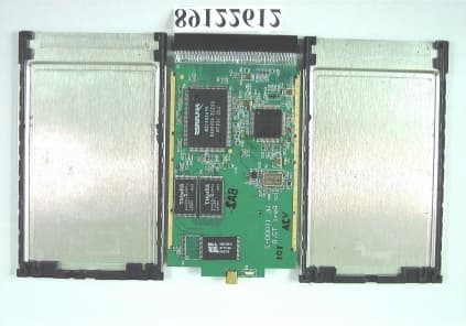
LLM101WL11000-2-E
Feb 13, 2001Wireless PCMCIA LAN Card
Equipment Class
DSS - Part 15 Spread Spectrum Transmitter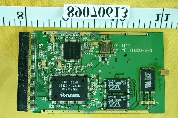
LLM007WL11000-2
Oct 30, 2000Wireless LAN Card
Equipment Class
DSS - Part 15 Spread Spectrum Transmitter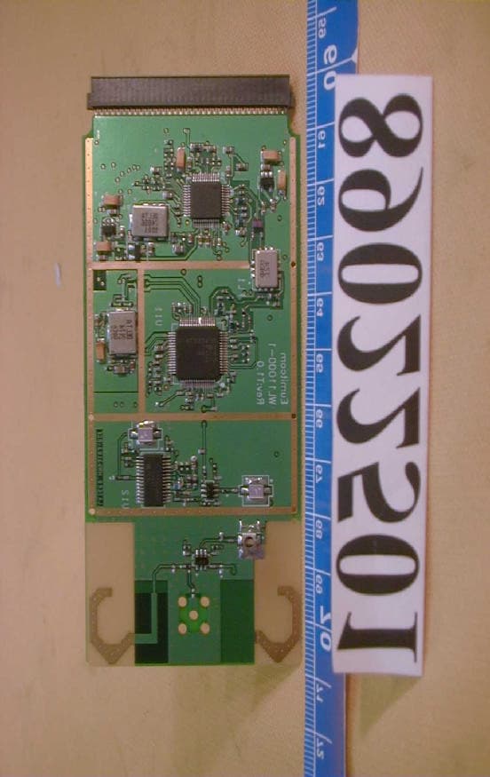
LLM002WL11000-1
May 18, 2000PCMCIA Card
Equipment Class
DSS - Part 15 Spread Spectrum Transmitter
LLM9908WL1000
Jan 11, 2000JBP - Part 15 Class B Computing Device Peripheral
Equipment Class
JBP - Part 15 Class B Computing Device Peripheral