LPR418M1RTR-4 Wireless Option
Leidos, Inc.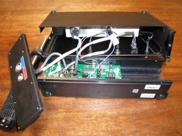
Click to zoom
Application Details
- Equipment Class
- DSC - Part 15 Security/Remote Control Transmitter
- Date of Grant
- Jul 11, 2002
- Application Purpose
- Original Equipment
- Date of Application
- Jul 11, 2002
- Equipment Note
- RTR-4 Wireless Option
- Frequency Range
- 418.00000000 - 418.00000000
- Company
- Leidos, Inc.
- Country
- United States
Documents & Files
Document Text
Text extracted from the exhibit documents filed with the FCC. Open a document above to read the original.
Users Manual
1999 Microchip Technology Inc.PreliminaryDS21137E-page 1 FEATURES Security • Programmable 28-bit serial number • Programmable 64-bit encryption key • Each transmission is unique • 66-bit transmission code length • 32-bit hopping code • 34-bit fixed code (28-bit serial number, 4-bit button code, 2-bit status) • Encryption keys are read protected Operating • 2.0—6.3V operation • Four button inputs • No additional circuitry required • 15 functions available • Selectable baud rate • Automatic code word completion • Battery low signal transmitted to receiver • Non-volatile synchronization data Other • Easy to use programming interface • On-chip EEPROM • On-chip oscillator and timing components • Button inputs have internal pulldown resistors • Current limiting on LED output • Minimum component count • Synchronous transmission mode Typical Applications The HCS300 is ideal for Remote Keyless Entry (RKE) applications. These applications include: • Automotive RKE systems • Automotive alarm systems • Automotive immobilizers • Gate and garage door openers • Identity tokens • Burglar alarm systems DESCRIPTION The HCS300 from Microchip Technology Inc., is a code hopping encoder designed for secure Remote Keyless Entry (RKE) systems. The HCS300 utilizes the ® code hopping technology, which incorporates high security, a small package outline and low cost to make this device a perfect solution for unidirectional remote keyless entry systems and access control systems. PACKAGE TYPES HCS300 BLOCK DIAGRAM 1 2 3 4 8 7 6 5 S0 S1 S2 S3 VDD LED PWM V SS PDIP, SOIC HCS300 VSS VDD Oscillator Reset circuit LED driver Controller Power latching and switching Button input port 32-bit shift register Encoder EEPROM PWM LED S 3 S 2 S 1 S 0 KEELOQ ® Code Hopping Encoder HCS300 KEELOQ is a registered trademark of Microchip Technology, Inc. Microchip’s Secure Data Products are covered by some or all of the following patents: Code hopping encoder patents issued in Europe, U.S.A., and R.S.A. — U.S.A.: 5,517,187; Europe: 0459781; R.S.A.: ZA93/4726 21137e.Book Page 1 Monday, October 4, 1999 8:04 AM HCS300 DS21137E-page 2Preliminary 1999 Microchip Technology Inc. The HCS300 combines a 32-bit hopping code generated by a non-linear encryption algorithm, with a 28-bit serial number and six status bits to create a 66- bit transmission stream. The length of the transmission eliminates the threat of code scanning and the code hopping mechanism makes each transmission unique, thus rendering code capture and resend (code grab- bing) schemes useless. The encryption key, serial number, and configuration data are stored in EEPROM, which is not accessible via any external connection. This makes the HCS300 a very secure unit. The HCS300 provides an easy to use serial interface for programming the necessary security keys, system parameters, and configuration data. The encyrption keys and code combinations are pro- grammable but read-protected. The keys can only be verified after an automatic erase and programming operation. This protects against attempts to gain access to keys and manipulate synchronization values. The HCS300 operates over a wide voltage range of 2.0V to 6.3V and has four button inputs in an 8-pin configuration. This allows the system designer the freedom to utilize up to 15 functions. The only components required for device operation are the but- tons and RF circuitry, allowing for a very low system cost. 1.0SYSTEM OVERVIEW Key Terms • Manufacturer’s code - a 64-bit word, unique to each manufacturer, used to produce a unique encryption key in each transmitter (encoder). • Encryption Key - a unique 64-bit key generated and programmed into the encoder during the manufacturing process. The encryption key controls the encryption algorithm and is stored in EEPROM on the encoder device. 1.1Learn The HCS product family facilitates several learn strate- gies to be implemented on the decoder. The following are examples of what can be done. It must be pointed out that there exists some third-party patents on learn- ing strategies and implementation. 1.1.1NORMAL LEARN The receiver uses the same information that is trans- mitted during normal operation to derive the transmit- ter’s secret key, decrypt the discrimination value and the synchronization counter. 1.1.2SECURE LEARN* The transmitter is activated through a special button combination to transmit a stored 48-bit value (random seed) that can be used for key generation or be part of the key. Transmission of the random seed can be dis- abled after learning is completed. The HCS300 is a code hopping encoder device that is designed specifically for keyless entry systems, primarily for vehicles and home garage door openers. It is meant to be a cost-effective, yet secure solution to such systems. The encoder portion of a keyless entry system is meant to be held by the user and operated to gain access to a vehicle or restricted area. The HCS300 requires very few external components (Figure 2-1). Most keyless entry systems transmit the same code from a transmitter every time a button is pushed. The relative number of code combinations for a low end system is also a relatively small number. These shortcomings provide the means for a sophisticated thief to create a device that ‘grabs’ a transmission and re-transmits it later or a device that scans all possible combinations until the correct one is found. The HCS300 employs the code hopping technology and an encryption algorithm to achieve a high level of security. Code hopping is a method by which the code transmitted from the transmitter to the receiver is different every time a button is pushed. This method, coupled with a transmission length of 66 bits, virtually eliminates the use of code ‘grabbing’ or code ‘scanning’. As indicated in the block diagram on page one, the HCS300 has a small EEPROM array which must be loaded with several parameters before use. The most important of these values are: • A 28-bit serial number which is me…
Text truncated - open the document above for the full version.
Users Manual
2001 Microchip Technology Inc. DS30292C PIC16F87X Data Sheet 28/40-Pin 8-Bit CMOS FLASH Microcontrollers DS30292C - page ii 2001 Microchip Technology Inc. “All rights reserved. Copyright © 2001, Microchip Technology Incorporated, USA. Information contained in this publication regarding device applications and the like is intended through suggestion only and may be superseded by updates. No rep- resentation or warranty is given and no liability is assumed by Microchip Technology Incorporated with respect to the accu- racy or use of such information, or infringement of patents or other intellectual property rights arising from such use or oth- erwise. Use of Microchip’s products as critical components in life support systems is not authorized except with express written approval by Microchip. No licenses are conveyed, implicitly or otherwise, under any intellectual property rights. The Microchip logo and name are registered trademarks of Microchip Technology Inc. in the U.S.A. and other countries. All rights reserved. All other trademarks mentioned herein are the property of their respective companies. No licenses are conveyed, implicitly or otherwise, under any intellectual prop- erty rights.” Trademarks The Microchip name, logo, PIC, PICmicro, PICMASTER, PIC- START, PRO MATE, K EELOQ, SEEVAL, MPLAB and The Embedded Control Solutions Company are registered trade- marks of Microchip Technology Incorporated in the U.S.A. and other countries. Total Endurance, ICSP, In-Circuit Serial Programming, Filter- Lab, MXDEV, microID, FlexROM, fuzzyLAB, MPASM, MPLINK, MPLIB, PICDEM, ICEPIC, Migratable Memory, FanSense, ECONOMONITOR and SelectMode are trade- marks of Microchip Technology Incorporated in the U.S.A. Serialized Quick Term Programming (SQTP) is a service mark of Microchip Technology Incorporated in the U.S.A. All other trademarks mentioned herein are property of their respective companies. © 2001, Microchip Technology Incorporated, Printed in the U.S.A., All Rights Reserved. Microchip received QS-9000 quality system certification for its worldwide headquarters, design and wafer fabrication facilities in Chandler and Tempe, Arizona in July 1999. The Company’s quality system processes and procedures are QS-9000 compliant for its PICmicro ® 8-bit MCUs, KEELOQ ® code hopping devices, Serial EEPROMs and microperipheral products. In addition, Microchip’s quality system for the design and manufacture of development systems is ISO 9001 certified. 2001 Microchip Technology Inc.DS30292C-page 1 PIC16F87X Devices Included in this Data Sheet: Microcontroller Core Features: •High performance RISC CPU •Only 35 single word instructions to learn •All single cycle instructions except for program branches which are two cycle •Operating speed: DC - 20 MHz clock input DC - 200 ns instruction cycle •Up to 8K x 14 words of FLASH Program Memory, Up to 368 x 8 bytes of Data Memory (RAM) Up to 256 x 8 bytes of EEPROM Data Memory •Pinout compatible to the PIC16C73B/74B/76/77 •Interrupt capability (up to 14 sources) •Eight level deep hardware stack •Direct, indirect and relative addressing modes •Power-on Reset (POR) •Power-up Timer (PWRT) and Oscillator Start-up Timer (OST) •Watchdog Timer (WDT) with its own on-chip RC oscillator for reliable operation •Programmable code protection •Power saving SLEEP mode •Selectable oscillator options •Low power, high speed CMOS FLASH/EEPROM technology •Fully static design •In-Circuit Serial Programming (ICSP) via two pins •Single 5V In-Circuit Serial Programming capability •In-Circuit Debugging via two pins •Processor read/write access to program memory •Wide operating voltage range: 2.0V to 5.5V •High Sink/Source Current: 25 mA •Commercial, Industrial and Extended temperature ranges •Low-power consumption: - < 0.6 mA typical @ 3V, 4 MHz -20 μA typical @ 3V, 32 kHz -< 1 μA typical standby current Pin Diagram Peripheral Features: •Timer0: 8-bit timer/counter with 8-bit prescaler •Timer1: 16-bit timer/counter with prescaler, can be incremented during SLEEP via external crystal/clock •Timer2: 8-bit timer/counter with 8-bit period register, prescaler and postscaler •Two Capture, Compare, PWM modules - Capture is 16-bit, max. resolution is 12.5 ns - Compare is 16-bit, max. resolution is 200 ns - PWM max. resolution is 10-bit •10-bit multi-channel Analog-to-Digital converter •Synchronous Serial Port (SSP) with SPI (Master mode) and I 2 C (Master/Slave) •Universal Synchronous Asynchronous Receiver Transmitter (USART/SCI) with 9-bit address detection •Parallel Slave Port (PSP) 8-bits wide, with external RD , WR and CS controls (40/44-pin only) •Brown-out detection circuitry for Brown-out Reset (BOR) •PIC16F873 •PIC16F874 •PIC16F876 •PIC16F877 RB7/PGD RB6/PGC RB5 RB4 RB3/PGM RB2 RB1 RB0/INT VDD VSS RD7/PSP7 RD6/PSP6 RD5/PSP5 RD4/PSP4 RC7/RX/DT RC6/TX/CK RC5/SDO RC4/SDI/SDA RD3/PSP3 RD2/PSP2 MCLR/VPP RA0/AN0 RA1/AN1 RA2/AN2/VREF- RA3/AN3/VREF+ RA4/T0CKI RA5/AN4/SS RE0/RD/AN5 RE1/WR/AN6 RE2/CS/AN7 VDD VSS OSC1/CLKIN OSC2/CLKOUT RC0/T1OSO/T1CKI RC1/T1OSI/CCP2 RC2/CCP1 RC3/SCK/SCL RD0/PSP0 RD1/PSP1 1 2 3 4 5 6 7 8 9 10 11 12 13 14 15 16 17 18 19 20 40 39 38 37 36 35 34 33 32 31 30 29 28 27 26 25 24 23 22 21 PIC16F877/874 PDIP 28/40-Pin 8-Bit CMOS FLASH Microcontrollers PIC16F87X DS30292C-page 2 2001 Microchip Technology Inc. Pin Diagrams PIC16F876/873 10 11 2 3 4 5 6 1 8 7 9 12 13 14 15 16 17 18 19 20 23 24 25 26 27 28 22 21 MCLR/VPP RA0/AN0 RA1/AN1 RA2/AN2/V REF- RA3/AN3/V REF+ RA4/T0CKI RA5/AN4/SS VSS OSC1/CLKIN OSC2/CLKOUT RC0/T1OSO/T1CKI RC1/T1OSI/CCP2 RC2/CCP1 RC3/SCK/SCL RB7/PGD RB6/PGC RB5 RB4 RB3/PGM RB2 RB1 RB0/INT V DD VSS RC7/RX/DT RC6/TX/CK RC5/SDO RC4/SDI/SDA 10 11 12 13 14 15 16 17 181920212223242526 44 8 7 654321 2728 29 30 31 32 33 34 35 36 37 38 39 40414243 9 PIC16F877 RA4/T0CKI RA5/AN4/SS RE0/RD/AN5 OSC1/CLKIN OSC2/CLKOUT RC0/T1OSO/T1CK1 NC RE1/WR /AN6 RE2/CS /AN7 V DD VSS RB3/PGM RB2 RB1 RB0/INT V DD VSS RD7/PSP7 RD6/PSP6 RD5/PSP5 RD4/PSP4 RC7/RX/DT RA3/AN3/V REF …
Text truncated - open the document above for the full version.
Users Manual
RTR-4 RTR-4 Portable Digital X-Ray Imaging System Operator’s Manual Supplement Wireless Option Document 306847 Revision A SAIC 16701 W. Bernardo Dr. San Diego, CA 92127-1903 U.S.A. Copyright © 2001 SAIC All rights reserved. Printed in the United States of America. All data and information contained in or disclosed by this document are confidential and proprietary information of SAIC and its affiliates and all rights therein are expressly reserved. By accepting this material, the recipient agrees that this material and the information contained herein are held in confidence and in trust and will not be used, copied, or reproduced in whole or in part, nor its contents revealed in any manner to others without the express written permission of SAIC. The recipient also agrees not to allow the use of this document by others without the express written consent of SAIC. This technology is controlled by the U.S. Government. Diversion contrary to U.S. law prohibited. SAIC reserves the right to change or revise this information without notice. Reasonable effort has been made to ensure that the information in this manual is accurate; however, SAIC assumes no responsibility for inaccuracies or omissions of any kind. SAIC makes no warranty for the use of its product. SAIC is a registered trademark of Science Applications International Corporation. RTR-4™ is a trademark of SAIC. RTR-4 Portable Digital X-Ray Imaging System Operator’s Manual Supplement, Wireless Option Document 306847 Rev A FCC Compliance Statement FEDERAL COMMUNICATIONS COMMISSION RADIO AND TELEVISION INTERFERENCE STATEMENT FOR A CLASS ’B’ DEVICE This equipment has been tested and found to comply with the limits for a Class B digital device, pursuant to Part 15 of the FCC Rules. These limits are designed to provide reasonable protection against harmful interference in a residential installation. This equipment generates, uses and can radiate radio frequency energy and, if not installed and used in accordance with the instructions, may cause harmful interference to radio communications. However, there is no guarantee that interference will not occur in a particular installation. If this equipment does cause interference to radio or television reception, which can be determined by turning the equipment off and then on, the user is encouraged to try to correct the interference by one of more of the following measures: •Reorient or relocate the receiving antenna. •Increase the separation between the equipment and receiver •Connect the equipment into a different outlet so that the equipment and receiver are on different branch circuits. •Consult the dealer or an experienced radio/TV technician for help. This device complies with Part 15, of the FCC Rules. Operation is subject to the following two conditions: (1) this device may not cause harmful interference, and (2) this device must accept any interference received including interference that may cause undesired operation. Changes or modifications not expressly approved by Science Applications International Corporation could void the user’s authority to operate the equipment. FCC RF Exposure Statement This device complies with FCC radiation exposure limits as set forth for an uncontrolled environment. This device should be installed and operated with a minimum separation distance of 20 cm between the radiator and your body. 306847 Rev ASAIC Proprietary Revision History VersionRelease DateNotes --2001 Sept. 21Original release A2002 July 12FCC statements Revision HistoryRTR-4 Portable Digital X-Ray Imaging System - Operator’s Manual Supplement Original ReleaseSAIC Proprietary 306847 Rev ASAIC Proprietary1-1 1 Introduction About This Manual The RTR-4 Wireless Operator’s Manual is comprised of the following chapters: • Chapter 1 - Introduction • Chapter 2 - Safety Summary • Chapter 3 - Wireless Option Description • Chapter 4 - Wireless Option Setup •Chapter 5 - Wireless Option Operation • Chapter 6 - Wireless Option Maintenance & Troubleshooting Purpose and Scope This manual describes and provides instructions for the setup, operation and troubleshooting of RTR-4 Wireless Option in conjunction only with the RTR-4 Portable Digital X-Ray Imaging System and the Golden Engineering XR200 X-Ray Source. It is to be used only by technicians and operators authorized to operate the RTR-4 Portable Digital X-Ray Imaging System. The RTR-4 Wireless Option is not supplied as standard equipment with the RTR-4 Portable Digital X-Ray Imaging System and must be ordered separately. RTR-4 Technical Support On-call RTR-4 technical support at SAIC is available from 7:30 AM to 4:00 PM, (0730-1600) Monday through Friday, Pacific Time. Support can be reached by the following means: •Call (800) 962-1632 (North America only). •Call (858) 826-9831 (outside of North America) RTR-4 technical support questions can also be submitted at any time by the following means: •Fax: (858) 826-9009 •E-mail: [email protected] RTR-4 Portable Digital X-Ray Imaging System-Operator’s Manual Supplement 1-2SAIC Proprietary306847 Rev A Document Revisions This manual supplements the RTR-4 Operator’s Manual (SAIC Document 120300, Rev C.) When changes to this or the main operator’s manual are required, new manuals incorporating the changes are released as appropriate . Acronyms and Abbreviations The table below lists and defines some of the acroynms and abbreviations used in this manual. Table 1-1: Acronyms and Abbreviations TA TermDefinition CU-4Control Unit 4 (the original controller.) ESDElectrostatic discharge GHzGigahertz HFHigh Frequency LEDLight Emitting Diode MBMegabyte NCUNotebook Control Unit NICNetwork Interface Card PCMCIAPersonal Computer Memory Card International Association SAIC ™ Science Applications International Corporation RFRadio Frequency 306847 Rev ASAIC Proprietary2-1 2 Safety Summary Introduction Observe the following safety precautions when installing, assembling/disassembling, transporting, storing, operating, tes…
Text truncated - open the document above for the full version.
Users Manual
RTR-4 Portable Digital X-Ray Imaging System--Operator’s Manual Supplement 3-2SAIC Proprietary306847 Rev A Figure 3-1: RTR-4 Wireless Option Items Figure 3-2: Power/Transceiver Unit 1 2 3 4 5 67 8 9 RTR-4 Portable Digital X-Ray Imaging System--Operator’s Manual Supplement 306847 Rev ASAIC Proprietary3-3 The Power/Transceiver unit (Figure 3-2) has three functions: •Provides power to the imager previously supplied by the controller (in the CU-4 case) or the external power supply (in the notebook case). •Facilitates wireless communication between the controller and the imager. •Sends the wireless signal from the imager to the x-ray source for firing x-rays. The Power/Transceiver unit has five assemblies: •The black chassis •Antenna 1 (tall, transceiving antenna) •Antenna 2 (short, transmitting antenna) •The blue Power/Transceiver-to-Imager cable for controller-and-imager communications •The gray Power/Transceiver-to-Imager cable for imager-to-x-ray-source communications The chassis houses all the active components, the battery, the imager-to-controller transceiver, and the x-ray transmitter. Antenna 1 provides signals for communication with the controller; Antenna 2 provides signals to the X-ray Receiver. The blue cable provides communication to the imager, and the gray cable (with one red strain relief and one yellow) provides communication from the imager for x-ray firing purposes. The Power/Transceiver has a convenient briefcase-style handle and contains a 10.8-Volt smart battery that is the same type as provided with the CU-4 controllers. This battery can be recharged using either the single-slot or the dual-slot charger sometimes rovided with the RTR-4 controllers, or in the RTR-4 CU-4 controller's battery compartment. The Power/Transceiver also has a power switch and a power-indication LED as shown in Figure 3-2. The battery is in use whenever the power switch is on and the LED is illuminated. (Early versions have a red LED; later versions have a green LED.) Radio-frequency communications between the Imager and the Controller combined with the radio-frequency communications with the X-ray Receiver are very low intensity. When the Power/Transceiver is more than 50 cm (1.5 feet) away from a target device, then the RTR-4 Wireless Option complies with the HERO specifications. (If the RTR-4 is not being used with potentially-explosive devices, then this specification is irrelevant.) RTR-4 Portable Digital X-Ray Imaging System--Operator’s Manual Supplement 3-4SAIC Proprietary306847 Rev A The transmission frequency of the Power/Transceiver when communicating with the imager is near 2.4 GHz. This communication is done between 2.4000 and 2.4835 GHz, is spread-spectrum and frequency-hopping, according to the IEEE-802.11b-1999 standard, and is further encrypted to minimize snooping or spoofing. The frequency used when transmitting to the X-ray Receiver is about 418 MHz, is very low power and is coded with a sequencing 64-bit security code to minimize the possibility of unintended source firing. Battery replacement procedures are described in Chapter 6. X-ray Receiver Unit The X-ray Receiver unit (Figure 3-3) receives a signal from the Power/Transceiver and fires the x-ray source. It has two components, the body and the cable. The detachable cable can accommodate any of the four x-ray sources manufactured by Golden Engineering. They are listed below in order of their appearance from top to bottom in Figure 3-4: • Inspector Model 200 (special cable) • XR-150 (special cable) • XRS-3 (standard cable) • XR-200 (standard cable) The Inspector Model 200 was discontinued by Golden Engineering in 1998, but the RTR-4 Wireless Option still supports it. The X-ray Receiver unit is powered by a standard 9-volt alkaline battery and has a power switch with an indicating LED. Battery replacement procedures are described in Chapter 6. Figure 3-3: X-Ray Receiver Unit RTR-4 Portable Digital X-Ray Imaging System--Operator’s Manual Supplement 306847 Rev ASAIC Proprietary3-5 Figure 3-4: Four Golden Engineering X-ray Source Units RTR-4 Portable Digital X-Ray Imaging System--Operator’s Manual Supplement 3-6SAIC Proprietary306847 Rev A 306847 Rev ASAIC Proprietary4-1 4 Wireless Option Setup Introduction This chapter describes the tasks uniquely required to prepare the RTR-4 Wireless Option for operation to be described in Chapter 5. Routine RTR-4 physical setup procedures are described in Chapter 2 of the RTR-4 Operator’s Manual except for the Wireless Option Setup tasks described here. The wireless option setup tasks in their proper sequence are: • Power Transceiver Setup • X-ray Receiver Setup • WiFi NIC Setup • Optional Medium-Range Antenna Setup • System Initialization • Wireless Connection Test Power/Transceiver Setup Connecting the Power/Transceiver Connecting the Power/Transceiver Description The Power Transceiver must be connected to the XR200 X-Ray source and Imager order for the XR200 and Imager to transceive commands with the controller. Prerequisites None. Connecting the Power/Transceiver The Power Transceiver is connected to the XR200 and Imager as follows STEP ACTION 1 Remove the Power Transceiver (Figure 3-2) from its packing case and place it on a flat, solid surface as close as possible to the XR200 and Imager. RTR-4 Portable Digital X-Ray Imaging System--Operator’s Manual Supplement 4-2 SAIC Proprietary306847 Rev A 2 Screw on the two antennas (one shorter, one taller) to the Power/Transceiver as shown below: 3 Insert one end of the Power/Transceiver’s “X-Ray” coaxial cable into the red-labeled “X-Ray” jack on the right-hand end of the Power Transceiver as shown below. STEP ACTION
Users Manual
RTR-4 Portable Digital X-Ray Imaging System--Operator’s Manual Supplement 306847 Rev ASAIC Proprietary4-3 3 Insert one end of the Power/Transceiver’s “Imager” coaxial cable into the blue labeled “Imager” jack on the right-hand end of the Power/Transceiver and the other to the appropriate jack on the Imager. 4 Power up the Power/Transceiver by pressing its On/Off rocker switch to the On position as shown below. The red “POWER” LED to the right of the switch should illuminate. NOTE If the “POWER” LED fails to illuminate, replace the Power/ Transceiver battery in accordance with the procedure in Chapter 6. If it still fails to illuminate, replace the Power/Transceiver. STEP ACTION RTR-4 Portable Digital X-Ray Imaging System--Operator’s Manual Supplement 4-4 SAIC Proprietary306847 Rev A X-ray Receiver Setup Connecting the X-ray Receiver X-ray Receiver Connection Description The X-ray Receiver must be Velcro-mounted on the XR200 X-Ray source and its cable connected to the source in order for the XR200 to transceive commands to and from the Power/Transceiver. Prerequisites The Connecting the Power/Transceiver procedure must have been completed. Connecting the X-ray Receiver The X-ray Receiver is connected to the XR200 as follows STEP ACTION 1 Remove the X-ray Receiver from the packing case. Screw in its supplied antenna and attach single X-ray Receiver cable into the X-ray Receiver’s socket near the antenna as shown below 2 Attach the X-ray Receiver to the XR200 via its rear-mounted Velcro strip. RTR-4 Portable Digital X-Ray Imaging System--Operator’s Manual Supplement 306847 Rev ASAIC Proprietary4-5 3 Insert the other end of the X-ray Receiver’s cable to the appropriate socket in the XR200 as shown below: 4 Power up the X-ray Receiver by sliding its On/Off switch to the On position as shown below. The green LED next to the switch should illuminate. NOTE If the green LED fails to illuminate, replace the X-ray Receiver battery in accordance with the procedure in Chapter 6. STEP ACTION RTR-4 Portable Digital X-Ray Imaging System--Operator’s Manual Supplement 4-6 SAIC Proprietary306847 Rev A WiFi NIC Setup WiFi NIC Setup Description The Orinoco WiFi NIC must be properly installed and configured in the CU-4/NCU in order for the Wireless Option to function properly. Both CU-4 and NCU procedures are shown as required. Prerequisites The Power/Transceiver Setup and X-ray Receiver Setup procedures must have been completed. WiFi NIC Setup Procedure The WiFi NIC is installed and configured as follows: STEPACTION 1Carefully insert and seat the WiFi NIC into the respective CU-4 PCMCIA slot located on the left side of the computer as shown below. Carefully insert and seat the WiFi NIC into the respective NCU PCMCIA slot located on the left side of the computer as shown below. RTR-4 Portable Digital X-Ray Imaging System--Operator’s Manual Supplement 306847 Rev ASAIC Proprietary4-7 Optional Extended-Range Antenna Installation Optional Extended-Range Antenna Installation The Extended-Range Antenna is not required for wireless operation, but when used, increases the system’s signal strength and effective operating range. Both CU-4 and NCU antenna installation procedures are shown. Prerequisites The WiFi NIC Setup procedure must have been completed. Extended-Range Antenna Installation Procedure The Extended-Range Antenna is installed and configured as follows: STEPACTION 1Remove the small black antenna cable slot cover on the left side of the NIC. Stow the cover in a safe place. Carefully insert and tighten the antenna cable’s L-shaped brass connector onto the antenna extension cable. Then carefully insert and seat the flat connector on other end of the cable into the WiFi NIC card slot in the CU-4 or NCU respectively as shown in the figures below.
Users Manual
RTR-4 Portable Digital X-Ray Imaging System--Operator’s Manual Supplement 4-8 SAIC Proprietary306847 Rev A System Initialization System Initialization Description This procedure describes powering up, initializing and using the CU-4 and NCU controllers before beginning a scan. Prerequisites The WiFi NIC Setup procedure must have been completed and if required, the Optional Extended-Range Antenna Installation as well. 2Allow Windows to load as normal. Follow the same boot up procedure listed in the “System Initialization” section for both the CU-4 and the NCU. 3 Ensure the other system units (Power/Transceiver, X-ray receiver, Imager, XR200) are properly connected and powered up before beginning a scan. See Chapter 5 as well as the RTR-4 Operator’s Manual (Doc. 120300, Rev. C) for a detailed description of routine scanning procedures. NOTE Remember to reinsert the black antenna connector slot cover into the NIC when finished using the antenna to prevent damage to the NIC and to prevent debris from accumulating in the NIC’s antenna port. STEPACTION STEPACTION 1Power up the controller, either CU-4 or NCU. RTR-4 Portable Digital X-Ray Imaging System--Operator’s Manual Supplement 306847 Rev ASAIC Proprietary4-9 Wireless Connection Test The Wireless Connection Test procedure (which involves using the controller’s built in “WaveManager Client” software utility to test wireless signal presence and strength) is described in detail in Chapter 6. 2The CU-4 will automatically select wired or wireless operation and load Windows. The NCU will instead display a screen that reads as follows: Windows cannot determine what configuration your computer is in. Select one of the following: 1. Wired 2. Wireless 3. Original Configuration 4. None of the above Enter your choice: Type in the number 2 after the “Enter your choice” command line to select wireless operation and press Enter to activate the wireless mode. The NCU will then load Windows. This mode only applies to NCU operation. 3 Ensure the other system units (Power/Transceiver, X-ray receiver, Imager, XR200) are properly connected and powered up before beginning a scan. NOTE See Chapter 5 as well as the RTR-4 Operator’s Manual (Doc. 120300, Rev. C) for a detailed description of routine scanning procedures. STEPACTION 306847 Rev ASAIC Proprietary5-1 5 Wireless Option Operation Introduction Standard RTR-4 operating procedures for wireless option are identical to those for wired operation except that when the NCU (as opposed to the CU-4) is booted up, a standard…
Text truncated - open the document above for the full version.
Contact Information
Applicant
Dan Sweeney(Assistant General Counsel)
Test Firm
TUV AmericaJames Owen
Technical Specifications
| # | Rule Parts | Frequency Range | Power Output |
|---|---|---|---|
| 1 | 15.231 | 418 MHz - 418 MHz | - |
Other Applications from Leidos, Inc.
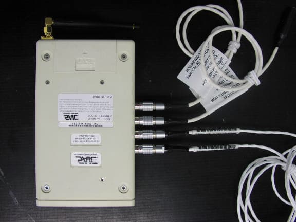
LPRPDE5
Feb 09, 2006Radio Dosimeter
Equipment Class
DSS - Part 15 Spread Spectrum Transmitter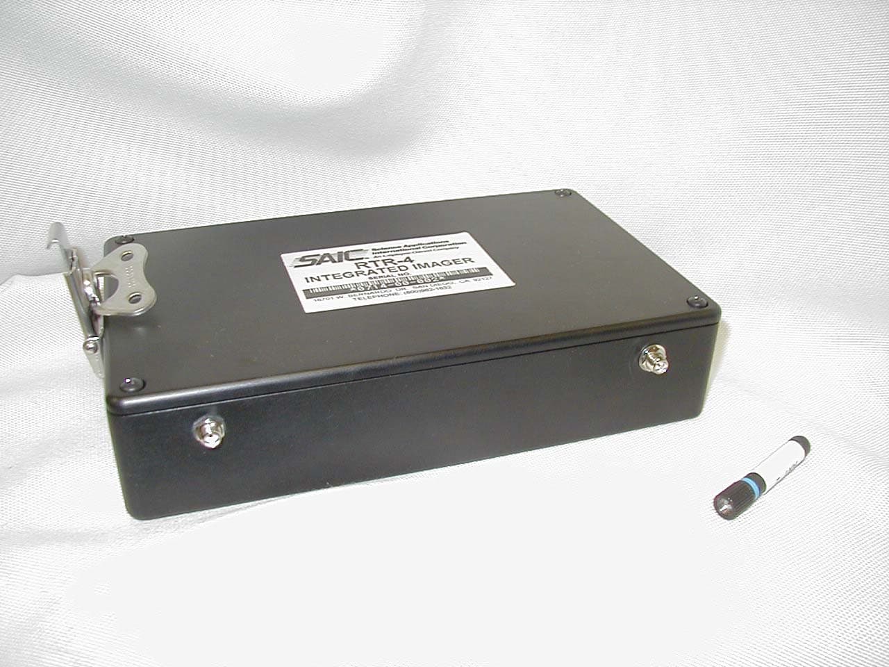
LPRRTR-4I
May 01, 2003Remote Control Transmitter
Equipment Class
DSC - Part 15 Security/Remote Control Transmitter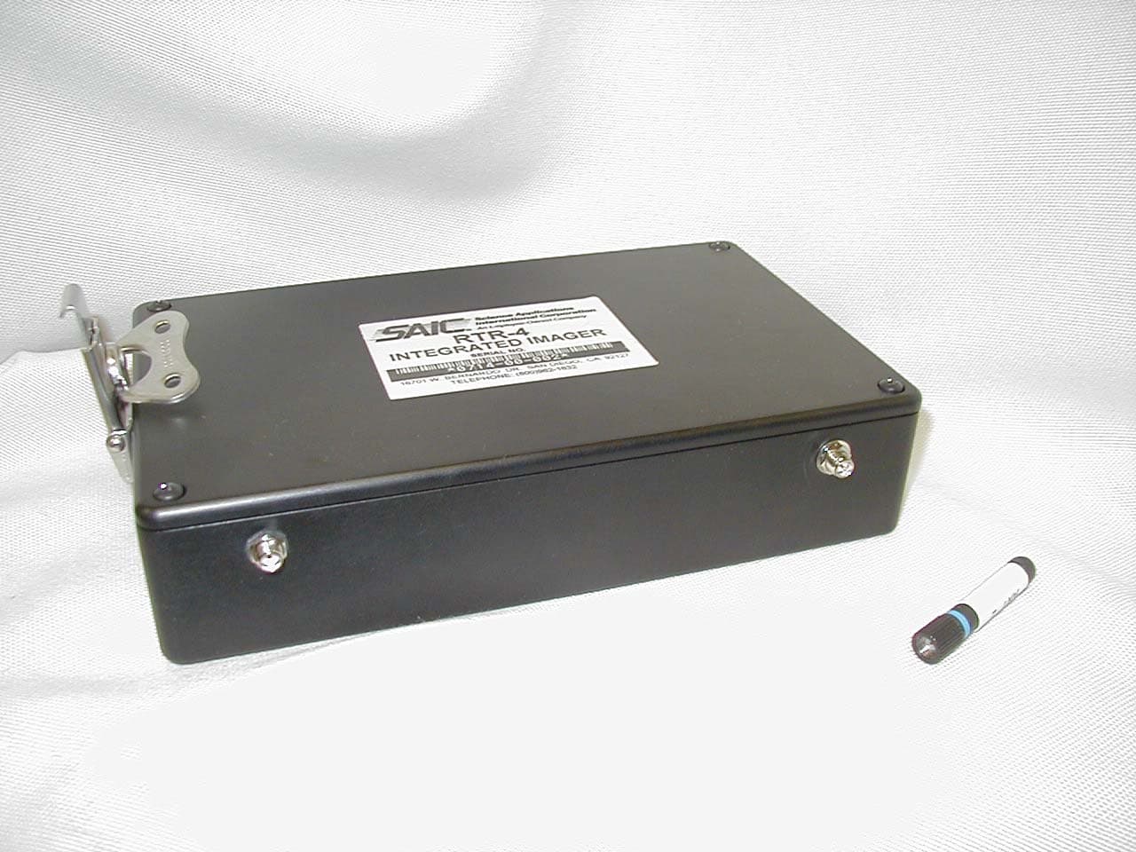
LPRRTR-RI
Apr 21, 2003Remote Control Transmitter
Equipment Class
DSC - Part 15 Security/Remote Control Transmitter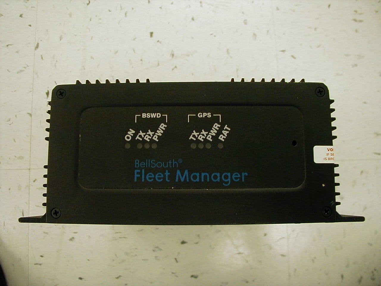
LPRLPR902M-ICU-0
Mar 27, 2001AVL GPS
Equipment Class
TNB - Licensed Non-Broadcast Station Transmitter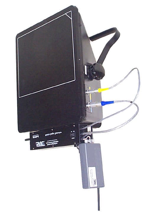
LPRRTR-4418M
May 23, 2000Wireless Security Transmitter
Equipment Class
DSC - Part 15 Security/Remote Control Transmitter