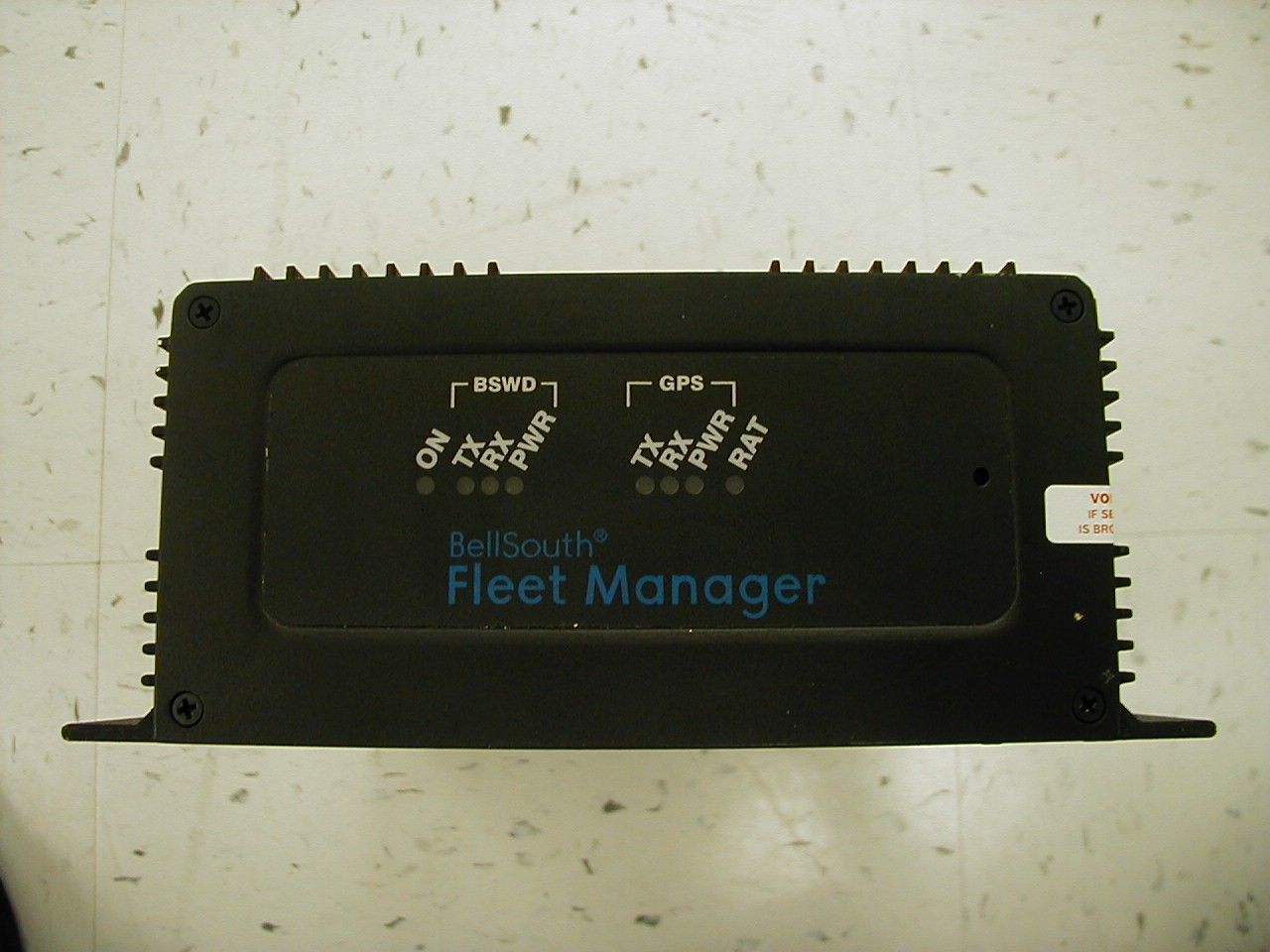
LPRLPR902M-ICU-0AVL GPS
Leidos, Inc.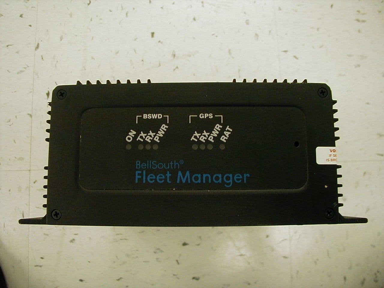
Click to zoom
Application Details
- Equipment Class
- TNB - Licensed Non-Broadcast Station Transmitter
- Date of Grant
- Mar 27, 2001
- Application Purpose
- Original Equipment
- Date of Application
- Jan 16, 2001
- Equipment Note
- AVL GPS
- Frequency Range
- 896.00000000 - 901.00000000
- Company
- Leidos, Inc.
- Country
- United States
Documents & Files
Document Text
Text extracted from the exhibit documents filed with the FCC. Open a document above to read the original.
Users Manual
ICU Terminal ICU Terminal 2000 SYMBOL TECHNOLOGIES, INC. All rights reserved. Symbol reserves the right to make changes to any product to improve reliability, function, or design. Symbol does not assume any product liability arising out of, or in connection with, the application or use of any product, circuit, or application described herein. No license is granted, either expressly or by implication, estoppel, or otherwise under any patent right or patent, covering or relating to any combination, system, apparatus, machine, material, method, or process in which Symbol products might be used. An implied license only exists for equipment, circuits, and subsystems contained in Symbol products. Symbol and the Symbol logo are a registered trademarks of Symbol Technologies, Inc. Other product names mentioned in this manual may be trademarks or registered trademarks of their respective companies and are hereby acknowledged. Symbol Technologies, Inc. One Symbol Plaza Holtsville, N.Y. 11742-1300 http://www.symbol.com Patents This product is covered by one or more of the following U.S. and foreign Patents: U.S. Patent No. 4,460,120; 4,496,831; 4,593,186; 4,603,262; 4,607,156; 4,652,750; 4,673,805; 4,736,095; 4,758,717; 4,816,660; 4,845,350; 4,896,026; 4,897,532; 4,923,281; 4,933,538; 4,992,717; 5,015,833; 5,017,765; 5,021,641; 5,029,183; 5,047,617; 5,103,461; 5,113,445; 5,130,520; 5,140,144; 5,142,550; 5,149,950; 5,157,687; 5,168,148; 5,168,149; 5,180,904; 5,216,232; 5,229,591; 5,230,088; 5,235,167; 5,243,655; 5,247,162; 5,250,791; 5,250,792; 5,260,553; 5,262,627; 5,262,628; 5,266,787; 5,278,398; 5,280,162; 5,280,163; 5,280,164; 5,280,498; 5,304,786; 5,304,788; 5,306,900; 5,321,246; 5,324,924; 5,337,361; 5,367,151; 5,373,148; 5,378,882; 5,396,053; 5,396,055; 5,399,846; 5,408,081; 5,410,139; 5,410,140; 5,412,198; 5,418,812; 5,420,411; 5,436,440; 5,444,231; 5,449,891; 5,449,893; 5,468,949; 5,471,042; 5,478,998; 5,479,000; 5,479,002; 5,479,441; 5,504,322; 5,519,577; 5,528,621; 5,532,469; 5,543,610; 5,545,889; 5,552,592; 5,557,093; 5,578,810; 5,581,070; 5,589,679; 5,589,680; 5,608,202; 5,612,531; 5,619,028; 5,627,359; 5,637,852; 5,664,229; 5,668,803; 5,675,139; 5,693,929; 5,698,835; 5,705,800; 5,714,746; 5,723,851; 5,734,152; 5,734,153; 5,742,043; 5,745,794; 5,754,587; 5,762,516; 5,763,863; 5,767,500; 5,789,728; 5,789,731; 5,808,287; 5,811,785; 5,811,787; 5,815,811; 5,821,519; 5,821,520; 5,823,812; 5,828,050; 5,850,078; 5,861,615; 5,874,720; 5,875,415; 5,900,617; 5,902,989; 5,907,146; 5,912,450; 5,914,478; 5,917,173; 5,920,059; 5,923,025; 5,929,420; 5,945,658; 5,945,659; 5,946,194; 5,959,285; 6,002,918; 6,021,947; 6,047,892; 6,050,491; 6,053,413; 6,056,200; 6,065,678; 6,067,297; 6,068,190; D305,885; D341,584; D344,501; D359,483; D362,453; D363,700; D363,918; D370,478; D383,124; D391,250; D405,077; D406,581; D414,171; D414,172, D419,548; D423,468; D424,035. Invention No. 55,358; 62,539; 69,060; 69,187 (Taiwan); No. 1,601,796; 1,907,875; 1,955,269 (Japan). European Patent 367,299; 414,281; 367,300; 367,298; UK 2,072,832; France 81/03938; Italy 1,138,713. rev. 06/00 1 Quick Reference Introduction The SAIC In-Vehicle Control Unit (ICU) is a rugged computer developed by Symbol for SAIC, and used as a platform for in- vehicle communications. It provides wireless network communications and two serial ports. The ICU uses an 80386 processor and supports an MS-DOS Operating System using industry standard protocols. About This Guide This manual describes the ICU’s basic features. Specific topics include: •Parts of an ICU on page 2 •Basic Operation on page 3 -Indicator Lights on page 3 -Ports and Connectors on page 4 -Resetting the ICU on page 5 •Driver Alert Features on page 6 •Basic Troubleshooting on page 8 •Service Information on page 10 Figure 1. ICU with Access Denial Cover in Place 2 ICU Terminal Parts of an ICU Symbol Parts The ICU has these parts and features provided by Symbol: • 2 MB of DRAM, expandable to 4MB • 2 MB Flash Drive, expandable to 8MB • RS-232 COM1 serial port • In-Vehicle Alert (IVA) port • 2 RAT Key Fobs • Connectors for RAT, GPS and BSWD antennas • Access Denial Cover • Quick Reference Guide SAIC Parts The ICU also requires these parts provided by SAIC: • RAT, GPS and BSWD antennas and cables • Power Input cable with 2 fuses • IVA cables • Manufacturing Mode cable for communication with a PC • Ground cable required for installation • Fasteners required for installation ICU Software The ICU terminal runs SAIC custom software from a DOS Operating System. 3 Quick Reference Basic Operation Indicator Lights A standard ICU terminal runs as a stand-alone device, with no keyboard or display. The front panel has eight LED indicator lights on that provide this status information (read from left to right): Figure 2. ICU Indicator Lights LEDDescription ONICU power indicator. BSWD TXDBSWD is transmitting. BSWD RXDBSWD is receiving. BSWD PWRBSWD has power. GPS TXDGPS is transmitting. GPS RXDGPS is receiving. GPS PWRGPS has power. RAT Remote Alert Transmitter mode/status. See Driver Alert Features on page 6 . Reset Button LEDs 4 ICU Terminal Por ts and Connectors The connector panel of the ICU unit has two ports, a power connector, the RAT programming button and three antenna connectors. The table describes these ports and connectors. Figure 3. ICU Ports and Connectors (SAIC model) ConnectorFunction COM1An RS-232 serial port with a 9-pin connector that can be used to communicate with devices such as laptop PCs. It connects to an RS-232 port on a Host PC using a specialized null modem cable. IVAA connector for the In-Vehicle Alert (IVA) cable. 12 VDCThe Power Input cable plugs into this connector to provides power to the unit. RAT Programming Button A recessed button that allows you to program the Remote Alert Transmitter (RAT). See page 6 for more information. RATA connector for the RAT radio antenna. GPSA connector for the GPS radio antenna. BSWDA connector for the BSWD (Mobitex) radio antenna. RAT…
Text truncated - open the document above for the full version.
Users Manual
Integrator’s Gui de RIM 902M OEM Radio Modem RIM 902M OEM Radio Modem Integrator’s Guide Last Updated: October 21, 1999 Model No. R902M-2-O © 1999, RESEARCH IN MOTION LIMITED Research In Motion and RIM are registered trademarks of Research In Motion Ltd. Mobitex is a trademark of the Swedish Telecommunications Administration. MS-DOS is a registered trademark, and Windows is a trademark, of Microsoft Corp. Warning: This document is for the use of licensed users only. Any unauthorised copying, distribution or disclosure of information is a violation of copyright laws. While every effort has been made to ensure technical accuracy, information in this document is subject to change without notice and does not represent a commitment on the part of Research In Motion Limited. Research In Motion 295 Phillip Street Waterloo, Ontario Canada N2L 3W8 tel. (519) 888-7465 fax (519) 888-7884 Email:[email protected] Web site: www.rim.net MOBITEX Interface, specified in Specification LZBA 703 1001, compatible equipment FCC Compliance Statement (USA) FCC Class B Part 15 This device complies with Part 15 of FCC Rules. Operation is subject to the following two conditions: 1. This device may not cause harmful interference, and 2. This device must accept any interference received, including interference that may cause undesired operation. Warning Changes or modifications to this unit not expressly approved by the party responsible for compliance could void the user’s authority to operate this equipment. This equipment has been tested and found to comply with the limits for a Class B digital device, pursuant to Part 15 of the FCC Rules. These limits are designed to provide reasonable protection against harmful interference in a residential installation. This equipment generates, uses and can radiate radio frequency energy and, if not installed and used in accordance with the manufacture’s instructions, may cause harmful interference to radio communications. There is no guarantee, however, that interference will not occur in a particular installation. If this equipment does cause harmful interference to radio or television reception, which can be determined by turning the equipment off and on, the user is encouraged to try to correct the interference by one or more of the following measures: • Re-orient or relocate the receiving antenna. • Increase the separation between the equipment and receiver. • Connect the equipment into an outlet on a circuit different from that to which the receiver is connected. • Consult the dealer or an experienced radio/TV technician for help. Industry Canada Certification This device complies with Industry Canada RSS 119, under certification number 2503195550A. IC Class B compliance This device complies with the Class B limits for radio noise emissions as set out in the interference-causing equipment standard entitled “Digital Apparatus,” ICES-003 of Industry Canada. Contents FCC Compliance Statement (USA) ........................................ i Industry Canada Certification ............................................... ii About this guide.................................................................... v 1. Introduction............................................................... 1 Radio performance...................................................................... 1 Mobitex network technology ....................................................... 4 2. Getting started........................................................... 7 Test board overview .................................................................... 8 How to connect the test board...................................................... 9 The MENU diagnostics tool .......................................................10 3. Mechanical integration ........................................... 19 Environmental properties...........................................................19 Physical properties .....................................................................20 Mounting methods .....................................................................20 Cables and connectors................................................................25 4. Power requirements ................................................ 29 Load specifications ....................................................................29 Calculating overall power consumption......................................31 Batteries ....................................................................................33 Plug-in supplies .........................................................................34 Automotive supplies...................................................................35 5. Interface specification ............................................. 37 MASC and RAP link-layer protocols .........................................37 Pin descriptions .........................................................................40 How to turn the radio on and off ................................................45 Loading firmware (optional) ......................................................46 6. Antenna selection .................................................... 49 Selecting an antenna ..................................................................49 Introduction to antenna terminology ..........................................51 Antenna design considerations...................................................53 Shielding ...................................................................................55 FCC radio frequency exposure rules...........................................56 Specifications ...................................................................... 61 Glossary of terms ................................................................ 63 About this guide This guide will assist you in integrating the RIM 902M OEM radio modem into a variety of devices such as laptop computers, handhelds, vending machines, point-of-sa…
Text truncated - open the document above for the full version.
Users Manual
Document No. 230086, Revision - 03 November 2000 Page 1 Telcordia Technologies, Inc. CONFIDENTIAL - RESTRICTED ACCESS This document and the confidential information it contains shall be distributed, routed or made available solely to authorized persons having a need to know within Telcordia Technologies, except with written permission of Telcordia Technologies 1 Introduction The SAIC In-Vehicle Control Unit (ICU) is a rugged computer developed by Symbol Technologies Inc. for Science Applications International Corporation (SAIC) and is used as a platform for in-vehicle communications. It provides wireless network communications, GPS positioning and Remote Alert Capability See Figure 1 WARNING To meet the FCC RF exposure requirement for mobile transmitters and specifically as it applies to BellSouth Fleet Manager Vehicle equipment configuration ensure that the antenna is at least 6 inches away from the vehicle operator or nearby persons when transmitting. The ICU uses an 80386 processor and supports the MS-DOS, Operating System using industry standard protocols. Figure 1 Front Panel View and Rear End view of ICU 1.1 About This Guide This manual describes how to: ??Prepare and install the HCU and associated hardware ??Program the Remote Alert Transmitter (RAT) Key Fobs ??Perform troubleshooting and maintenance activities 2 Parts of an ICU Figure 2 Front Panel of ICU Reset Button LEDs
Users Manual
Document No. 230086, Revision B 28 March 2001 Page A- 1 1 Introduction The SAIC In-Vehicle Control Unit (ICU, Model Number LCM386-20531200006 is a rugged computer developed by Symbol Technologies Inc. for Science Applications International Corporation (SAIC) and is used as a platform for in-vehicle communications. It provides wireless network communications, GPS positioning and Remote Alert Capability See Figure 1 WARNING: To meet the FCC RF exposure requirement for mobile transmitters as specified in the FCC’s Rules (47 CFR Section 2.1091) and specifically as it applies to BellSouth Fleet Manager Vehicle equipme nt configuration ensure that the antenna is at least 7.9 inches (20 cm) away from the vehicle operator or nearby persons when transmitting. The ICU uses an 80386 processor and supports the MS-DOS, Operating System using industry standard protocols. Figure 1Front Panel View and Rear Panel View of ICU 1.1 About This Guide This manual describes how to: 1. Prepare and install the HCU and associated hardware 2. Program the Remote Alert Transmitter (RAT) Key Fobs 3. Perform troubleshooting and maintenance activities
Attestation Statements
FCC Requirements for RF Radiation General Based on FCC rule 2.1091 and the FCC Guidelines for Human Exposure to Radio Frequency Electromagnetic Fields, OET Bulletin 65 including Supplement C, all mobile transmitting devices to routine environmental evaluation for radio frequency (RF) exposure prior to equipment authorization or use. For mobile devices that operate at frequencies of 1.5 GHz or below and whose Effective Radiated Power (ERP) is 1.5 watts or more are subject to routine environmental evaluation for RF exposure prior to equipment authorization or use. Although the ERP of the BellSouth ICU is well below 1.5 watts the evaluation for RF exposure was performed to ensure that all safety requirements were met and the BellSouth Fleet Manager system was found to be fully compliant. The BellSouth Fleet Manager In-vehicle control unit is classified by the FCC as a transmitting mobile device designed to be used such that a separation distance of at least 20 cm (~11 inches) is maintained between the body of the user and the antenna. In as much as our findings have determined that the energy levels are below this mandated threshold it is in the best interest of all parties to stay clear of the transmitting antenna during vehicle operations.
Block Diagram
386 PROCESSOR386 PROCESSOR CCACCA BSWD TRANSCIEVER RIM 902M L6AR902M-2-0 RAT RECEIVER KFR SAIC GPS RECEIVER CONEXTANT TU30-D140 RAT ANTENNA RM-433 MOBILEMARK (Receive Only) GPS ANTENNA SM-1575 MOBILEMARK (Receive Only) BSWD ANTENNA BMAX 9155S MAXRAD (Transmit/Receive) In-Vehicle Control Unit Antenna Plate LCM386-20531200006 12/24 VDC IGNITION SENSE IVA INPUTS (2) GROUND/RTN
Cover Letter(s)
Wireless Systems Group 4161 Campus Point Court, San Diego, California 92121 ® An Employee-Owned Company Science Applications International Corporations Wireless Systems Group TO: Mr. Errol ChangFebruary 9, 2001 FCC Application Processing Branch From: Mr. Bill Eaton SAIC Wireless Systems Group Subject: Submittal for FCC ID LPRLPR902M-ICU-0 731 Confirmation Number : EA99776 Correspondence Reference Number: 17946 Sir: In response to item 3 of correspondence Reference number 17946 please accept this document as a brief description of the device function. The In-Vehicle Control Unit (ICU) designed for the BellSouth Global Positioning System is scheduled to be deployed across the nine state area serviced by BellSouth Telecommunications in support of their installation and maintenance fleet. The ICU system configuration is based on commercially available technology that is hosted in a vehicle-mounted enclosure that has been designed and tested to meet these industry standards: 1. Joint SAE/TMC Recommended Environmental Practices for Electronic Equipment Design (Heavy-Duty Trucks) Document No. SAE J1455. 2. Code of Federal Regulations, Federal Communications Commission, Subchapter A, General, Part 15 and Part 90. 3. Surface Vehicle Electromagnetic Compatibility (EMC) Standards Manual, SAE HS-3600, 1999 Edition. The ICU Model Number LCM386-20531200006 manufactured by Symbol Technologies, Inc. for Science Applications International Corporation in support of this program complies with Part 15 of the FCC rules and thus is appropriately ma r ke d . The ICU contains a 12 channel GPS receiver manufactured by Conexant, Remote Alert Receiver manufactured by Street Smart Security, and a BSWD Wireless Modem manufactured by Research In Motion (RIM). The use of the GPS receiver (TU30-D140) in the ICU is passive, requiring no intervention or activity by the technician. Periodically, the in-vehicle system GPS/vehicle data is communicated through the BSWD (now Cingular Wireless) wireless network utilizing the RIM 902M transceiver (FCC ID: L6AR902M-2-0) to update the GPS Server Function located in the BellSouth data center. The ICU also provides the technician with a remote emergency alert capability by hosting a Remote Alert Receiver that can be activated up to 150 feet in line of sight of the vehicle utilizing an FOB transmitter (FCC ID:KFR-SAIC). The data center back office system is also capable of monitoring vehicle activities and reporting exceptions that are generated when measured data deviates beyond specified nominal tolerances. Wireless Systems Group 4161 Campus Point Court, San Diego, California 92121 The ICU system accumulates positional information and sends reports to the data center based on time and distance thresholds established by the data center staff. The ICU only operates while the vehicle ignition is in the on position and normally is maintained in a power down state when the vehicle is not being operated. The antenna system associated with the ICU is mounted on the exterior of the BellSouth fleet vehicles.. Utilizing an antenna plate the mounting location of the antennas associated w ith the ICU are controlled through mechanical design, installation procedures and installation training to ensure that the external placement of the antennas is such that a safe distance of six inches is maintained between the antennas, vehicle operator and nearby persons. To preclude installation defects of the antenna cabling that could result in unacceptable VSWR all RF cables are preterminated to a uniform length. This uniform length (14 feet) ensures that the energy delivered to the antenna remains consistent with our design requirements and is not subject to on-site modification. Specific to the RIM902M- 2-0 RF path SAIC part number 230030-1 REV (B) identifies the cable manufactured to our specifications by Maxrad, Inc., which is terminated in the BMAX 9155S Antenna also of Maxrad, Inc. for the entire fleet. The preferred mounting location for the ICU is the vehicle cab behind the passenger seat mounted vertically on the rear wall or cage. The ICU cable connections are protected by an Access Denial Plate and strain relief to preclude any inadvertent disconnection of the system cabling. Required Torque settings for the RF connections are included in the installation documentation and training. The Grant of Equipment Authorization-Certification FCC identifier L6AR902M-2-0 states approval of the RIM902M- 2-0 operating with three different antenna types and a 1 dB loss cable or greater. Two of these antenna types are listed as 3 dBd gain antennas. As a matter of comparison we are operating the RIM902M-2-0 with a 4 dBd antenna and a cable configuration w hich a 3dB loss. A review of the Maximum Permissible Exposure Evaluation with respect to FCC Rule Part 47CFR 2.1091 for the R902M-2-0 conducted by the APREL Laboratories and a matter of public record as made available on the FCC OET website has been conducted by SAIC. In addition the APREL Laboratories and EESI Laboratories both qualified FCC certification organizations have been consulted as an independent sources on our specific application and filing to ensure that we have high confidence that we are in compliance with the FCC requirement. Due to the nature and specific restrictions (antennas and cable lengths) outlined in the Grant of Equipment Authorization-Certification FCC identifier L6AR902M-2-0 for the RIM 902M-2-0 transceiver we respectfully request an unique FCC Identifier LPRLPR902M-ICU-0 be granted to identify our product as configured. It is SAIC’s understanding that the MPE/SAR testing previously conducted on the RIM 902M-2-0 radio and as referenced in our Application for Equipment Authorization is valid for the proposed filing as we have made no modifications to the device. Respectfully, Bill Eaton Wireless Systems Group 4161 Campus Point Court, San Diego, California 92121
ID Label/Location Info
Explanation of ICU Label. The ICU Label will be modified to change the Manufacturer from Symbol Technologies to SAIC. A bottom line will be added to this Label and will indicate FCC ID: LPRLPR902-M- ICU-0. Due to file transfer size restraints we were unable to modify the jpeg file and add these textual comments to the existing label.
RF Exposure Info
FCC Requirements for RF Radiation General Based on FCC rule 2.1091 and the FCC Guidelines for Human Exposure to Radio Frequency Electromagnetic Fields, OET Bulletin 65 including Supplement C, all integrators of the RIM OEM unit are subject to routine environmental evaluation for radio frequency (RF) exposure prior to equipment authorization or use. For mobile devices that operate at frequencies of 1.5 GHz or below and whose Effective Radiated Power (ERP) is 1.5 watts or more are subject to routine environmental evaluation for RF exposure prior to equipment authorization or use. Although the ERP is well below 1.5 watts (as shown below), the evaluation for RF exposure was performed. The ICU is classified by the FCC as a mobile device. This classification identifies the ICU as a transmitting device designed to be used such that a separation distance of at least 20 cm is maintained between the body of the user and the antenna. For a mobile device the human exposure to the RF radiation can be evaluated in terms of Maximum Permissible Exposure (MPE) limits for power density in mW/cm 2 . Since the ICU transmits randomly with respect to the vehicle operator (that is, it is not controlled by the technician), the FCC defines this as an Uncontrolled Environment. The MPE limit at 900 MHz for an Uncontrolled Environment is 0.6 mW/cm 2 . Analysis The following data is used to calculate the ERP and the MPE of the vehicle system for the FCC specified 30 minute interval: RIM 902M Transmit Power = 2 watts = 3 dBW Antenna Gain = 4 dBd Cable and Connector Loss = 3 dB Duty Cycle (Worst Case) = See below For our worst-case (1) analysis, we assumed the vehicle was out of BSWD coverage for 5 days and had accumulated 1500 events to report. We assumed it drove into BSWD coverage at 60 MPH, with the default reporting parameters of 800 meters or 5 minutes set. In this case the duty cycle is 10.75% for 30 minutes. Our second analysis (2), was based on a bucket truck, with the default parameters set, which remains stationary for 30 minutes. In this case, the technician can be outside the vehicle cab, potentially working near the BSWD antenna. The duty cycle is 0.29% for 30 minutes. ERP = (Transmit Power + Antenna Gain – Cable Loss) x Duty Cycle ERP 1 = (3 + 4 – 3)(0.1075) = 4 dBW x 0.1075 = 0.270 Watts ERP 2 = (3 + 4 – 3)(0.0028) = 4 dBW x 0.0029 = 0.007 Watts Power at the antenna = (Transmit Power – Cable Loss) x Duty Cycle P ant(1) = (3 – 3)(0.1075) = 0 dBW x 0.1075 = 0.1075 Watts P ant(2) = (3 – 3)(0.0028) = 0 dBW x 0.0029 = 0.0029 Watts Using the MPE calculator at http://n5xu.ae.utexas.edu/rfsafety/ , the distances corresponding to an MPE of 0.6 mW/cm 2 can be calculated. For the worst case 1, a person would be required to remain more than 5.3 inches from the antenna. For case 2, a person would be required to remain more than 1 inch from the antenna. Therefore, in both cases, the FCC-mandated minimum of 20 cm (approximately 7.9 inches) will be recommended. This information will be included in the technician training, user and installation documentation associated with the equipment. These actions are considered adequate to meet the safety criteria as outlined in FCC OET Bulletin 65.
RF Exposure Info
Certification Report on Maximum Permissible Exposure Evaluation with Respect to FCC Rule Part 47CFR §2.1091 Research in Motion Ltd. R902M-2-O Radio Modem and 3dBd Larsen NMO 3E 900B SMA Antenna Date: 25 March, 1999 51 Spectrum Way Nepean ON K2R 1E6 Tel: (613) 820-2730 Fax: (613) 820-4161 email: [email protected] This report shall not be reproduced, except in full, without the express written approval of APREL Laboratories. FCC Rule Part 47CFR §2.1091OEM Radio-Modem March 12, 1999Page 3© APREL Project #: RIMB- R902M2O Larsen NMO 3E 900B SMA -3167 Since 1981 Research · Training · Consulting · Testing “ Solutions for the Wireless Future FCC ID:L6AR902M-2-O Client :Research in Motion Limited Equipment :OEM Radio-Modem attached to a Larsen Vehicle-Top Mounting Antenna Part No. :R902M-2-O Radio-Modem and NMO 3E 900B SMA Antenna Serial No. :Pre-production sample ENGINEERING SUMMARY This report contains the results of the maximum permissible exposure (MPE) evaluation performed on the equipment under test (EUT) which was comprised of a Research in Motion R902M-2-O OEM radio-modem, an IBM 760ED ThinkPad laptop, attached to a Larsen Vehicle- Top Mounting Antenna. The tests were carried out in accordance with the applicable requirements of FCC rules found in 47CFR §2.1091 and the standards ANSI/IEEE C95.1-1992 and C95.3-1992. The methodology and results for the test are described in the appropriate section of this report. The EUT will not exceed the MPE requirements beyond a distance of 23 cm for 896 - 901MHz band. FCC Rule Part 47CFR §2.1091OEM Radio-Modem March 12, 1998Page 4© APREL Project #: RIMB- R902M2O Larsen NMO 3E 900B SMA -3167 Research * Training * Consulting * Testing Solutions for the Wireless Future Since 1981 TABLE OF CONTENTS 1.ACRONYMS................................................................................................................5 2.INTRODUCTION.........................................................................................................6 2.1.GENERAL............................................................................................................6 2.2.SCOPE..................................................................................................................6 2.3.SCHEDULE..........................................................................................................6 2.4.APPLICABLE DOCUMENTS..............................................................................6 3.TEST SAMPLE.............................................................................................................7 4.GENERAL REQUIREMENTS.....................................................................................8 4.1.LOCATION OF TEST FACILITIES.....................................................................8 4.2.PERSONNEL........................................................................................................8 4.3.FAILURE CRITERIA...........................................................................................8 4.4.POWER SOURCE REQUIRED............................................................................9 4.5.TOLERANCE.......................................................................................................9 5.TEST INSTRUMENTATION & CALIBRATION........................................................9 5.1.GENERAL............................................................................................................9 5.2.MPE TEST EQUIPMENT REQUIRED................................................................9 5.3.CALIBRATION REQUIREMENTS.....................................................................9 6.ELECTRICAL/MECHANICAL DESCRIPTION........................................................10 6.1.TEST UNIT DESCRIPTION...............................................................................10 6.2.MPE TEST SETUP.............................................................................................10 7.MAXIMUM PERMISSIBLE EXPOSURE (MPE) TEST............................................12 7.1.PURPOSE...........................................................................................................12 7.2.TEST EQUIPMENT............................................................................................12 7.3.CRITERIA...........................…
Text truncated - open the document above for the full version.
Contact Information
Applicant
Dan Sweeney(Assistant General Counsel)
Technical Contact
Science Applications International CorporationWilliam S Eaton
[email protected](858) 826-9019
4161 Campus Point Court · San Diego, California · United States
Non-Technical Contact
Science Applications International CorporationVirgil K Bertel
[email protected](858) 826-3745
Technical Specifications
| # | Rule Parts | Frequency Range | Power Output | Emission | Tolerance |
|---|---|---|---|---|---|
| 1 | 90 | 896 MHz - 901 MHz | 2 W | 12K8F1D | 1.5000000000 ppm |
Other Applications from Leidos, Inc.
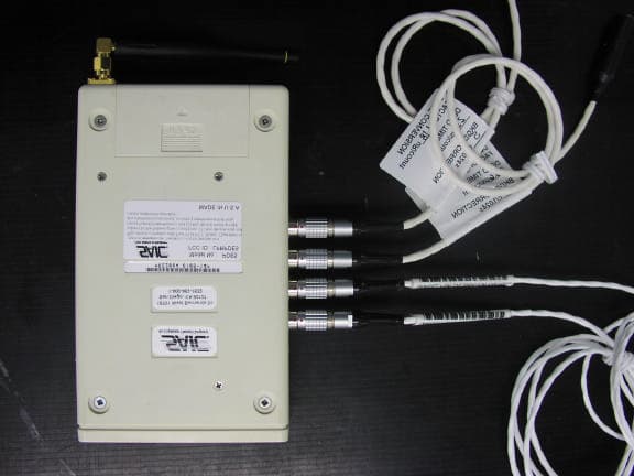
LPRPDE5
Feb 09, 2006Radio Dosimeter
Equipment Class
DSS - Part 15 Spread Spectrum Transmitter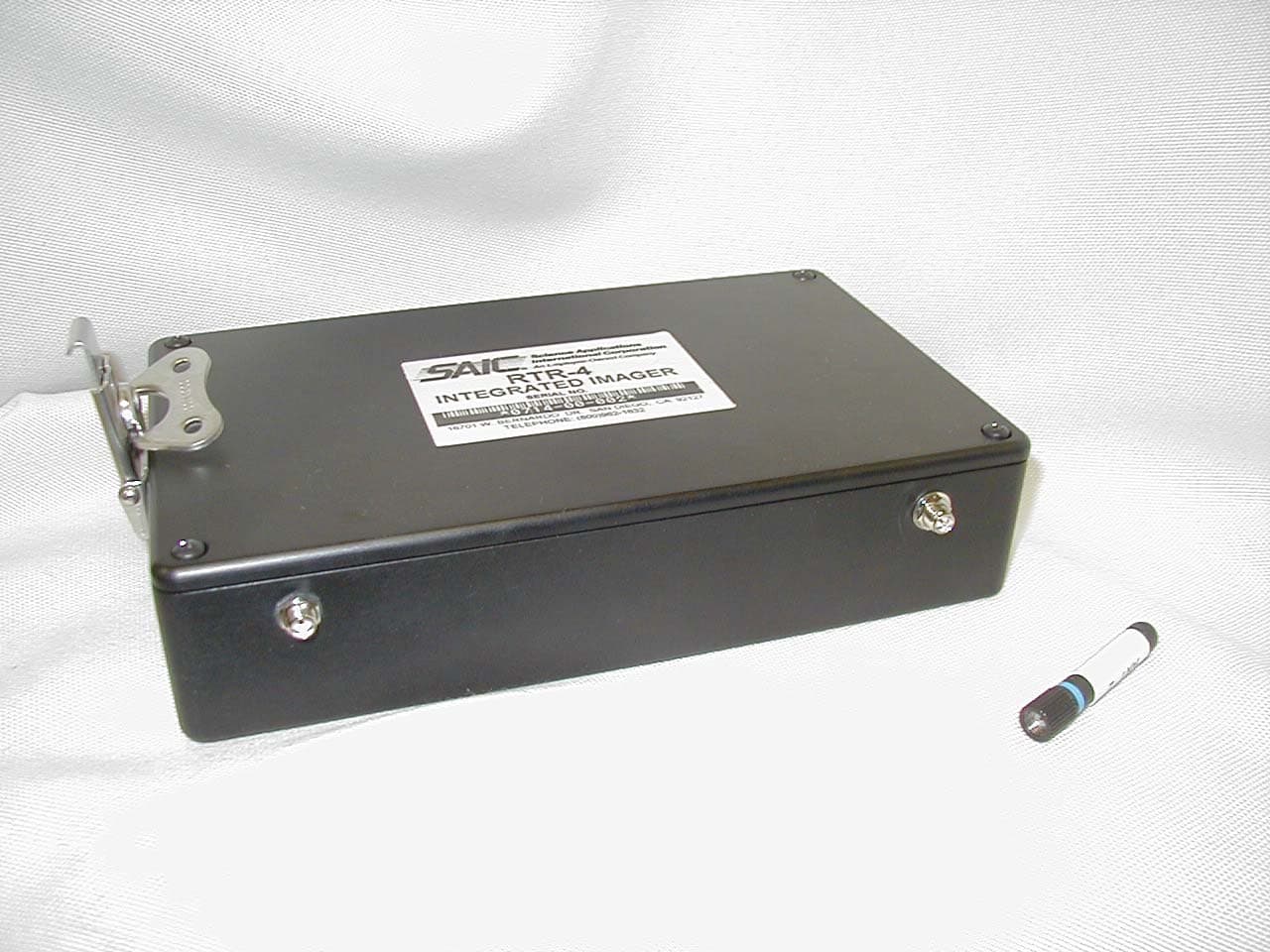
LPRRTR-4I
May 01, 2003Remote Control Transmitter
Equipment Class
DSC - Part 15 Security/Remote Control Transmitter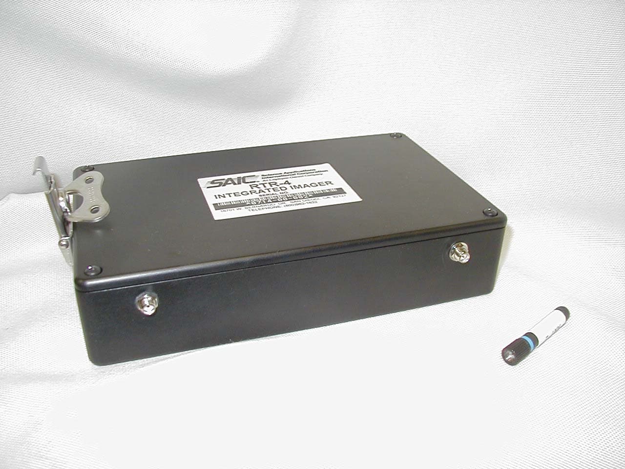
LPRRTR-RI
Apr 21, 2003Remote Control Transmitter
Equipment Class
DSC - Part 15 Security/Remote Control Transmitter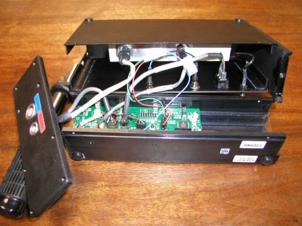
LPR418M1
Jul 11, 2002RTR-4 Wireless Option
Equipment Class
DSC - Part 15 Security/Remote Control Transmitter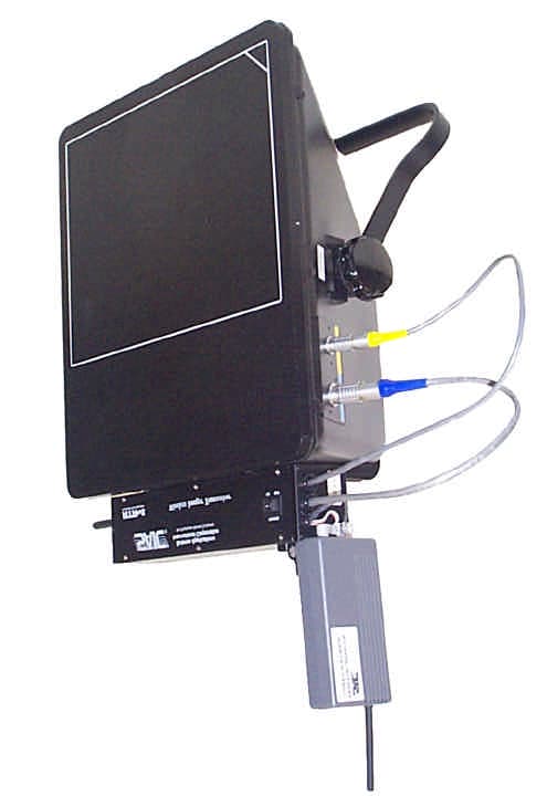
LPRRTR-4418M
May 23, 2000Wireless Security Transmitter
Equipment Class
DSC - Part 15 Security/Remote Control Transmitter