LPRPDE5Radio Dosimeter
Leidos, Inc.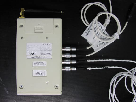
Click to zoom
Application Details
- Equipment Class
- DSS - Part 15 Spread Spectrum Transmitter
- Date of Grant
- Feb 09, 2006
- Application Purpose
- Original Equipment
- Date of Application
- Feb 09, 2006
- Equipment Note
- Radio Dosimeter
- Frequency Range
- 910.50000000 - 917.70000000
- Company
- Leidos, Inc.
- Country
- United States
Documents & Files
Document Text
Text extracted from the exhibit documents filed with the FCC. Open a document above to read the original.
Users Manual
Safety & Security Instruments A Division of Science Applications International Corporation OPERATION & MAINTENANCE MANUAL RADSTAR SYSTEM MODELS PD-4, PDE-4 AND PDX-4 16701 West Bernardo Drive San Diego, CA 92127 Rev: 010695 (800) 962-1632 or (858) 826-9831 Drawing 201313 SAIC PROPRIETARY - Use or disclosure of the information contained on this page is subject to the restrictions contained on the cover sheet of this document. Page1 SAIC PROPRIETARY - Use or disclosure of the information contained on this page is subject to the restrictions contained on the cover sheet of this document. Page2 USER'S FCC NOTICE This equipment has been tested and found to comply with the limits for a Class B digital device, pursuant to Part 15 of FCC Rules. These limits are designed protection against harmful interference in a residential installation. This equipment generates, uses and can radiate radio frequency energy and, if not installed and used in accordance with the instructions, may cause harmful interference to radio communications. However, there is no guarantee that interference will not occur in a particular installation. If this equipment does cause harmful interference to radio or television reception, which can be determined by turning the equipment off and on, the user is encouraged to try to correct the interference by one or more of the following measures: • Reorient or relocate the receiving antenna. • Increase the separation between the equipment and receiver. • Connect the equipment into an outlet on a circuit different from that to which the receiver is connected. • Consult the dealer or an experienced radio/TV technician for help. Shielded cables and I/O cords must be used for this equipment to comply with the relevant FCC regulations. Changes or modifications not expressly approved in writing by Science Applications International Corporation may void the user's authority to operate this equipment. SAIC PROPRIETARY - Use or disclosure of the information contained on this page is subject to the restrictions contained on the cover sheet of this document. Page3 RadStar TM Radio Transmission Dosimetry System PREFACE Congratulations! You have made an excellent purchase decision. Science Applications International Corporation's (SAIC's) RadStar™ system will provide improved remote radiation monitoring performance which enables: • New levels of ALARA conformance • Minimum staffing and training requirements • Rapidly deployable monitoring • Cost effective spot monitoring • Outage time reduction • Improved safety In addition, SAIC is committed to providing the total support net required for such a system which can be accessed by calling (800)-962-1632. Enough flexibility has been designed into the RadStar™ Radio Dosimetry system to handle a wide range of remote monitoring applications. Although simple networks can be powered up and run without modifying the factory default configuration, setting up the more complex network architectures will usually require some reconfiguration of operating parameters within the PD-4s™ and PDE-4s™ [or simply, PD(E)-4] teledosimeters. For this purpose, SAIC recommends the use of the included PDRC4 application program which allows users to edit control settings within the PD(E)-4 via a PDR-1™ or PDR- 1/S™ Reader. After the network has been configured, it can be monitored and controlled by the RadStar™ application program, RS which is also included. Both RS and PDRC4 are compatible with and can be interfaced to user written applications. Both of these application programs are referenced in this manual to provide a context for describing configuration and control operations. A limited amount of descriptive material concerning the use of these programs is contained herein; however, both are provided with on-line Help which will provide additional details concerning active keys, editing procedures, and setup procedures. SAIC PROPRIETARY - Use or disclosure of the information contained on this page is subject to the restrictions contained on the cover sheet of this document. Page4 1.0 INTRODUCTION The RadStar™ System is the most advanced radio transmission dosimetry system available, providing detection, radio transmission, and remote display of radiation exposure information. RadStar™ is unique in its use of BIDIRECTIONAL transmissions for high communication reliability at low RF power levels, minimizing the potential for electromagnetic interference. The primary application for RadStar™ is remote monitoring of personnel working under severe radiation conditions where accurate radiation dosimetry is difficult. Typical monitoring problems solved by RadStar™ include situations involving • high radiation field gradients, • radiation fields that are difficult to characterize with a high level of confidence, and • potentially high radiation fields that vary with time. A secondary application for RadStar™ Dosimeters is as local area monitors. Each RadStar™ Dosimeter is equipped with an external power jack, thus allowing it to monitor specific points of interest, unattended, for the duration of an outage. Alternatively, RadStars™ can be temporarily placed to monitor the progress of processes such as chemical decontamination. From its inception, the RadStar™ concept has been entirely consistent with the spirit of ALARA. RadStar™ allows the Health Physicist and his staff to monitor the progress of sensitive tasks from outside the control area. RadStar™ products, like the PDE-4™ with 5 parallel radiation measurement channels, allow the HP to simultaneously monitor trunk and extremity doses as the radiation worker performs his task. Thus, unplanned doses due to field gradients, hot spots, and time variant conditions can be detected and remediated immediately. RadStar™ can reduce personnel doses in yet other ways. Accurate, real time monitoring allows contingencies to be reduced, and in cases where the worker still has allowable dose after completion of a task, he can move on t…
Text truncated - open the document above for the full version.
Users Manual
SUPPLEMENTAL DATA TO THE OPERATION & MAINTENANCE MANUAL RADSTAR SYSTEM MODELS PD-4, PDE-4 AND PDX-4 FOR THE PDE-5 and PDX-5 16701 West Bernardo Drive Date: Feb 1 2006 San Diego, CA 92127 Dwg: 201313S PDE5 FCC NOTICE LPRPDE5 INFORMATION TO USER This device complies with Part 15 of the FCC Rules. Operation is subject to the following two conditions: (1) This device may not cause harmful interference, and (2) This device must accept any interference received, including interference that may cause undesired operation. This equipment has been tested and found to comply with the limits for Class A Digital Device, pursuant to Part 15 of the FCC Rules. These limits are designed to provide reasonable protection against harmful interference in a residential installation. This equipment generates and can radiate radio frequency energy and, if not installed and used in accordance with the instructions, may cause harmful interference to radio communications. However, there is no guarantee that interference will not occur in a particular installation. If this equipment does cause harmful interference to radio or television reception, which can be determined by turning the equipment off and on, the user is encouraged to try to correct the interference by one or more of the following measures. • Reorient or relocate the receiving antenna • Increase the separation between the equipment and receiver • Connect the equipment into an outlet on a circuit different from that to which the receiver is connected • Consult the dealer or an experienced radio/TV technician for help Any changes or modifications not expressly approved by the party responsible for compliance could void the user’s authority to operate the equipment. This device falls below the power requirements for Specific Absorption Rate (SAR) test ing and may be worn within 2cm of the body. WARNING: The PDX-5 is approved only for mobile and base station transmitting devices, separation distances of (i) 20 centimeters or more for antennas with gains < 6 dBi or (ii) 2 meters or more for antennas with gains = 6 dBi should be maintained between the antenna of this device and nearby persons during operation. To ensure compliance, operation at distances closer than this is not recommended PDX-5 FCC NOTICE OUR9XSTREAM INFORMATION TO USER This device complies with Part 15 of the FCC Rules. Operation is subject to the following two conditions: (1) This device may not cause harmful interference, and (2) This device must accept any interference received, including interference that may cause undesired operation. This equipment has been tested and found to comply with the limits for Class B Digital Device, pursuant to Part 15 of the FCC Rules. These limits are designed to provide reasonable protection against harmful interference in a residential installation. This equipment generates and can radiate radio frequency energy and, if not installed and used in accordance with the instructions, may cause harmful interference to radio communications. However, there is no guarantee that interference will not occur in a particular installation. If this equipment does cause harmful interference to radio or television reception, which can be determined by turning the equipment off and on, the user is encouraged to try to correct the interference by one or more of the following measures. • Reorient or relocate the receiving antenna • Increase the separation between the equipment and receiver • Connect the equipment into an outlet on a circuit different from that to which the receiver is connected • Consult the dealer or an experienced radio/TV technician for help Any changes or modifications not expressly approved by the part y responsible for compliance could void the user’s authority to operate the equipment. PREFACE Since many of the PDE-4 and PDX-4 systems are still in use today and the basic operation of the system does not change after upgrading to PDE-5 and PDX-5, this supplement is not intended to replace the RadStar™ manual. This supplement highlights areas where the PDE-5 and PDX-5 differ from the PDE-4 and PDX-4. 1.0 Introduction The new MaxStream modem was integrated into the system in a manner that allowed continued operation with existing software which makes the change nearly transparent to the operators and users. The PDE-4 is upgraded by replacing the PROXIM RF Modem with a MaxStream RF Modem and adding a code translation PWA. The translation PWA converts the original software / firmware codes into codes understood by the new MaxStream RF Modem. The PDX-4 Base Station can not be upgraded and is replaced with a completely new PDX-5 Base Station that incorporates the new MaxStream RF Modem and the code translation PWA. Additionally a USB port was added for ease of use with more modern computers. PDE/X-4 units will not communicate with a PDE/X-5; therefore the new upgrade is not backwards compatible with existing units. It is backwards compatible with the existing operating software including Barletts software. 2.0 Functional Changes The following data highlights functional differences between the PROXIM and MaxStream RF Modems. PROXIM MAXSTREAM Notes Technical Specifications Indoor/Urban Range 800' 1500' RF Output Power 300 mW 150 mW Battery Life for PDE @ 10 second interval 8 hours 16.9 hours (by calculation) Assuming a 625 mAh battery and 37 mA draw Weight (PDE) 396g (14oz) 347g (12.24oz) RadStar™ Radio Transmission Dosimetry System PDE-5 and PDX-5 Manual Supplement 3.0 System Setup Changes The following data highlights setup differences between the PROXIM and MaxStream RF Modems. NONE 4.0 Software Interface Changes The following table highlights operating software differences between the PROXIM and MaxStream RF Modems. PROXIM MAXSTREAM Notes Operating Instructions Adjusting Settings (PDX) Open Terminal, Press White button Open Terminal program, Press Reset Button, Type "+++" Interface (PDX) Serial Serial or USB USB can be enabled or disabled in Terminal …
Text truncated - open the document above for the full version.
ID Label/Location Info
LABEL REQUIREMENTS RF IC & FCC COMPANY NAME Model No.: PDE5 IC: 6341A-PDE5 FCC ID: LPRPDE5 * This device complies with Part 15 of the FCC Rules. Operation is subject to the following two conditions: (1) This device may not cause harmful interference, and (2) This device must accept any interference received, including interference that may cause undesired operation. Made in XXXXXX ** If label format is not in full scale, please indicate the dimensions of the label. MUST APPEAR ON THE OUTSIDE OF THE CERTIFIED UNIT. ALL INFORMATION MUST APPEAR ON THE LABEL.
Operational Description
The RCL Series is useful in products where additional height above the product’s case is needed or a slightly wider operational bandwidth is desired. The 916MHz version has a 1/4-wave element. Features Right-angle mount Excellent performance Omni-directional pattern Fully weatherized Rugged & damage-resistant Part 15 compliant RP-SMA connector Available in black or custom colors Use with plastic* or metal enclosures ANT-916-CW-RCL DATA SHEET Product DimensionsDescription Plots Antenna Factor575 S.E. Ashley Place Grants Pass, OR 97526-3237 www.antennafactor.com 541-956-0931 (phone) 541-471-6251 (fax) Rev 09-08-05 AzimuthElevationTypical VSWR 270 90 180 0 -30dB -25dB -20dB -15dB -10dB - 5dB 0dB 5dB 10dB 270 90 180 0 -30dB -25dB -20dB -15dB -10dB - 5dB 0dB 5dB 10dB Coming Soon Coming Soon Coming Soon Coming Soon * Requires proximity ground plane 0.24” (6.0) 3.46” (88.0) 0.31” (8.0) 0.42” (10.6) Center Freq. Bandwidth Wavelength VSWR Impedance Gain Connector 916MHz 150MHz 1/4-wave <1.7 typ. at center 50 ohms 2.40dBi RP-SMA Note: Electrical specifications and plots measured on 4” x 4” reference ground plane Ordering Information ANT-916-CW-RCL Electrical Specifications CENTER 900.000MHz SPAN 200.000MHz S11 SWR 1.654
RF Exposure Info
Source Based Time Averaged Output Power This is a frequency hopping spread spectrum transceiver designed for operation in the 902 to 928 MHz band. It transmits with a peak conducted output power of 0.072 watt into a 2.4 dBi antenna resulting in a peak eirp of 10(2.4/10) x 0.072 = 0.125 watt eirp. The maximum dwell time is 0.160 seconds and the hop rate is 2.5 hops per second giving a duty cycle of 2.5 x 0.160 = 0.4 Therefore the source based time average output power is 0.4 x 0.125 = 0.050 watt This is 50 mW eirp and this is below the general population low threshold for SAR evaluation 60/0.928 = 65 mW eirp. Reference: Appendix A: TCB Exclusion List, Revised 17 July 2002
Test Report
Nemko USA, Inc. 11696 Sorrento Valley Rd., Suite F San Diego, CA 92121-1024 Phone (858) 755-5525 Fax (858) 452-1810 FCC Part 15 Subpart C, 15.247 : February 2005 Test Report: 2005 110815-FCC-C Project number: 25-815-SAI Applicant: Science Applications International Corporation 16701 W. Bernardo Rd. San Diego, CA 92127 For The Radio Docimeter Model: PDE5 FCC ID: LPRPDE5 In Accordance With: FCC Part 15 Subpart C, 15.247 FHSS System and Digitally Modulated Radiators 902-928MHz, 2400 - 2483.5 MHz, 5725- 5850MHz Date: 11-14-05 Total Number of Pages: 34 Nemko USA, Inc. 11696 Sorrento Valley Road, Suite F, San Diego, CA 92121 Phone (858) 755-5525 Fax (858) 452-1810 Report Number: Order Number FCC ID: FCC ID # LPRPDE5 Specification: FCC Part 15 Subpart C, 15.247 Page 2 of 34 Report Summary These tests were conducted on a sample of the equipment for the purpose of demonstrating compliance with Part 15; Subpart C. Radiated tests were conducted is accordance with ANSI C63.4-2003. Radiated emissions are made on an open area test site. A description of the test facility is on file with the FCC. The assessment summary is as follows: Apparatus Assessed: Radio Docimeter Model PDE5 Specification: FCC Part 15 Subpart C, 15.247 Compliance Status: Complies Exclusions: None Non-compliances: None Report Release History: REVISION DATE COMMENTS - 11-14-05 Prepared By: A. Laudani - 11-14-05 Initial Release: Note that the results contained in this report relate only to the items tested and were obtained in the period between the date of initial receipt of samples and the date of issue of the report. This test report has been completed in accordance with the requirements of ISO/IEC 17025. Nemko USA Inc. authorizes the applicant to reproduce this report provided it is reproduced in its entirety and for use by the company’s employees only. Any use which a third party makes of this report, or any reliance on or decisions to be made based on it, are the responsibility of such third parties. Nemko USA Inc. accepts no responsibility for damages, if any, suffered by any third party as a result of decisions made or actions based on this report. Nemko USA, Inc. 11696 Sorrento Valley Road, Suite F, San Diego, CA 92121 Phone (858) 755-5525 Fax (858) 452-1810 Report Number: Order Number FCC ID: FCC ID # LPRPDE5 Specification: FCC Part 15 Subpart C, 15.247 Page 3 of 34 TABLE OF CONTENTS Report Summary........................................................................................................................................2 Section 1: Equipment Under Test.............................................................................................................4 1.1 Product Identification.......................................................................................................................4 1.2 Samples Submitted for Assessment................................................................................................4 1.3 Theory of Operation.........................................................................................................................5 1.4 Technical Specifications of the EUT................................................................................................6 1.5 Block Diagram of the EUT...............................................................................................................6 Section 2: Test Conditions.........................................................................................................................7 2.1 Specifications...................................................................................................................................7 2.2 Deviations From Laboratory Test Procedures.................................................................................7 2.3 Test Environment.............................................................................................................................7 2.4 Test Equipment................................................................................................................................8 Section 3: Observations..............................................................................................................................9 3.1 Modifications Performed During Assessment.................................................................................9 3.2 Record Of Technical Judgements...................................................................................................9 3.3 EUT Parameters Affecting Compliance...........................................................................................9 3.4 Test Deleted....................................................................................................................................9 3.5 Additional Observations...................................................................................................................9 Section 4: Results Summary....................................................................................................................10 4.1 FCC Part 15 Subpart C: Test Results...........................................................................................10 Appendix A: Test Results........................................................................................................................11 15.207(a)Powerline Conducted Emissions.................................................................................................11 15.209(a) Radiated Emissions within Restricted Bands.............................................................................12 15.247(a)(1) Frequency hopping systems..................................................................................................16 15.247(a)(1)(i) Frequency hopping systems operating in the 902-928 MHz band.....................................17 Appendix C : Block Diagram of Test Setups.........................................................…
Text truncated - open the document above for the full version.
Test Setup Photos
Conducted Output Power Bandwidth Spurious Emissions at Antenna Terminals Hopping Measurements EUTAttenuator Radio Communication Monitor Spectrum Analyzer Field Strength of Spurious Radiation 3 METERS EUT NON-CONDUCTING TURN-TABLE 0.8 METER VARIABLE SEARCH HEIGHT (1 TO 4 m) TO TEST RECEIVER/SPECTRUM ANALYZER SEARCH ANTENNA Conducted Emissions Test Setup Diagram NOT TO SCALE CONFIGURATION LEGEND 1. Test Laboratory (6 X 6 meters) 2. Ground Plane (15 square meters) 3. Vertical Conducting Wall (Grounded through Ground Plane via 10' ground rod) 4. AC Power for Devices 5. Power Line Filter, Lindgren, 120 dB, 30 amp 6. Artificial Mains Network (AMN) for peripheral devices 7. Power Distribution Box for peripheral devices 8. Spectrum Analyzer with Quasi-Peak Adapter 9. High Pass Filter 10. Coax input from EUT AMN to Spectrum Analyzer 11. AMN for EUT 12. EUT and Associated System 8 7 40 cm 9 4 1 2 3 6 5 11 12 13 10
Contact Information
Applicant
Dan Sweeney(Assistant General Counsel)
Technical Contact
Science Applications International CorpBill Stevick
[email protected]858 826 9545
16701 W. Bernardo Rd · San Diego, California · United States
Non-Technical Contact
Science Applications International CorpBill Stevick
[email protected]858 826 9545
Test Firm
Nemko USA, Inc.Rhonda Saxon
Technical Specifications
| # | Rule Parts | Frequency Range | Power Output |
|---|---|---|---|
| 1 | 15C | 910.5 MHz - 917.7 MHz | 72.00 mW |
Other Applications from Leidos, Inc.
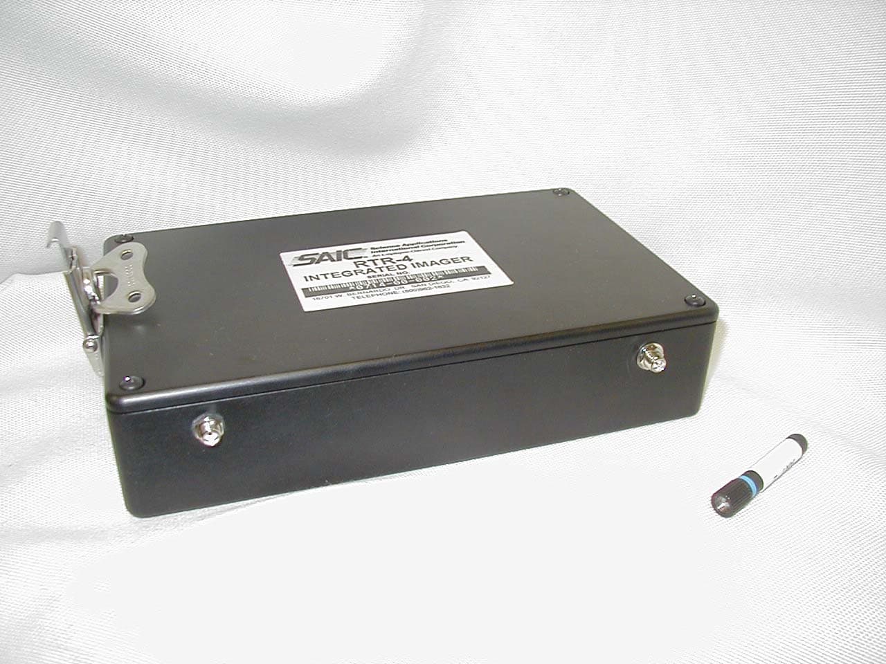
LPRRTR-4I
May 01, 2003Remote Control Transmitter
Equipment Class
DSC - Part 15 Security/Remote Control Transmitter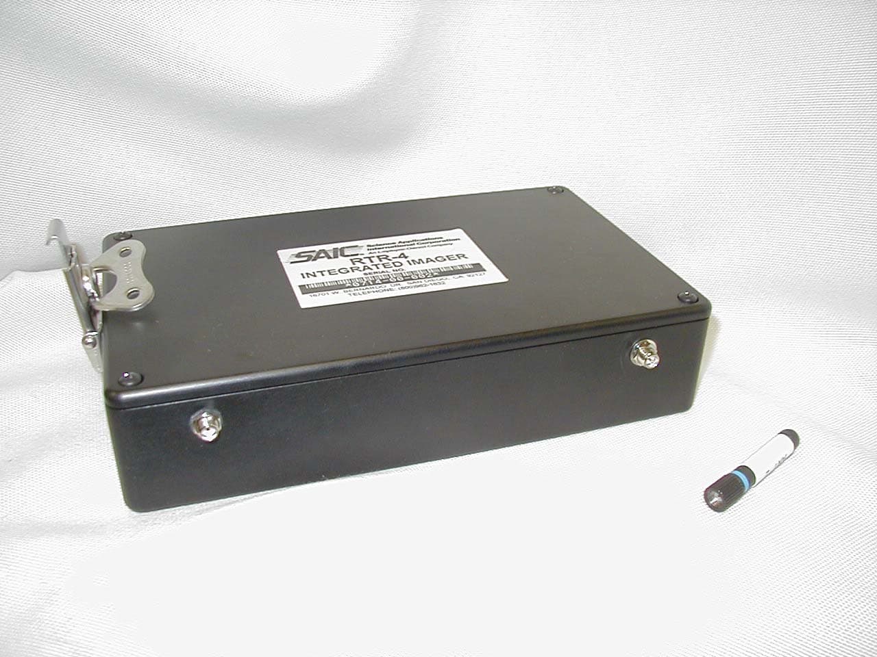
LPRRTR-RI
Apr 21, 2003Remote Control Transmitter
Equipment Class
DSC - Part 15 Security/Remote Control Transmitter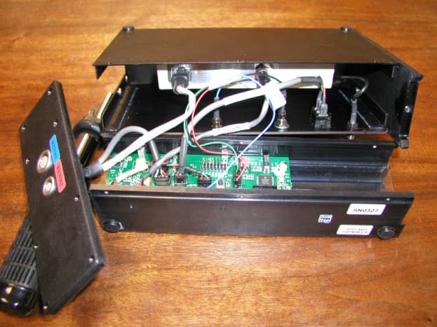
LPR418M1
Jul 11, 2002RTR-4 Wireless Option
Equipment Class
DSC - Part 15 Security/Remote Control Transmitter
LPRLPR902M-ICU-0
Mar 27, 2001AVL GPS
Equipment Class
TNB - Licensed Non-Broadcast Station Transmitter
LPRRTR-4418M
May 23, 2000Wireless Security Transmitter
Equipment Class
DSC - Part 15 Security/Remote Control Transmitter