M3N-32337800Receiver for Autmobile Remote Control System
Continental Automotive Systems, Inc.
Click to zoom
Application Details
- Equipment Class
- CYY - Communications Receiver used w/Pt 15 Transmitter
- Date of Grant
- Jan 08, 2013
- Application Purpose
- Original Equipment
- Date of Application
- Jan 08, 2013
- Equipment Note
- Receiver for Autmobile Remote Control System
- Frequency Range
- 433.90000000 - 433.90000000
- Country
- United States
Documents & Files
Document Text
Text extracted from the exhibit documents filed with the FCC. Open a document above to read the original.
Users Manual
The device under test is manufactured by the grantee (Continental Corporation) and sold as an OEM product. Per 47 CFR 2.909, 2.927, 2.931, 2.1033, 15.15(b) etc..., the grantee must ensure the end-user has all applicable / appropriate operating instructions. When end-user instructions are required, as in the case of this product, the grantee must notify the OEM to notify the enduser. Continental Corporation will supply this document to the reseller/distributor dictating what must be included in the end user’s manual for the commercial product. INF ORMATION TO BE INCLUDED IN THE END USER'S MANUAL The following information (in blue) must be included in the end product user’s manual to ensure continued FCC and Industry Canada regulatory compliance. The ID numbers must be included in the manual if the device label is not readily accessible to the end user. The compliance paragraphs below must be included in the user's manual. ****************************************************************************** FCC ID: M3N-32337800 CAN RSS-Gen/CNR-Gen This device complies with Part 15 of the FCC Rules and with Industry Canada license-exempt RSS standard(s). Operation is subject to the following two conditions: (1) This device may not cause harmful interference, and (2) This device must accept any interference received, including interference that may cause undesired operation. Le présent appareil est conforme aux CNR d'Industrie Canada applicables aux appareils radio exempts de licence. L'exploitation est autorisée aux deux conditions suivantes: (1) l'appareil ne doit pas produire de brouillage, et (2) l'utilisateur de l'appareil doit accepter tout brouillage radioélectrique subi, même si le brouillage est susceptible d'en compromettre le fonctionnement. Note: Changes or modifications not expressively approved by the party responsible for compliance could void the user's authority to operate the equipment. The term “IC:” before the radio certification number only signifies that Industry Canada technical specifications were met. ******************************************************************************
Cover Letter(s)
December 14, 2012 Federal Communications Commission Equipment Approval Services P.O. Box 358315 Pittsburgh, PA 15251-5315 Re: Certification for Continental Receiver Model/PN(s): A2C32337800 FCC ID: M3N-32337800 Please find enclosed application materials for certification of Continental Receiver. We tested it and found it to comply with FCC Part 15. If there are any questions regarding the application or testing performed, please contact me at the above address or call 734-483-4211, fax 734-647-2106, or e-mail [email protected]. Sincerely, Valdis V. Liepa Research Scientist
Cover Letter(s)
Re: Certification for Continental Receiver FCC ID: M3N-32337800 REQUEST FOR CONFIDENTIALITY Pursuant to FCC 47 CRF 0.457(d) and 0.459 and IC RSP-100, Section 10, Continental requests that a part of the subject application be held confidential. Continental has spent substantial effort in developing this product and it is one of the first of its kind in industry. Having the subject information easily available to "competition" would negate the advantage they have achieved by developing this product. Not protecting the details of the design will result in financial hardship. Type of Confidentiality Requested Exhibit Short Term Permanent (1) ID Label & Location Short Term Permanent (3) External Photos Short Term Permanent 1 (4) Block Diagram Short Term Permanent (5) Schematics Short Term Permanent (7) Test Setup Photos Short Term Permanent (8) User’s Manual Short Term Permanent (9) Internal Photos Short Term Permanent (10) Parts List & Placement Short Term Permanent (11) RF Exposure Short Term Permanent (12) Description of Operation 1. Block Diagram includes internal oscillator frequency information that the manufacturer considers to be proprietary. 2. . Permanent Confidentiality: Continental requests the exhibits listed above as permanently confidential be permanently withheld from public review. Short-Term Confidentiality (FCC Only): Continental requests the exhibits selected above as short term confidential be withheld from public view for a period of 45 days from the date of the Grant of Equipment Authorization and prior to marketing. If there are any questions regarding this request, please contact me at the above address or call 734-483-4211, fax 734-647-2106 or e-mail [email protected]. Sincerely, Valdis V. Liepa, Research Scientist University of Michigan
Operational Description
Functional description FCC ID:M3N-32337800 7 14.12.2012 CAN RSS-Gen/CNR-Gen 5. Functional Description The Global A RKE/TPM Receiver Module is a factory installed automotive module, powered from the automotive 12 Volt system. The module has an enable pin input that places the receiver in either the active or sleep mode. It receives the 433.92 MHz ASK / FSK 4.2 kb/s Manchester encoded transmitted signal from the driver carried Key Fob or the vehicle mounted tire pressure transmitters. This signal is received thru Antenna on board of the module. The signal is fed to 433.92 MHz SAW filter which then drives the low noise amplifier input of the high integration superheterodyne receiver integrated circuit. The output of the LNA drives the mixer, which also has the 423.22 MHz VCO/PLL derived local oscillator as an input. A 13.225625 MHz crystal oscillator is used as the frequency reference. The output of the mixer drives the 10.7 MHz ceramic filter which then drives the IF amplifier. The IF amp drives an ASK demodulator and FSK Demodulator. Each demodulator is followed by an active low pass filter and then the data slicer. The output of the FSK data slicer drives a digital switch which is control by the Microcontroller. The default FSK digital switch state is closed. Therefore the FSK data will drive the data buffer circuit and go to the DATA OUTPUT connector pin. The output of the ASK data slicer is fed to microcontroller which process the ASK data. If the wake up criteria of a RKE message is met then the microcontroller starts recording the message. The microcontroller send the message captured to the output buffer that is connected to the module data out connector pin while open the FSK digital switch.
Test Report
University of Michigan Radiation Laboratory FCC Part 15, IC RSS-210/Gen - Test Report No. 417124-650 Page 1 of 11 The University of Michigan Radiation Laboratory 3228 EECS Building Ann Arbor, MI 48109-2122 Tel: (734) 764-0500 Fax: (734) 647-2106 Measured Radio Frequency Emissions From Continental Automotive Systems US Inc. Receiver FCC ID: M3N-32337800 Test Report No. 417124-650 December 14, 2012 Copyright © 2012 For: Continental Automotive Systems US Inc. 2400 Executive Hills Drive Auburn Hills Michigan 48326-2980 Contact: David Reimus [email protected] Phone: (248) 764-6522 Fax: (248) 764-7281 Testing supervised by: Measurements made by: Valdis V. Liepa Report Approved by:__________________________ Valdis V. Liepa Test report written by: Valdis V. Liepa Research Scientist Summary Tests for compliance with FCC Regulations, CFR 47, Part 15 and with Industry Canada RSS-210/Gen, were performed on a Continental, FCC ID: M3N-32337800. This device under test (DUT) is subject to the rules and regulations as a Receiver. In testing completed on November 16, 2012, the DUT tested met the allowed specifications for radiated emissions by 13.0 dB. Conducted emissions are not subject to regulation as the DUT is powered by a 12 VDC vehicular power system. University of Michigan Radiation Laboratory FCC Part 15, IC RSS-210/Gen - Test Report No. 417124-650 Page 2 of 11 Table of Contents 1. Introduction ...................................................................................................................................... 3 2. Equipment Used ............................................................................................................................... 3 3. Device Under Test ........................................................................................................................... 4 3.1 Description & Block Diagram .............................................................................................. 4 3.2 Variants & Samples .............................................................................................................. 4 3.3 Modes of Operation .............................................................................................................. 4 3.4 Exemptions ........................................................................................................................... 4 3.5 EMC Relevant Modifications ............................................................................................... 4 4. Emissions Limits .............................................................................................................................. 5 4.1 Radiated Emissions Limits .................................................................................................... 5 4.2 Power Line Conducted Emissions Limits ............................................................................. 5 5. Measurement Procedures ................................................................................................................. 5 5.1 Semi-Anechoic Chamber Radiated Emissions ...................................................................... 5 5.2 Outdoor Radiated Emissions ................................................................................................. 5 5.3 Radiated Field Computations ................................................................................................ 6 5.4 Indoor Power Line Conducted Emissions ............................................................................. 6 5.5 Supply Voltage Variation ...................................................................................................... 6 6. Test Results : Radiated Emissions ................................................................................................... 7 6.1.1 Emission Spectrum ........................................................................................................... 7 6.1.2 Supply Voltage and Supply Voltage Variation ................................................................. 7 University of Michigan Radiation Laboratory FCC Part 15, IC RSS-210/Gen - Test Report No. 417124-650 Page 3 of 11 1. Introduction This Continental Receiver was tested for compliance with FCC Regulations, Part 15, adopted under Docket 87-389, April 18, 1989 as subsequently amended, and with Industry Canada RSS-210/Gen, Issue 8. Tests were performed at the University of Michigan Radiation Laboratory Willow Run Test Range following the procedures described in ANSI C63.4-2003 "Methods of Measurement of Radio-Noise Emissions from Low-Voltage Electrical and Electronic Equipment in the Range of 9 kHz to 40 GHz". The Site description and attenuation characteristics of the Open Site facility are on file with FCC Laboratory, Columbia, Maryland (FCC Reg. No: 91050) and with Industry Canada, Ottawa, ON (File Ref. No: IC 2057A-1). 2. Equipment Used The test equipment commonly used in our facility is listed in Table 2.1. Except where indicated as a pre- test, monitoring, or support device; all equipment listed below is a part of the University of Michigan Radiation Laboratory (UMRL) quality system. This quality system has been established to ensure all equipment has a clearly identifiable classification, calibration expiry date, and that all calibrations are traceable to national standards. Table 2.1 Test Equipment. Test Instrument Used Manufacturer/Model Q Number Spectrum Analyzer (9kHz-26GHz) Hewlett-Packard 8593E, SN: 3412A01131 HP8593E1 Spectrum Analyzer (9kHz-6.5GHz) Hewlett-Packard 8595E, SN: 3543A01546 JDB8595E Power Meter Hewlett-Packard, 432A HP432A1 Harmonic Mixer (26-40 GHz) Hewlett-Packard 11970A, SN: 3003A08327 HP11970A1 Harmonic Mixer (40-60 GHz) Hewlett-Packard 11970U, SN: 2332A00500 HP11970U1 Harmonic Mixer (75-110 GHz) Hewlett-Packard 11970W, SN: 2521A00179 HP11970W1 Harmonic Mixer (140-220 GHz) Pacific Millimeter Prod., GMA, SN: 26 PMPGMA1 S-Band Std…
Text truncated - open the document above for the full version.
Contact Information
Applicant
Mark Kenney
Technical Contact
University of Michigan/EECSValdis V. Liepa
[email protected]734-483-4211
1301 Beal Avenue · Ann Arbor, Michigan · United States
Test Firm
University of MichiganValdis Liepa
Technical Specifications
| # | Rule Parts | Frequency Range | Power Output |
|---|---|---|---|
| 1 | 15B | 433.9 MHz - 433.9 MHz | - |
Other Applications from Continental Automotive Systems, Inc.
M3NA2C786860
Dec 03, 2023LF Transmitter
Equipment Class
DCD - Part 15 Low Power Transmitter Below 1705 kHz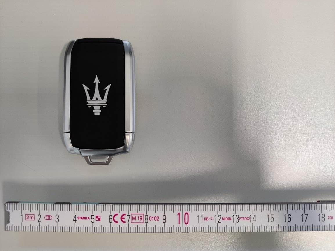
M3NRHT433
Jul 04, 2022KeyFob
Equipment Class
DSC - Part 15 Security/Remote Control Transmitter
M3NRCKF2B
Apr 25, 2021RCKF2B
Equipment Class
DSC - Part 15 Security/Remote Control Transmitter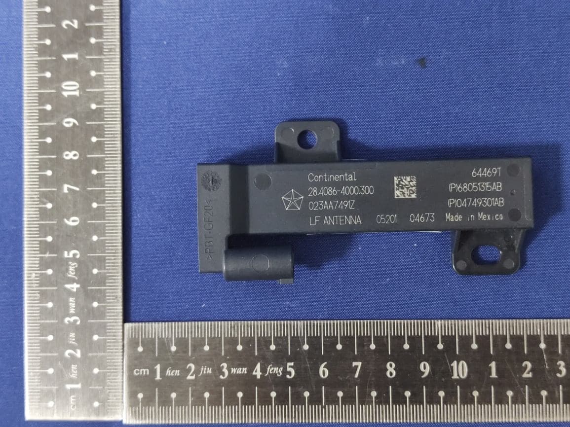
M3NWXRFHM1
Jan 28, 2021FCA WL/WS PASE System MY 2021
Equipment Class
DCD - Part 15 Low Power Transmitter Below 1705 kHz
M3NMAS433
Jan 20, 2021Car Key
Equipment Class
DSR - Part 15 Remote Control/Security Device Transceiver